A Nonlinear Control Strategy for Vienna Rectifier Under Unbalanced Input Voltage
2019-12-03RENXiaoyongCHENYuTONGDanZHANGZhiliangCHENQianhong
REN Xiaoyong,CHEN Yu,TONG Dan,ZHANG Zhiliang,CHEN Qianhong
Aero-Power Sci-Tech Center,College of Electronic Engineering,Nanjing University of Aeronautics and Astronautics,Nanjing 210016,P. R. China
(Received 15 May 2019;revised 10 July 2019;accepted 15 August 2019)
Abstract: The Vienna rectifier with unbalanced input voltage and load transient is analyzed. A nonlinear control strategy for Vienna rectifier under unbalanced input is proposed. From the view of positive and negative sequence components,the proposed nonlinear control strategy suppresses the twice frequency ripple and guarantees the dynamic response characteristic at the same time. Thanks to the proposed nonlinear control strategy,the DC bus capacitor can be reduced a lot since the voltage ripple and drop can be suppressed. A 10 kW Vienna rectifier is built to verify the proposed control strategy. After applying the proposed nonlinear control strategy,the voltage ripple is only 7 V and decreases over 75% over the traditional PI control when the unbalanced degree is 20%. The voltage drop can be reduced about 80% than former control strategy which is helpful to reduce the DC bus capacitor and achieve higher power density. The volume of the capacitor can be reduced by 83.3% with the new control method.
Key words: Vienna rectifier; radars; unbalanced input voltage; nonlinear control strategy; DC bus capacitance
0 Introduction
The increasing demand for high-power applications makes the application of three-phase PWM rectifiers more and more extensive. Among them,Vienna rectifier,as a three-level topology,has become the hotspot due to the advantages of low voltage stress,high power density,high efficiency and low total harmonic distortion(THD)[1]. Therefore,it is widely used in data center,telecom and aerospace power systems[2-4].
Since Vienna rectifier is a unidirectional converter,there could be twice power frequency ripple of the DC bus voltage when input voltage unbalance occurs in different phases[5]. In Vienna rectifier,the DC bus capacitor plays an important role since it can be increased purposely to suppress the twice frequency ripple. However,it should not be too large in order to achieve load transient performance[6-7].However,too many capacitor will increase the volume therefore sacrifice the power density. A traditional control strategy is to make the input phase current track the input voltage. Nevertheless,it cannot eliminate the input power ripple and output dc-link voltage ripple[8-9]. In Ref.[10],a current loop based on proportional resonant(PR) controller has been achieved according to the model under unbalanced input. It can achieve good input and output characteristics under unbalanced input,but it hurts the dynamic performance. Refs.[11-12]used passive control and sliding mode control respectively to optimize the dynamic performance of the nonlinear system,however,and these two methods are all based on balanced input,which is not suitable for unbalanced input voltage. Same thing happens in the load feed forward digital control scheme to optimize dynamic performance[13]. Ref.[14]used a digitized feed forward compensation to optimize the dynamic while this will improve the complexity of the control system and increase the requirement of the MCUs.
According to the model under the unbalanced input voltage,a nonlinear control strategy is proposed in this paper to obtain good performance for both steady and transient states. In the proposed nonlinear method,passive control for the current loop and sliding mode control for the voltage loop have been combined to guarantee a good dynamic response. With the new nonlinear control strategy,the DC bus capacitor can be reduced a lot since good steady state and dynamic performance can be obtained at the same time even under unbalanced input voltage.
This paper is organized as follows. In Section 1,based on the mathematical model for Vienna rectifier under unbalanced input,the problems under traditional PI controller have been analyzed. In Section 2,a novel nonlinear control strategy has been proposed to optimize the steady state characteristics under the unbalanced input voltage and dynamic response under the transient load. In Section 3,the experimental results are presented and discussed to verify the proposed nonlinear control strategy. Finally,the main points of this paper are summarized in Section 4.
1 Problems with Traditional Control Strategy for Vienna Rectifier
1. 1 Operation property of Vienna rectifier
Fig.1 shows the structure of the Vienna rectifier. Rland La,Lb,Lcare the equivalent resistance of input and boost inductors of each phase. Sa,Sband Scare the power switches of each phase. C1,C2and Roare the DC bus capacitors and the equivalent load of rectifier. ua,ub,uc,ia,ib,icare three-phase instantaneous input voltages and currents. ipk,iqkand ink(k=a,b,c)are currents flowing through the upper diode,power switches and lower diode,respectively.UC1,UC2and Udcare the rectified output voltages of upper capacitor,lower capacitor and total DC bus.ipand inare the currents through the positive and negative dc-bus. iMis the current flowing through the midpoint M.
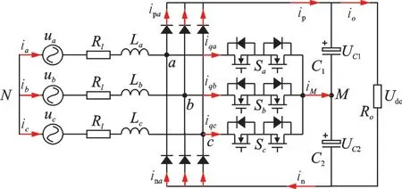
Fig.1 Topology of the Vienna rectifier
Under balanced condition,where ia+ib+ic=0 and ua+ub+uc=0. Sk(k=a,b,c)are the switching states of the bidirectional switch in Fig.1,then the switching functions can be defined as:Sk=1 means the switch is on;Sk=0 means the switch is off. If the neutral voltage is balanced(UC1=UC2=Udc/2),uican be given as

According to Kirchhoff’s voltage law,the mathematical model of Vienna rectifier under dq rotating reference frame can be derived as

where udq, idq, Sdqrepresent the components of three-phase instantaneous input voltage,input current and switching states under dq rotating reference frame.
1. 2 Problems with traditional control strategy under unbalanced voltage
Under balanced case,the typical control loop of the system under dq rotating reference frame is shown in Fig. 2,where PI controller is adopted in both the voltage and the current loop.
The output of the voltage loop is applied as the current reference of d-axis id*. The current reference of q-axis iq*is set zero. The output of the current loop is sent to the SVPWM module to generate the drive signal for each phase. The modulation strategy applied here is the equivalent SVPWM[15-16]. ωL is added as a coefficient to realize the power decoupling between d-axis and q-axis.
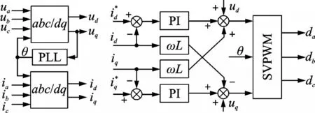
Fig.2 Traditional control strategy under dq rotating frame
There will be twice power frequency ripple of the output voltage when the rectifier works under unbalanced condition. In addition,the PI controllers used in control loop will inevitably cause ripple of the output voltage when three phase voltage are unbalanced or the load changes dynamically. Therefore,when the input or output conditions of the Vienna rectifier changes,its input and output characteristics will also be affected due to the poor anti-disturbance performance. In this case,in order to limit the output voltage ripple to a certain range,large capacitance is required and it will definitely influence the power density.
Fig. 3 shows d-axis current inner loop control block diagram of traditional double-loop control strategy of Vienna rectifier under dq rotating reference frame.

Fig.3 Control loop of the d-axis current
Corresponding transfer function of d-axis current inner loop can be achieved

where KdP+KdI/s is the transfer function of the PI controller, 1/(1+Tds) the delay time of current sample and DSP controller,and 1/(Ls+Rl) the transfer function of the main circuit. According to Routh Criterion,the control system is stable since all the the closed-loop feature roots are on the left side of the imaginary axis.
However, for unbalanced three-phase input voltage,there would be twice power frequency component in the instantaneous active power and reactive power,which means the input current idand iqhave twice frequency disturbance

where K1is a constant. Then the response of current error to the disturbance can be obtained

The denominator of Eq.(5)includes a pair of conjugate poles s1,2=±j2ω,which means this equation does not satisfy the final value theorem condition of Laplace transform[17]. In other words,the PI controller cannot realize tracking control without static error when variables contain twice frequency components.
Fig. 4 shows the steady state waveforms of a Vienna rectifier system with unbalanced input voltage.

Fig.4 Steady state waveforms of input current and output voltage under unbalanced input
The parameters involved in the simulation system are listed in Table 1.
As shown in Fig.4,there is apparent distortion of the current waveform. Additionally,the waveform of the DC bus voltage has twice power frequency ripple ΔUbus=25 V which will influence the steady state performance of the system. In brief,the traditional model and control method cannot elimi-nate the twice power frequency component,thus the DC bus voltage ripple become obvious. Also,it will hurt the THD of input current and power factor(PF)eventually.

Table 1 Parameters of simulation system
1. 3 Problems with traditional control strategy under transient load
If the line impedance is ignored under the condition of unity PF,which means iq=0 and Rl=0 in Eq.(2),then the d-axis current can be obtained

where io=Udc/Rois the output current of the rectifier.
Discrete and formulate Eq.(6)when the rectifier works with pure resistive load

The reference of the d-axis current component is

After performing discretization to Eq.(8),we can get

When Vienna rectifier works at a steady state,such simplification can be achieved

After combining Eqs.(7),(9),there is

where[idc(k+1)-idc(k)]/tsis the change rate of the d-axis current. Eq.(11)implies that the parameters of PI controller KdcPand KdcIin voltage loop are related to the output voltage and the change rate of the d-axis current. The parameters of main circuit such as L,C and the parameters of the controller such as KdcPand KdcIdoes not change when the rectifier is working. Accordingly, when the Vienna rectifier starts or has the transient load which means udchanges,the output voltage udcwill change too. Additionally,the PI controller has the lag part which will lead to a poor dynamic response when the load changes suddenly.
Fig.5 shows the waveforms of the output voltage when the load increases from 10% power to full power in Vienna rectifier whose parameters are listed in Table 1 under balanced condition. Since the control loop of output voltage uses traditional PI controller,the output voltage drops 55 V in Fig. 5 which does not satisfy the limit of the voltage drop.

Fig.5 Dynamic waveforms of output voltage under load transient
From the analysis above,in order to solve the problems under unbalanced input and load transient,we need to optimize the mathematical model and control strategy and replace PI controller with nonlinear controller.
2 Proposed Nonlinear Control Strategy for Vienna Rectifier
2. 1 Optimized mathematical model under unbalanced input voltage
Since the Vienna rectifier is a three-phase three-wire system,zero sequence component does not exist in the circuit. Therefore,the input voltage and current can be written into the sum of the positive and negative sequence component when three phase input is unbalanced

Then the instantaneous active power Pin(t)and reactive power Qin(t)can be achieved in Eqs.(13),(14). The instantaneous active power directly affects the output DC voltage.

where Pin_0and Qin_0are the DC components. The DC component of the reactive power Qin_0determines the PF value when the circuit operates. Pin(t)and Qin(t)also contain twice power frequency components including Pin_c2,Pin_s2,Qin_c2and Qin_s2. The twice power frequency ripple will be introduced into the DC voltage,when Pin_c2and Pin_s2are not zero.
Eq.(15)gives the detailed expression of Pin_0,Pin_c2, Pin_s2, Qin_0, Qin_c2and Qin_s2. Since Pin_c2=Qin_s2and Pin_s2= -Qin_c2,the ripple of the active power and inactive power can be eliminated at the same time. In order to realize the unity power factor and suppress the twice frequency ripple,the control targets can be set as:Qin_0=0,Pin_0= Poand Pin_s2=Pin_c2=0. Therefore,current reference can be written as Eq.(16)

Compared with the current reference id*acquired under the balanced input voltage in Section 1,the current reference id+*,id-*,iq+*and iq-*in Eq.(16)can guarantee none twice power frequency ripple at the DC bus even with unbalanced three-phase input. Combined with the traditional control loop in Fig. 2,extra three PI controller are required in id-*,iq+*and iq-*which will worsen the dynamic response a lot. Therefore,nonlinear control strategy is way more suitable here than the PI controller since it has better dynamic response than before.
2. 2 Proposed current loop based on passive controller
Compared with PI controller,passive controller is a nonlinear control strategy from the view of energy,which can improve the dynamic characteristics. Therefore,passive controller is a better choice than PI controller for the current loop[18-19].
From the analysis in Section 2.1,the mathematical model of Vienna rectifier under unbalanced input can be written as Eq.(17).
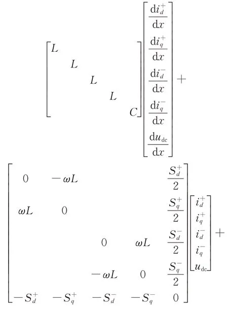
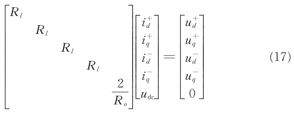
According to the Euler-Lagrange (EL) equation,the above equation can be written into EL model

where M is the energy storage term,J the connection term of internal interconnect structure,R the dissipative term and ε the input term of the system.From the point view of energy,the energy stored in C and L is always equal to the input energy of the system minus the energy dissipated in Rland Ro.
Based on the passive controller theory,for a with multiple-input multiple-output (MIMO) system

where x ∈Rnis the state variable,x ∈Rmthe input of the system,y the output of the system,f the partially continuous function on(x,u),and h the continuous function on(x,u). If there is a continuously differentiable semi-positive energy storage function H(x)and a positive definite function Q(x),for any T>0 the dissipative inequality satisfies Eq.(20),then the system is a strictly passive system.

where uTy is the energy supply rate. Assuming that the total energy function of the Vienna rectifier is

From Eqs.(18),(21),there is

Since J1+J2does not influence total energy of the system for it only reflects the structure,after integrating Eq.(22)on 0—T ,we can get

Therefore,the Vienna rectifier is a strictly passive system where passive control theory can be applied.
After substituting the error function xe= x - x*into Eq.(18),the dynamic characteristic of the error system can be obtained

According to the passive control theory,in order to make the error system dynamic characteristic converge to zero quickly,a dissipation term Raneed to be injected. The dissipation term after injection is Rd= R + Ra. Then,the new error system dynamic characteristic after injection can be obtained

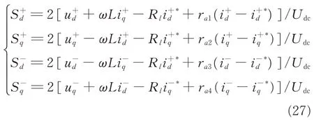
where Rais the injected dissipation term and R the initial damp term. The control law can be achieved in Eq.(26)since Mx˙e+ Jxe+ Rdxe= 0 need to be realized

After substituting Eq.(26)into Eq.(17),the switch function under passive controller can be achieved
2. 3 Proposed voltage loop based on sliding mode control
Compared with PI controller, sliding mode controller is a more suitable solution under unbalanced voltage input since the outer disturbance and change of the variables will not influence the operation of the system when it works on the sliding mode surface[20-21].

According to sliding mode variable structure control theory,the sliding mode surface is where m(m>0)is the sliding mode coefficient,xe5the input variable,x5the real value and x*5the reference. The larger m is,the less time the system takes to reach sliding mode. However,larger m will lead to a narrower area where the sliding mode exists. In the voltage control loop,the error between the DC bus voltage and the reference voltage xe5=x5-x*5=udc-u*dcis chosen as the input variable.
According to Eq.(17), when the rectifier works under unbalanced input voltage there is

Since the value of DC bus reference voltage will not change,du*dc/dt=0. Then Eq.(28)can be written as

After substituting Eq.(16)into Eq.(30),there is

When the system operates at a steady state,the reference value such as u*dccan be considered equal with udc. Then Eq.(16)can be written as

Therefore,the switch function Eq.(27)can be changed to
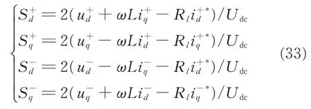
After substituting Eq.(33)into Eq.(29),the power reference under unbalanced input can be achieved

where the detailed expressions of K and K1are

In order to optimize the design of controller,assuming Rl=0,then Eq.(34)can be simplified as

Fig. 6 shows the control loop of the sliding mode controller. As can be seen in Fig.6,the variable Po*is applied as the output of the voltage loop which is sent to the current loop to acquire the reference of the current based on Eq.(16).

Fig.6 Control loop of the voltage loop
Fig. 7 shows the control block diagram of the proposed nonlinear control strategy. As can be seen in Fig. 7,the output of the rectifier ioand Udcare sent to the voltage loop where sliding mode control is applied. Then,the output of the voltage loop Po*is sent to the current reference diagram to get id+*,id-*,iq+*and iq-*. Finally,the current reference is sent to the current loop to get the duty of each phase.
The simulation has been built on the PLECS to compare two different control strategies under unbalanced input voltage. The parameters are the same with those in Table 1. When the load changes from to 10% load to full load,the waveforms are shown in Fig.8.
As can be seen in Fig.8(a),the voltage drop under traditional control strategy is 40 V and the time it takes to achieve steady state is around 30 ms.Additionally,the twice frequency voltage ripple is 10 V. However,with proposed nonlinear control strategy,the voltage drop and the steady time are only 5 V and 8 ms,respectively,in which the twice frequency voltage ripple is only 0.5 V. The simulation results show that the proposed nonlinear control strategy has a better performance for both dynamic and steady states than the initial one.

Fig.7 Block diagram of the proposed nonlinear control strategy

Fig.8 Simulation waveforms of DC link voltage under transient load
3 Experimental Verification
To verify the proposed nonlinear control strategy in Vienna rectifier under unbalanced input voltage,a prototype of 10 kW is built in Fig.9. The input phase-voltage of the convert is 220 V when three-phase voltage is balanced. The traditional control strategy is depicted in Fig.2,and the proposed nonlinear control is depicted in Fig.7. The constructed experiment is designed with the same parameters as those listed in Table 1. The controller of the prototype is implemented with TMS320F28075 DSP processor. The C28x floating point unit(FPU)fastRTS Library is applied here since it can realize the functions such as sinusoid and square root here. According to the application note of this library,the routines in this library can guarantee that the user can achieve execution speeds considerably faster than the past.

Fig.9 Experimental prototype
3. 1 Steady state waveforms under unbalanced voltage
Fig.10 compares the waveforms of DC bus voltage when three-phase input is unbalanced. The voltage of phase A is 110 V,the voltage of phase B is 110 V(+20%)and the voltage of phase C is 110 V(-20%). The blue waveform is the DC bus voltage. From Fig.10(a),the amplitude of twice power frequency voltage reaches 28 V under traditional control strategy. When the nonlinear control strategy is applied,the ripple can be reduced to 7 V that is only a quarter than the initial ripple. Accordingly,the voltage ripple can be reduced a lot under the proposed strategy.
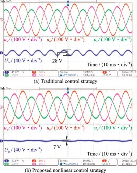
Fig.10 Waveforms of DC link voltage under unbalanced input
3. 2 Dynamic waveforms under load transient
Fig. 11 compares the waveforms of the input voltage,input current and DC bus voltage when the power jumps from 1 kW to 8 kW. As can be seen in Fig. 11(a),the drop of the DC bus voltage can reach 50 V under the traditional control strategy. Besides that,the time it takes to return the steady state is 200 ms. However,the voltage drop is only 12 V when nonlinear control strategy is implemented and the time can be reduced to 40 ms. The quality of the current waveform will not be influenced a lot under the proposed control strategy. Hence the new control strategy can increase dynamic characteristic and decrease the voltage drop strikingly.
3. 3 Capacitance decrease experiment

Fig.11 Experimental waveforms of DC link voltage under transient load
Since the proposed nonlinear control strategy can reduce the voltage drop when the load transient happens,the DC bus capacitor can be reduced to improve the power density of the rectifier. As can be seen in Fig.9,the initial capacitor of the prototype is 180 μF(×6). The waveforms of the DC bus voltage after reducing the capacitor to 180 μF(×3)are shown in Fig.12. As shown in Fig.12(a),the voltage drop under traditional control strategy can be 72 V that is unacceptable in the real operating condition. After applying the nonlinear control strategy,the voltage drop can be reduced to only 32 V less than the drop in Fig. 12(a) when the capacitor is 180 μF(×6). Accordingly,the capacitor can be reduced with purpose when the new control strategy is implemented for this can guarantee the same or even better dynamic characteristic than the initial control.
3. 4 The optimization of capacitance experiment
In order to achieve better performance of the steady state,the film capacitor and electrolytic capacitor are selected to absorb high frequency and low frequency current ripple,respectively. According to the rules of impedance matching[22],there is

Fig.12 Waveforms of DC link voltage under transient load after reducing capacitor
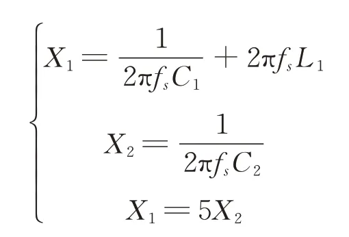
where C1is the electrolytic capacitor,and L1the inductor in series with C1and C2is the film capacitor.Since the value C1is much larger than C1,the inductor L1is required to realize that the low-frequency current ripple mainly flow through the electrolytic capacitor. The ratio between low-frequency and high-frequency is selected as 5∶1 here. The detailed parameters of the capacitor are shown in Table 2.

Table 2 Capacitor parameters
Fig.13 shows the waveforms of current flowing through the electrolytic capacitor ic1and the film capacitor ic2when the output power is 4 kW. After performing Fourier decomposition, we can get the spectrum of current flowing through capacitors. By comparing Fig. 13(a) and (b),we can find the low-frequency component of ic1is much larger than ic2which means the low-frequency ripple flows mainly through the electrolytic capacitor. On the contrary, the high-frequency current flows mainly through film capacitor since the high-frequency component of ic2is far more than ic1. It can also be found that current ripple at switching frequency of ic2is nearly five times that of ic1,which corresponds with the theoretical analysis. Therefore, the proposed CL-C connecting method can reduce the DC bus capacitance effectively and promise the same working performance.

Fig.13 Waveforms of DC link voltage and current under Fourier transform after reducing capacitor
3. 5 Comparison of steady state efficiency
The efficiency of the convert under two control strategies is shown in Fig.14.
As shown in Fig.14,the comparison of efficiency indicates that the nonlinear control strategy will influence the efficiency a little which is 98% when the load is 8 kW. Although the total efficiency decreases 0.5%,the Vienna rectifier can still have a high power frequency.
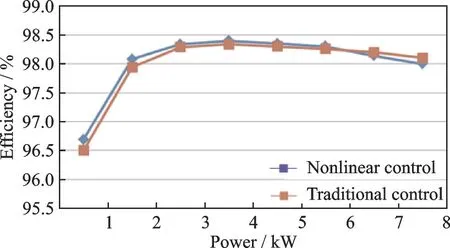
Fig.14 Efficiency of two control strategies under different load
4 Conclusions
A nonlinear control strategy in proposed in this paper to optimize the steady state performance and dynamic performance of the Vienna rectifier with unbalanced input voltage and load transient. From the view of positive and negative sequence component,the proposed nonlinear control strategy generated to suppress the twice frequency ripple caused by unbalanced input voltage. The current loop is based on the passive controller and the voltage loop is based on the sliding mode control which can guarantee the dynamic performance under load transient.
After applying the proposed nonlinear control strategy,the voltage ripple is only 7 V and decreases over 75% over the traditional PI control when the unbalance degree is 20%. The voltage drop can be reduced about 80% than former control strategy which is helpful to reduce the DC bus capacitor and achieve higher power density. Besides that,current ripple can be distributed effectively after applying the optimized CL-C connecting method as designed.The volume of the capacitor can be reduced by 50%with the new control method.
杂志排行
Transactions of Nanjing University of Aeronautics and Astronautics的其它文章
- Thrust Characteristics Analysis of Long Primary Double Sided Linear Induction Machine with Plate and Novel Shuttle Secondary Structure
- Interleaved-Connected Split Planar Resonant Inductor Design in 1 kV SiC LLC Converters
- A Modified Cohesive Zone Model for Simulation of Delamination Behavior in Laminated Composites
- Effect of Particle Size Distribution on Radiative Heat Transfer in High-Temperature Homogeneous Gas-Particle Mixtures
- Analysis and Calibration of Internal Flow Force of Ejector-Powered Engine Simulator System in Wind Tunnels
- Impinging Cooling with a Crescent Surface Inspired by Barchan Dunes in a Simplified Gas Turbine Transition Section
