Back Pressure Characteristics for Turbine Channel of External-Parallel TBCC Inlet
2019-12-03SUNBoXIANGCuilingZHUOChangfei
SUN Bo,XIANG Cuiling,ZHUO Changfei*
1. Department of Aerospace Engineering,Nanjing University of Science and Technology,Nanjing 210094,P.R. China;
2. Shanxi North Xing'an Chemical Indutry Co.,Ltd.,Taiyuan 030008,P.R. China.
(Received 28 May 2018;revised 24 April 2019;accepted 2 July 2019)
Abstract: For investigating the back pressure characteristics of turbine channel of an external -parallel turbine-based combined cycle(TBCC)inlet during the mode transition with the freestream air Mach number of 1.8,wind tunnel tests and numerical simulations are carried out. The results show that the critical back pressure of the turbine channel decreases linearly with the decrease of the open degree of splitter plate. The turbine channel has self-starting capacity when the open degree of the turbine channel is 100%. The total pressure recovery coefficient increases with the increase of back pressure when turbine channel is at supercritical and critical state. The mass capture ratio,total pressure recovery coefficient and outlet pressure ratio decrease obviously when turbine channel is at subcritical state.Results of the research would provide scheme reference and technology storage for TBCC propulsion evolution.
Key words: turbine-based combined cycle inlet; turbine channel; mode transition; back pressure; wind tunnel test
0 Introduction
Turbine-based combined cycle(TBCC)engine is a power device combining turbine engine and ramjet engine[1]. It combines the advantages of two engines in their respective flying conditions and satisfies the work requirements of hypersonic vehicle in the range of wide Mach number(0—5),which is an important research field in the hypersonic propulsion technology[2-4].
The mode transition of TBCC engine is the take-over process of turbine engine and ramjet engine. It mainly depends on the shunt effect of TBCC inlet to realize the take -over. The flow characteristics of both the turbine channel and the ramjet channel in the mode transition process determine whether the TBCC engine can safely achieve the smooth transition of the engine thrust. The research shows the overall performance of TBCC engine is very sensitive to the performance of inlet[5-7]. In the research field of TBCC propulsion system at home and abroad,the mode transition process has been studied specially. For example,in recent years,the US Aeronautics and Space Administration (NASA)has carried out the wind tunnel test on external-parallel TBCC inlet with cruise Mach number of 7.0,which has preliminarily obtained the operation characteristics of inlet during the mode transition process[8-9].
According to the relative position relationship between the turbine engine and the ramjet engine,TBCC inlet is mainly divided into series structure and parallel structure. Parallel structure can also be divided into external-parallel and internal-parallel[10].The turbine channel only share a part of the external compression section with the ramjet channel in the external-parallel TBCC inlet. Two channels are relatively independent, and the aerodynamic profile and regulating mechanism are easy to design,so the external-parallel TBCC inlet is a current research focus[11-12]. Many research institutes have carried out in-depth research and exploration for different schemes of external - parallel TBCC inlet. Wang et al[13-14]proposed an external-parallel variable geometry TBCC inlet with the operation range of Ma=0—4,and analyzed the flow characteristics of inlet during the mode transition using numerical simulation.
The turbine channel of TBCC inlet mainly works from the take - off to the end of mode transition. Its performance is not only related to the efficiency of the turbine engine,but also related to whether the inlet can match the turbine engine,and whether the mode transition can successfully complete[15]. The research results show that the back pressure at outlet of turbine channel has an important influence on mode transition[16]. Therefore,the study of its back pressure characteristic is of great significance.
In this paper,the wind tunnel test and numerical simulation are carried out on the mode transition process of turbine channel of external-parallel TBCC inlet,and the aerodynamic performance and flow characteristics of the turbine channel under different back pressure are obtained,based on the previous research result in our research team[17-18].
1 Inlet Model and Wind Tunnel Test Equipment
An scheme of external-parallel TBCC inlet is designed in this paper,as shown in Fig. 1. This scheme adopts the third level wedge of the external compression as the splitter plate,and takes the entry of the ramjet channel as the splitter hinge. The open and close of the turbine channel are controlled by rotating the splitter plate,and the ramjet channel is kept open,thus the mode transition of the external-parallel TBCC inlet is achieved.
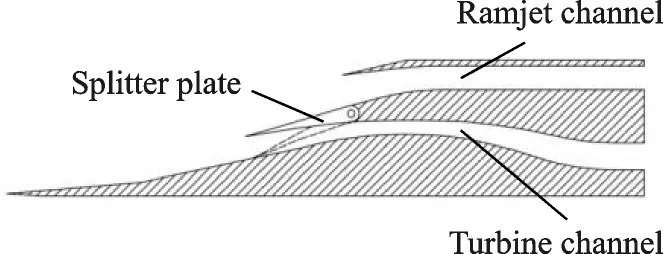
Fig.1 Schematic diagram of external-parallel TBCC inlet
According to the previous study in our research group,it shows that in the process of mode transition,the turbine channel of external-parallel TBCC inlet designed with this scheme is not affected by the ramjet channel,so the turbine channel can be separately taken out to study its back pressure characteristics. Accordingly,a wind tunnel test model for turbine channel is designed and manufactured. The three-dimensional structure diagram is shown in Fig.2(a),and the physical photo is shown in Fig.2(b).
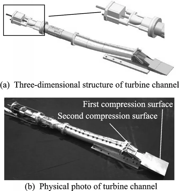
Fig.2 Test model of turbine channel
The test model is taken from an external-parallel TBCC inlet with design point of Ma=6.0,and Mach number of the mode transition is 1.8. When the entry of inlet is fully opened,the total contraction ratio is 2.71,and the internal contraction ratio is 1.09. The whole test model is composed of the first external compression surface,the second external compression surface,the internal compression section,divergent section and plug cone. The first external compression section adopts a simple wedge structure,and the compression angle is 4.8° taking into account that the loss of the leading edge shock is not too large. The divergent duct of the inlet is a rectangular-circular transition channel. Pitot pressure rake is placed at the outlet section of the divergent duct in order to measure the Pitot pressure at the outlet section. In order to simulate the back pressure produced by the combustion in the burner,the plug cone(Fig.2(a)) is used to impose the back pressure at the inlet outlet by adjusting the position of the plug cone. The movement of plug cone is controlled by a through DC stepping motor and driver.
The experiment is carried out in the 600 mm×600 mm high-speed wind tunnel(NH-1)at Nanjing University of Aeronautics and Astronautics. The wind tunnel is a transonic wind tunnel with high pressure blow down,including the high pressure gas source system,the stabilizer section,the nozzle,the test section,the electrical control system and the data acquisition system. It can realize the Mach number ranging from 0.3 to 2.5,and the operation time can be maintained for about 40 s in each test. The test conditions are shown in Table 1.

Table 1 Wind tunnel flow conditions
The experimental measurement system adopts the electronic scanning valve system of PSI company. There are five measuring modules in system,of which 53 pressure measuring taps are used in this work. There are 33 pressure measuring taps along the test model,including five taps in external compression section,seven taps in internal compression section,and 21 taps in the divergent section. The location of pressure measuring taps along test model is shown in Fig.3.

Fig.3 Layout of static pressure taps along test model
In order to monitor whether the turbine channel starts,the distribution of the measuring taps near the splitter plate is relatively dense. The Pitot pressure rake is arranged by the equal torus method.There are 25 measuring points of Pitot pressure rake,as shown in Fig. 4,including the measuring points located at the center of section. Two static pressure measuring points are arranged in the measuring section of Pitot pressure rake to measure the static pressure. In addition,the wave structure of the flow field is observed by using the schlieren device.

Fig.4 Layout of Pitot pressure rake
In order to simulate the mode transition process of turbine channel,that is,the process of the entrance section of test model transiting from full open to full close,the manual screw handle is designed to adjust the open degree of splitter plate(0°means the splitter plate is full open),and it is fixed on the side plate by screw. As shown in Fig.5,using the manual rotary handle,the splitter plate is rotated to 3°,6°,9° and 12°,respectively,to simulate the process of turbine channel transmitting from full open to full close. The downward rotation of the splitter plate of 3° corresponds to the 75.3% open degree of the turbine channel. The downward rotation of the splitter plate of 6° corresponds to the 50.1% open degree of the turbine channel. The downward rotation of the splitter plate of 9° corresponds to the 24.8% open degree of the turbine channel. The downward rotation of the splitter plate of 12° corresponds to the turbine channel of full close.
Under the condition of Mach number of 1.8,the wind tunnel test and numerical simulation are carried out on four states of the open degree of turbine channel,that are 100%,75.3%,50.1% and 24.8%. By adjusting the position of plug cone the back pressure changes. According to the schlieren video recording and the change of the measuring static pressure,it can determine whether the inlet reaches the critical state,and the performance of turbine channel under different back pressure are finally obtained.
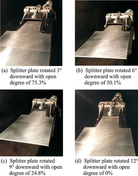
Fig.5 Different open degrees of splitter plate
2 Results and Discussion
2. 1 Back pressure characteristics of turbine channel with the open degree of 100%
The numerical results on symmetry plane of test model is shown in Fig.6. When the back pressure of the outlet is 3 times of the freestream static pressure,the inlet is at supercritical state (Fig. 6(a)). The main stream develops toward downstream along the upper wall,and the low-speed and low -energy region begins to develop in the front of the divergent duct and then expands gradually.When the back pressure of outlet increases to 4.3 times of the freestream static pressure,the inlet is at the critical state(Fig.6(b)). The normal shock wave locates at the third bleed holes,where is close to inlet throat,and the low-speed and low-energy region in the divergent duct develops toward downstream. When the back pressure further increases to 5 times of the freestream static pressure,the terminal normal shock wave is pushed out of the splitter plate and the inlet is at the unstarting state(Fig.6(c)).

Fig.6 Mach number contour under open degree of 100%
The back pressure is controlled by adjusting the position of the plug cone driven by a through DC stepping motor and driver. The flow parameters of inlet under the different position of plug cone(meaning the different back pressure) are collected with time,and each position of plug cone is numbered.The plug cone moves forward along the upwind flow direction from position #1 to position #5,indicating a gradual increase process of back pressure.The back pressure reaches the maximum when the plug cone locates in position #5. The plug cone moves backward along the downwind flow direction from position #5 to position #9,indicating a gradual decrease process of back pressure.
When the plug cone moves forward,the pressure distribution along the inlet is shown in Fig.7. In Fig.7,p denotes static pressure,peis the freestream static pressure,X is the distance from the inlet leading edge,and H is the entrance height of the inlet model. As the plug cone moves forward,the back pressure increases gradually. At the position #4 of plug cone(meaning the back pressure is 4.4 times the freestream static pressure),the inlet is almost at the critical state. The pressure signal is transmitted to the external compression surface when the plug cone locates at the position #5,indicating that the turbine channel is at unstarting state,causing a large number of overflow at the splitter plate. At this time the outlet pressure is lower than that of the position#4,which can also explain the turbine channel is in the unstarting state.

Fig.7 Experimental results of static pressure along the inlet when moving plug cone forward
When the plug cone moves backward,the pressure distribution along the inlet is shown in Fig. 8.With the plug cone moves backward,the back pressure decreases, and the turbine channel transits from the unstarting state at position #5 to the starting state at position #6. It also shows that the turbine channel has self - starting capacity when the open degree of the turbine channel is 100%.

Fig.8 Experimental results of static pressure along the inlet when moving plug cone backward
Fig. 9 shows the schlieren photographs of the starting state and unstarting state of inlet. A separated shock wave is produced in the front of the cowl lip at the unstarting state(Fig.9(b)).

Fig.9 Schilieren image of inlet state
Fig.10 shows the change of three performance parameters of mass capture ratio(the ratio of mass flow rate at the inlet exit to the theoretical maximum mass flow rate of the inlet),total pressure recovery coefficient(the ratio of the total pressure at the inlet exit to the freesteam total pressure)and outlet pressure ratio(the ratio of static pressure at the inlet exit to the freesteam static pressure)during the experiment by processing the data of Pitot pressure and static pressure of outlet section. In Fig.10,q(Ma)is calculated by using the exit Mach number and is relative to the back pressure produced by the plug cone. Mcrrepresents the mass capture ratio. Prrepresents the pressure ratio. PtRecrepresents the total pressure recovery coefficient. With the increase of back pressure,the inlet changes from supercritical state to critical state. It can be seen that under the starting state,the mass capture ratio of the inlet is less affected by the back pressure,but the total pressure recovery coefficient and outlet pressure ratio increase linearly with the increase of back pressure,and the total pressure recovery coefficient at the critical state reaches 0.79. It should be noted that the mass capture ratio is calculated by the capture area of the dual channel inlet model rather than the capture area of the single turbine channel. When the back pressure is further increased,the inlet is unstarted,and total pressure recovery coefficient and outlet pressure ratio decrease obviously. The total pressure recovery and pressure ratio obtained from the experiments and simulations respectively are very close,while the mass capture ratios obtained from these two methods have some difference which may be caused by the limited ability of simulations to model flow separation.

Fig.10 Numerical and experimental results of the inlet performance with the open degree of 100%
2. 2 Back pressure characteristics of turbine channel with the open degree of 75. 3%
The numerical results on symmetry plane of test model is shown in Fig. 11. It can be seen that the normal shock wave gradually moves from the front of divergent section to the cowl lip,and the inlet state is transited from supercritical to the subcritical state. When the back pressure of outlet increases to 3 times the freestream static pressure,the inlet is at the critical state,and the normal shock wave locates at the third bleed slot. When the back pressure further increases to 4 times the freestream static pressure,the terminal normal shock wave is pushed out of the cowl lip and the inlet is at the unstarting state.
In this section and subsequent section,only the effect of the plug cone moving forward on the performance of the turbine channel is studied.

Fig.11 Mach number contour under the open degree of 75.3%
When the plug cone moves forward,the pressure distribution along the inlet is shown in Fig.12.As the plug cone moves forward,the back pressure increases gradually. At the position #4 of plug cone(meaning the back pressure is 3.5 times the freestream static pressure),the inlet is almost at the critical state. Compared to the open degree of 100%,the critical back pressure decreases,that is,the withstanding back pressure capability of turbine channel decreases. The pressure signal has been transmitted to the splitter plate when the plug cone locates at the position #5,indicating that the turbine channel is at subcritical state at this time. When the plug cone locates at position #6 and position #7,the unstarting degree of the turbine channel is more serious,and lead to the serious spillage in front of the splitter plate.

Fig.12 Experimental results of static pressure along the inlet with the open degree of 75.3%
Fig.13 shows the change of three performance parameters of mass capture ratio,total pressure recovery coefficient and outlet pressure ratio during the experiment by processing the data of Pitot pressure and static pressure at the outlet section. With the increase of back pressure, the inlet changes from supercritical state to critical state. The total pressure recovery coefficient and outlet pressure ratio increase with the increase of back pressure,and the total pressure recovery coefficient at the critical state reaches 0.65. When the back pressure further increases,the inlet is in the unstarting state and the total pressure recovery coefficient and outlet pressure ratio decrease obviously.
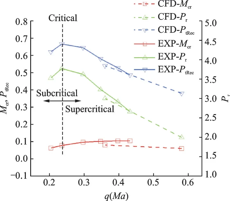
Fig.13 Numerical and experimental results of the inlet performance with the open degree of 75.3%
2. 3 Back pressure characteristics of turbine channel with the open degree of 50. 1%
The numerical results on symmetry plane of test model is shown in Fig. 14. Similar to the open degree of 75.3%,the normal shock wave gradually moves from the front of divergent section to the cowl lip,and the inlet state is transited from supercritical to the subcritical state. When the back pressure of outlet increases to 2.4 times the freestream static pressure,the inlet is in the critical state,and the normal shock wave locates at the third bleed slot. When the back pressure further increases to 3 times the freestream static pressure,the terminal normal shock wave is pushed out of the splitter plate and the inlet is at the unstarting state.
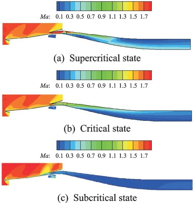
Fig.14 Mach number contour under the open degree of 50.1%

Fig.15 Experimental results of static pressure along the inlet with the open degree of 50.1%
When the plug cone moves forward,the pressure distribution along the inlet is shown in Fig.15.As the plug cone moves forward,the back pressure increases gradually. At the position #7 of plug cone(meaning the back pressure is 3.2 times the freestream static pressure),the inlet is almost at the critical state.
Fig.16 shows the change of three performance parameters of mass capture ratio,total pressure recovery coefficient and outlet pressure ratio during the experiment at the inlet outlet. With the increase of back pressure,the mass capture ratio basically remains unchanged,but the total pressure recovery coefficient and outlet pressure ratio decrease linearly with the increase of back pressure,and the total pressure recovery coefficient at the critical state reaches 0.56.

Fig.16 Numerical and experimental results of the inlet performance with the open degree of 50.1%
2. 4 Back pressure characteristics of turbine channel with the open degree of 24. 8%
The numerical results on symmetry plane of test model is shown in Fig.17. Similar to the previous ones,the inlet state is transited from supercritical to the subcritical state. When the back pressure of outlet increases to 1.7 times the freestream static pressure,the inlet is at the critical state,and the normal shock wave locates at the third bleed slot.When the back pressure further increases to 1.7 times the freestream static pressure,the terminal normal shock wave is pushed out of the cowl lip and the inlet is at the unstarting state.

Fig.17 Mach number contour under the open degree of 24.8%
When the plug cone moves forward,the pressure distribution along the inlet is shown in Fig.18.As the plug cone moves forward,the back pressure increases gradually. At the position #5 of plug cone(meaning the back pressure is 2.5 times the freestream static pressure),the inlet is almost at the critical state.

Fig.18 Experimental results of static pressure along the inlet with the open degree of 24.8%
Fig.19 shows the change of three performance parameters of mass capture ratio,total pressure recovery coefficient and outlet pressure ratio. With the increase of back pressure,the mass capture ratio basically remains unchanged,but the total pressure recovery coefficient and outlet pressure ratio increase linearly with the increase of back pressure(q(Ma)is decreasing),and the total pressure recovery coefficient at the critical state reaches 0.44.

Fig.19 Numerical and experimental results of the inlet performance with the open degree of 24.8%
3 Conclusions
In this paper,the numerical simulations and wind tunnel tests are carried out on the mode transition process of turbine channel of external - parallel TBCC inlet,and the aerodynamic performance and flow characteristics of the turbine channel under different back pressures are obtained. From the discussion in the above sections,the investigation can be summarized as follows:
(1)The turbine channel has self-starting capacity when the open degree of the turbine channel is 100%.
(2) With the decrease of open degree of turbine channel,the critical back pressure decreases,that is,the withstanding back pressure capability of turbine channel decreases.
(3)With the increase of back pressure,the total pressure recovery coefficient and outlet pressure ratio increase. But when the subcritical state occurs,the total pressure recovery coefficient and outlet pressure ratio decrease obviously with the increase of back pressure.
杂志排行
Transactions of Nanjing University of Aeronautics and Astronautics的其它文章
- Thrust Characteristics Analysis of Long Primary Double Sided Linear Induction Machine with Plate and Novel Shuttle Secondary Structure
- A Nonlinear Control Strategy for Vienna Rectifier Under Unbalanced Input Voltage
- Interleaved-Connected Split Planar Resonant Inductor Design in 1 kV SiC LLC Converters
- A Modified Cohesive Zone Model for Simulation of Delamination Behavior in Laminated Composites
- Effect of Particle Size Distribution on Radiative Heat Transfer in High-Temperature Homogeneous Gas-Particle Mixtures
- Analysis and Calibration of Internal Flow Force of Ejector-Powered Engine Simulator System in Wind Tunnels
