Effect of Impeller Extended Hub and Shroud on Centrifugal Compressor Stage Performance*
2019-11-14YanLiuPengfeiZhaoXiaoLiuYangWangHaiShi
Yan LiuPeng-fei ZhaoXiao LiuYang WangHai Shi
(1.School of Energy and Power Engineering,Dalian University of Technology,2.Qingdao Haixin Hitachi Air Conditioning Co.,Ltd,3.Shenyang Blower Works Group Corporation)
Abstract:CFD method was employed to analyze the effect of the wall extension of hub and shroud at the impeller outlet(rotating diffuser)in a centrifugal compressor model stage with a large mass flow coefficient.The effect of clearance leakage was considered.Results show that the extended hub and shroud increases the head coefficient and ploytropic efficiency for the centrifugal compressor stage,and the extension length is longer,the head coefficient and ploytropic efficiency is higher. When extension length is under 4.44%impeller outlet diameter(R2), the increase rate of head coefficient and polytropic efficiency is rapid. When the extension length is beyond 4.44% R2, the rate is slowed down. The uniformity at the diffuser inlet is to be improved, the total pressure loss of stationary parts decreases, and then the performance of stage is improved.The total pressure loss of stationary parts starts to reduce with the increase of mass flow coefficient when the extension length exceeds 5.56% R2 and mass flow coefficientis beyond the design value of 0.1957.
Keywords:Shrouded Centrifugal Compressor,Numerical Simulation,Clearance Leakage,Leakage Coefficient,Large Mass Flow Coefficient
Nomenclature
CpHeat capacity[J/kg/K]
CptTotal pressure loss coefficient
D2Impeller outlet diameter[m]
kAdiabatic exponent
nRotational speed[r/min]
PsPressure[Pa]
PtTotal pressure[Pa]
QmMass flow rate[kg/s]
RRadius[m]
HeRadial extension length of hub and shroud at impeller outlet
R2Impeller outlet radius[m]
RIdeal gas constant[J/kg/K]
Mu2Machine Mach Efficiency number
TtTotal temperature[K]
U2Circumferential velocity at impeller outlet[m/s]
ηPolytropic efficiency
ρin*Stagnation density[kg/m3]
τHead coefficient
ϕ1Flow coefficient
Subscripts
in Inlet
out Outlet
1 Introduction
Centrifugal compressors are widely used in many fields of industries including aviation,refrigeration,oil&gas and so on.Efficiency and operating range are the most important two performance characteristics for centrifugal compressors.
Energy losses occurred in a centrifugal compressor should be keep as low as possible to improve centrifugal compressor performance.These losses involves secondary flow loss,friction loss,leakage loss,separation loss,diffusion loss,mixing loss,incidence loss,etc.The flow at the outlet of a centrifugal impeller is non uniform both in the axi-al and circumferential directions.Consequently the mixing process of non-uniform flow causing a significant loss of total pressure and diffusion process resulting in a rise in static pressure will occur in the vaneless space downstream of the impeller.The more non-uniform the flow is,the larger the loss is.
One method to improve the non-uniformity of impeller outlet fluid flow is the use of a rotating vaneless diffuser.There are two types of rotating vaneless diffusers:free rotating vaneless diffuser and forced rotating vaneless diffuser.The former one is only a concept and rarely used due to requirement of driving device.The latter method is often used by extending the shroud and hub walls of a shrouded impeller.Therefore the forced rotating vaneless diffuser is integral with the impeller and rotates as the same speed as the impeller.Govardhan and Seralathan[1]numerically studied this types of rotating vaneless diffuser.Their results show that the performance of a compressor with extended walls is better than that of the baseline without extended walls.Again Seralathan and Chowdhury[2]numerically investigated the performance of a centrifugal compressor with the impeller blades cutback 5%while maintaining the original shroud and hub walls.Numerical results shows that the isoentropic efficiency declines when trimming impeller blades.Sapiro[3]experimentally studied the effect of extended shroud and hub walls on performance for a small mass flow coefficient compressor and a middle mass flow coefficient compressor.The performance of the compressor with extended shroud and hub walls is worse for the small flow coefficient compressor.The result is opposite for the middle mass flow coefficient compressor.The author implied that there will be a large improvement for a larger mass flow coefficient compressor with extended impeller shroud and hub walls.
The effect of impeller shroud and hub wall extension on performance for a large mass flow coefficient is studied by using the computational fluid dynamics(CFD)method.The seal leakage is considered in numerical simulations[4-5].The interaction of leakage vortex and the jet-wake structure is analyzed.
2 Configurations Investigated
A datum centrifugal compressor stage with design mass flow coefficient of 0.1957 and Mach number(Mu2)0.8 and its variants are studied.Fig.1(a)and(b)schematically show the datum impeller and the impeller with extended shroud and hub respectively.Different ratios ofHe/R2are considered.Table 1 summarizes the configurations investigated in this study.The labyrinth seal with five teeth for shroud(as shown in Fig.1)and ten teeth for hub(as shown in Fig.2)are employed.When extending the hub and shroud walls,the clearance(0.2mm)between seal tooth and case and the gap(2mm)between the impeller and the diffuser are kept the same for all cases.On account of the strength of the impeller,the maximum extension length is taken to be 10%R2(Case 5).It should be mentioned that stage performance measurements are only available for Case 0.
3 Numerical Methods
A single flow passage domain with periodic boundary conditions was employed to simulate the flow field of each configuration given in Table 1.The computational domain of Case 0 is shown in Fig.2.An unstructured tetrahedral grid generated by ICEM software was applied to the seal passage and the impeller passage.The tri-prism grid was used at the near wall regions with ten prismatic layers(as shown in Fig.2)for unstructured grids.A structure grid was employed for the diffuser,bend and return channel.Anish et al.[6]and Hazby et al.[7]employed the similar mesh strategy and numerical results are in reasonable agreement with experiment data.After a grid independence study,the unstructured mesh with about 3.4 millions of elements and structured mesh with about 1.5 million of nodes are used for all cases.The averageY+value is almost 2 for the first nodes away from walls in simulations.

Fig.1 Two types of impellers
Total pressure,total temperature and inlet flow angles were specified at the inlet.Different mass flow rates were imposed at the outlet.The periodic condition was imposed for the pitch-wise boundaries.The steady-state“Stage Inter-face”method was employed for interfaces between blade rows,which uses a mixing-plane interface approach.The mixing-plane interface was located atR/R2=1.156 for all cases.The Shear Stress Transport turbulence model of Menter[8]was employed due to its success in modeling flows in an adverse pressure gradient.Tan et al.[9],Jason et al.[10],and Mangani et al.[11]proved that this turbulence model is suitable for centrifugal compressor simulations.A“High Resolution”advection scheme(ANSYS Inc.,[12])was employed for all equations except for turbulence equations,which used a first order upwind scheme.

Tab.1 Configurations investigated

Tab.2 Primary geometric parameters for Cases 0-5
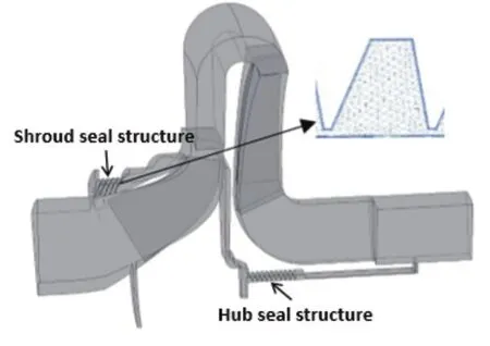
Fig.2 Computational domain and mesh of case 0
4 Results and Discussion
4.1 Verification of numerical results
Fig.3 compares the normalized predicted polytropic efficiency and normalized total pressure ratio(which are normalized by the experimental maximum value)with the experimental data for Case 0.Due to large pipeline net resistance,the maximum mass flow coefficient is limited and was not realized in the experiment.It can be seen that the predicted stage performance curves agree reasonably well with the experimental data.This demonstrates that simulation results are reliable and can be used for analysis.
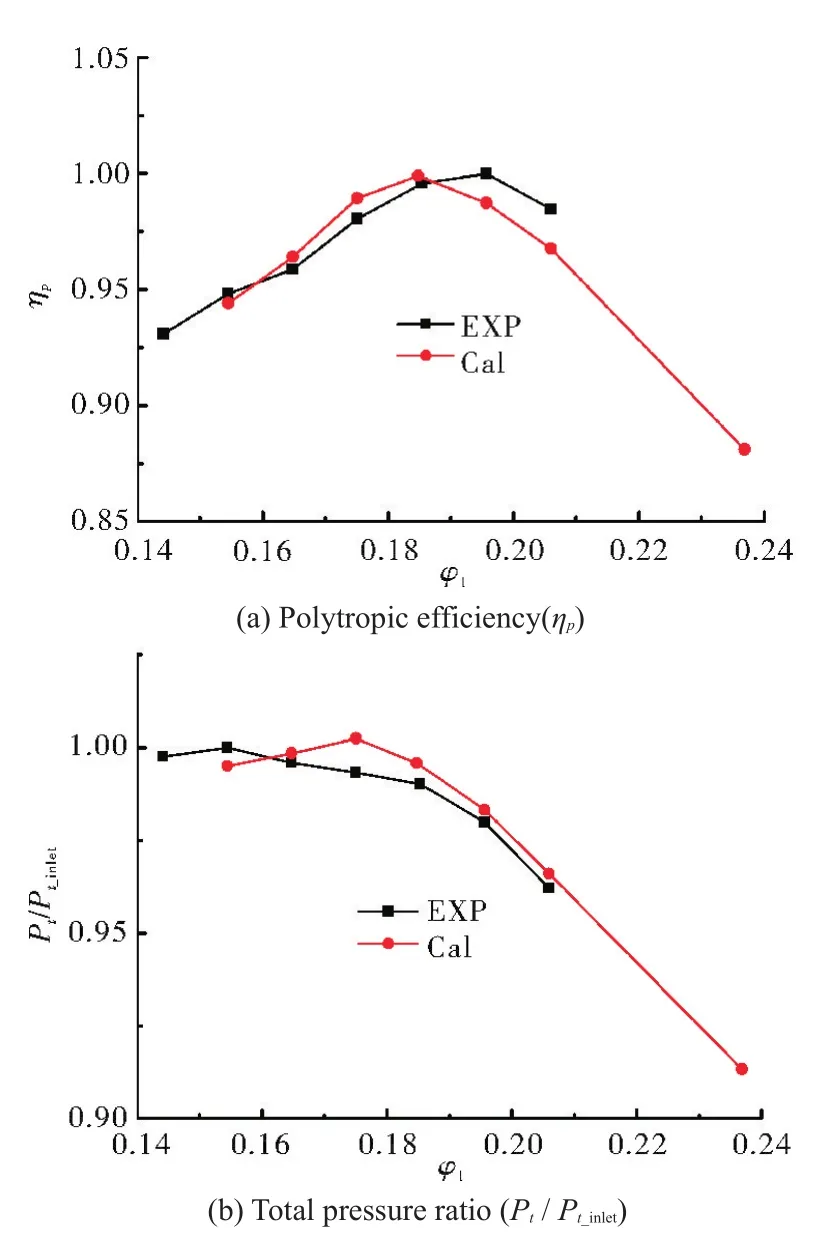
Fig.3 Comparison of polytropic efficiency and total pressure ratio
4.2 Effect of hub and shroud extensions on stage performance
Fig.4 contrasts the normalized polytropic efficiency for five extension cases with Case 0.It is can be seen that the polytropic efficiency increases with the increase in extension length,especially for off-design conditions.Also the range of high efficiency gets larger with the increase in extension length.Fig.5 shows changes of polytropic efficiency and head coefficient with shroud extension ratio(He/R2)for the six cases studied at the design condition ofϕ1=0.195 7.It can be found that the increase rate of polytropic efficiency and head coefficient is fasterwithHe/R2below 4.44%than that of beyond 4.44%.The reason why the head coefficient increases with the increase of shroud extension length is because the impeller area increases and the work increases.Reasons for the increase in polytropic efficiency will be explained in the next section.Saoiro[3]indicated when the extension length reaches beyond 25%R2,there is no improvement,even deterioation of the stage performance.In consideration of strength of the impeller,the maximum extension length i.e.10%R2is taken here.
4.3 Flow field analysis
The effects of extended hub and shroud walls on flow fields in the compressors is discussed.Table 3 shows leakage coefficients(βL,which is the leakage mass flow divided by the main mass flow)for the shroud and hub seals for the six cases at design condition(ϕ1=0.195 7).It can be found that the leakage coefficient increases with the increase of extension length.The longer the extension length is,the larger the pressure at the impeller outlet is,and hence the larger the leakage mass flow is.This is a negative influence on the leakage loss for extension of hub and shroud walls.In addition,it can be noted that the leakage coefficient of shroud seal side is larger than that of hub seal.Hence the leakage effect at hub seal side can be ignored.
In order to analyze the interaction mechanism between the leakage vortex and the jet-wake structure at the impeller outlet,vortex cores and 3D streamlines of relative velocity shown in Fig.6 at the design condition are used.It can be seen that there are four main vortices in Fig.6.They are trailing vortex at the impeller blade trailing edge,the wake vortex,leakage vortex near the blade suction side and the another leakage vortex near the blade pressure side.These vortices are denoted byA,B,C1andC2respectively.Ais caused by the thickness of the impeller blade trailing edge.Bis part of the jet-wake structure and is due to the secondary flow in the impeller passage.C1is leakage vortex near the blade suction side.The entrainment of vortex B makes some of the vortex in the leakage clearance leave the clearance,and flow into the diffuser passage.C2is the another leakage vortex near the blade pressure side,which is due to the interaction of the pressure side boundary layer and the shroud wall boundary layer at the corner.
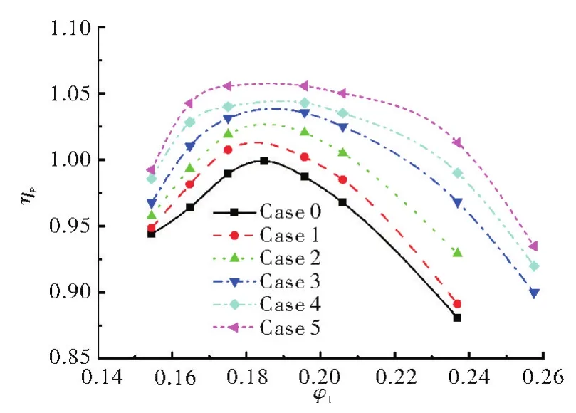
Fig.4 Contrast of polytropic efficiency of model stage for different cases

Fig.5 Polytropic efficiency and head coefficient changes with He/R2for 6 cases

Tab.3 Leakage coefficient for different cases
Fig.7 shows entropy contours at a plane near the shroud side for the six cases at design condition(ϕ1=0.195 7).With comparison to Fig.6,it can be found that the four high entropy value regions,which means the high loss regions,corresponding to the four vorticesA,B,C1andC2.As the extension length increases,C1andC2become weaker and small.When the extension length is beyond 10%R2,C1is not clear to be distinguished.
Fig.8 displays the static pressure ratio contour and surface streamline at a plane near the shroud side for the seven cases at design conditionϕ1=0.1957.The four vortexes are obvious for Case 0.Due to the effect of the viscous resistance at the diffuser wall and the expansion of radial channel,the fluid which flows out from the impeller passages is slowed down rapidly.The radial velocity is slower and the flow angle,which is the angle between the flow direction and the circumferential direction,is smaller.For Case 1,the strength ofC1andC2is smaller than that for Case 0,but the flow angle near the shroud side is still small.For Case 3,the flow angle increases,and this phenomenon is more obvious for Case 4 and Case 5.This is to say that the hub and shroud extensions of impeller outlet will reduce the strength ofC1andC2,and increase the flow angle near the shroud side.
Fig.9 shows the radial velocity contour at the cylindrical surface ofR/R2=1.006 for Case 0 and Case 5 forϕ1=0.1957.There are two low radial velocity zones,one is due to the wake of trailing edge and another is related to the wake region of the jet-wake construction.The radial velocity of wake structure for Case 5 is higher than that of Case 0.This means that the wall extension increases the radial velocity at the wake region,reduces the difference between jet and wake at impeller outlet and improves the flow uniformity.

Fig.6 Isosurfaces of swirling strength and streamlines of relative velocity at the impeller outlet for Case 0 at design condition

Fig.7 Contours of entropy at a plane near the shroud side

Fig.8 Pressure ratio contours and surface streamlines at a plane near the shroud side

Fig.9 Contours of radial velocity at the cylindrical surface of R/R2=1.006
Fig.10 and Fig.11 display mass-averaged flow angle and mass-averaged total pressure ratio distributions along the height of diffuser inlet atR/R2=1.158 forϕ1=0.195 7 respectively.Flow angle distributions are almost the same for Case 0,Case 1 and Case 2.When the extension length reaches 5.56%R2(Case 3),the flow angle near the shroud side becomes large and the flow uniformity improves.Because the extension wall does the work to the fluid,the total pressure is higher than that without extension wall as can be seen in Fig.11.With the increase of extension length,the value of total pressure increases too.
With regard to the performance of stationary parts,the inflow condition has a great influence on it.Because the inflow condition at the diffuser inlet is improved with the increase of extension length,the total pressure loss coefficient(Cpt)of stationary parts decreases.Fig.12 shows the total pressure loss coefficient distributions for six cases.Predicted results are in accordance with the theory analysis.TheCptof stationary parts decreases with the increase of extension length,especially for off-design conditions.Therefore the hub and shroud extensions at impeller outlet have benefits to decrease diffuser loss due to relatively good uniformity near the shroud side.Consequently the stage performance is improved as shown in Fig.4.
Fig.13 shows predicted mass-averaged flow angles along the width of channel atR/R2=1.158 for three cases and for different mass flow coefficients.It can be seen that generally flow angles increase from shroud to hub.Also with the increase inϕ1,flow angles at diffuser inlet increase especially near the shroud side.
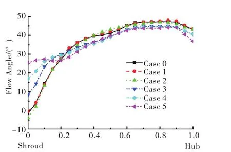
Fig.10 Distribution of mass-averaged flow angles along the width of the diffuser inlet

Fig.11 Distribution of total pressure ratio along the width of diffuser inlet
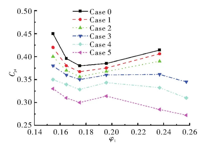
Fig.12 Total pressure loss coefficient of stationary parts

Fig.13 Distribution of mass-averaged flow angles at R/R2=1.158 for different ϕ1
5 Conclusions
The CFD method has been employed to analyze the flow field and performance of a centrifugal compressor stage with extended shroud and hub walls at the impeller outlet.Different extension lengths have been considered.Effects of extended walls on flow fields including leakage vortices and jet-wake structure and on the stationary component performance have been investigated.Main findings are given below:
1)Extension of hub and shroud walls not only increases head coefficient,ploytropic efficiency but also increases leakage flow.The increase rates of polytropic efficiency and head coefficient are faster when extension length is under 4.44%R2.The increase rates are slowing down when the length is beyond 4.44%R2.
2)The wall extension makes the leakage vortices decrease.When the extension length is beyond 4.44%R2,the flow angles at the shroud side of diffuser inlet begin to increase.
3)The extended walls improve the flow uniformity at the diffuser inlet.This helps reduce the total pressure loss of the stationary parts,and then improves the performance of the stage.
Acknowledgements
The authors gratefully acknowledge the support of Shenyang blower Works Group Corporation for providing the geometric parameters and experimental results of this centrifugal compressor stage.