Drilling study on lightweight structural Mg/SiC composite for defence applications
2019-10-31BlmurugnUthykumrThirumliKumrnSmyPilli
K.Blmurugn ,M.Uthykumr ,S.Thirumli Kumrn ,G.S.Smy ,U.T.S.Pilli
a Department of Mechanical Engineering,VFSTR(Deemed to be University),Guntur,522213,India
b Faculty of Mechanical Engineering,Kalasalingam University,Krishnankoil,626126,Tamil Nadu,India
c CSIR-NIIST,Material Science and Technology Division,Thiruvananthapuram,695019,India
Keywords:Magnesium SiC Drilling Thermal effect Chip morphology Tool wear
A B S T R A C T Heat energy generated during machining has been found to have a greater influence on determining the machinability of the materials.In this work,magnesium-based silicon carbide composite,which has been identified as a suitable lightweight application material,is prepared with the weight ratio of 90:10 by a stir casting process.Conventionally available HSS drill tools with different diameters of 4,6 and 8 mm are used to perform the drilling operations with governing parameters of spindle speed,feed rate and constant depth of cut.Thermal image camera of the FLIR E60 series is used to measure the temperature variation in the cutting zone at different operating conditions.The influences of machining temperature on chip morphology,tool wear and surface profile of the machined samples are investigated.Spindle speed has been found to have a significant effect on machining temperature.When spindle speed increases,the diameter of drill tool increases the tool wear and surface profile,respectively.Both abrasion and adhesive type of wears are observed in the drill tool.Further,change from abrasion to adhesive wear is noticed with the increase of the diameter of the drill tool.Surface plots are drawn with respect to the interaction of governing parameters along with the working temperatures obtained under different machining conditions.
1. Introduction
Metal matrix composites(MMC)had possessed excellent mechanical properties over a wide range of working conditions than available materials make it deemed fit for different engineering applications.Reinforced of particles on metal matrix have received considerable attention because of its various engineering properties like high strength to weight ratio,high toughness,high impact strength etc.Ye and Liu[1]have made a potential study on different fabrication techniques of magnesium matrix composites and concluded that matrix composition,dispersion,particle size predominantly determine the properties of the composite.Asadi et al.,[2]fabricated AZ91/SiC composite by a stir casting process and reported that the uniform dispersion of the particles on the matrix could not be achieved.Zhao-hui et al.[3]successfully fabricated magnesium composite with inform dispersion of nano-SiC particles using the ultrasonic method.
Matin et al.[4]have compared the microstructure of pure magnesium and SiC reinforced AZ80 nano-composites and identified that the reinforced SiC nanoparticles have the tendency to reduce the particle size of Mg.Nie et al.[5]have analyzed the microstructural characterization of a tensile test sample of Mg/SiC composite and it reveals that the initiation of microcracks is found within the SiC nanoparticle on the dense zones.According to Ajith Kumar et al.[6]and Gopalakannan&Senthilvelan[7]studies,it has been confirmed that SiC,as a reinforcement material tends to form excellent particle dispersion, fine grain size and an excellent interfacial bond with the base matrix.Poovazhagan et al.[8]have reported that the proper procedure of addition of Mg as alloying element helps in improving the wet ability and it reduces the surface tension. Poddar et al.[9]reported on the mechanical properties of Mg composite reinforced with 15 vol%SiC particulates with an average particle size of 15 μm and 150 μm and stated that the particle size of 15 μm gives an increase of yield strength by 10%.
Alphonse et al.[10]have delivered the importance of thermography studies,as it was a useful technique for identifying the defects that occur during machining and the defects can be eliminated well prior to the manufacturing of the product.Through Giasin and Soberanis[11]report,it can be confirmed that the noncontact thermo vision technique is a suitable alternative technique for temperature monitoring than the contact type. Hightemperature creep behavior of AZ91 reinforced SiC was analyzed by Viswanath et al.[12]using an infrared camera and confirmed that an improved creep resistance is obtained with the increase of reinforcement particles.Entire study on thermal behavior of materials using Infra red camera by thermography study was proven to be acceptable.Besides the surface topography,Myriounis et al.[13]had developed a new methodology to determine the fatigue property of a material through the thermographic image as by generated cutting temperature is converted to stress and through which the crack growth rates are measured.
Lazoglu et al.[14]have reported the thermal effect on the cutting tool and while machining Ti-6Al-4V,it has been concluded that the machining temperature significantly affects the productivity of property enhanced engineering materials.Geng et al.[15]have quoted that to obtain a minimum thermal distortion surface on the materials, the machining temperature has to be taken into consideration.Teixeira et al.[16]have performed a series of experiments to evaluate the machining temperature of different diameters of the drills and reported that the diameter of the drill tool has a significant effect on the cutting temperature.Harris et al.[17]have conducted a series of drilling experiments with two different tool bits on CFRP composite and it has been reported that the quality of the product varies with the tool bits.Rodriguez et al.[18]have found the abrasion,delamination and also the melt wear on magnesium based SiC composites reinforced with different propositions.According to Lee et al.[19]irrespective of spindle speed,drill bit diameter plays a significant role in the transfer of heat during the machining and hence there is a decrease in temperature is observed with the increase in drill bit diameter.Xu et al.[20]had been reported that above a certain spindle speed,the thrust force reaches a stable value and ceases to decrease with increasing spindle speeds,and also with the tool geometry.
By using ANOVA observation,Sheth and George[21]and Adalarasan et al.,[22]and Chang et al.,[23]have measured the machining performance of the materials using grey relational analysis and found the significant correlation between the experimental and the analytical results of each factors involved in machining operations.Magnesium and SiC are proven to be an excellent composite mixture because it has good dispersion property,wear resistance,increase in hardness,etc.,but the thermo mechanical behavior of the composite for the drilling operation using infra red camera has been not been reported.An attempt has been made to study the influence of temperature on the surface profile,tool wear and chip morphology with the varied parameters like spindle speed and feed at three different drilling tool.
2. Materials and methods
2.1. Preparation of composite
The commercially available magnesium powder of 1200 grams is melted in a steel crucible at 750°C under constant stirring condition.Preheated SiC particles of 120 grams are added slowly into the molten bath.At high stirring condition of 1200 rpm,it gets convenient for the hard SiC particles to disperse uniformly in the molten bath.The entire experiment is done in an argon atmosphere in order to avoid oxidation.The mixed molten bath is poured into the preheated mold made of mild steel.Finally,the removedsample is sandblasted and cut for the required shaped using abrasive waterjet machine.The samples are ground and then polished.

Table 1 The selected factors and various levels.
2.2. Experimental studies and procedures
Using Taguchi's L27 orthogonal array,the experiments are performed with various working conditions and they are shown in Table 1.
The dry drilling study has been conducted by using LMW JV 55 vertical drilling machine and it is shown in Fig.1.The drilling machine has a maximum spindle speed of 6000 rpm,the maximum feed rate of 10 m/min and spindle power of 7.5 kW.Taguchi's L27 orthogonal array has been employed to establish the level of experiments.Different cutting speeds of 2000,2500,3000 rpm,and feeds of 5,10,20 mm/s have been designated to carry out the experiments.HSS tool with different diameters of 4,6 and 8 mm is used to machine the workpiece.The temperature of the cutting zone is measured by using the FLIR E60 thermal image camera during drilling.The emissivity is taken with reference to the black body and it is found to be in the range of 0.07—0.13 for Mg and 0.83 to 0.96 for SiC at the room temperature of 32°C.The thermal conductivities of Mg and SiC are recorded to be 155 W/(K⋅m)and 120 W/(K⋅m),respectively.
3. Results and discussion
The drilling study is performed on Mg/SiC composite by using an L27 orthogonal array and it is shown in Table 2.The drilling temperature is taken as the individual response. The study of machining behavior in Mg/10%SiC metal matrix composite is imperative to optimize the cutting parameters.In addition to that,the effect of temperature increment contributes to the output responses likely chips formation,tool wear and surface morphology and they are studied and reported.
3.1. Machining temperature and effect on-chip interface
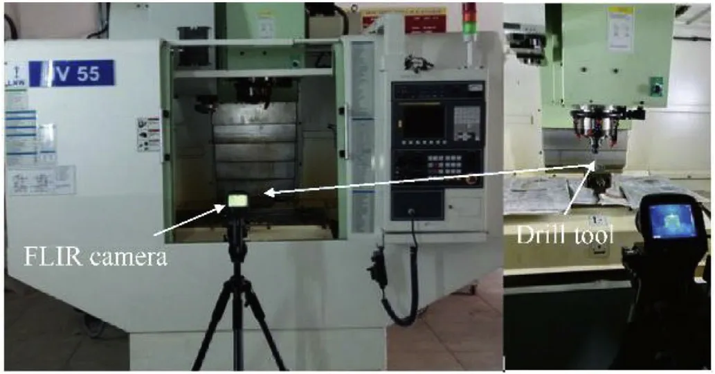
Fig.1.Experimental arrangements.
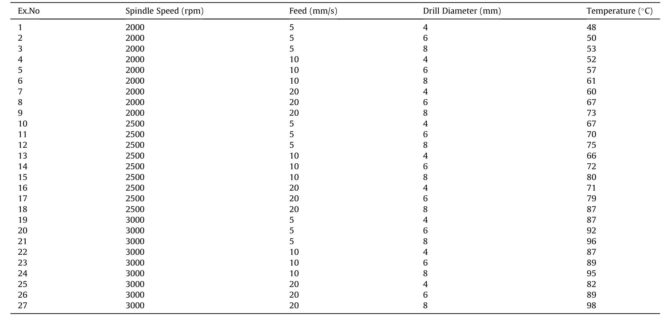
Table 2 Experimental observations on the drilling temperature.
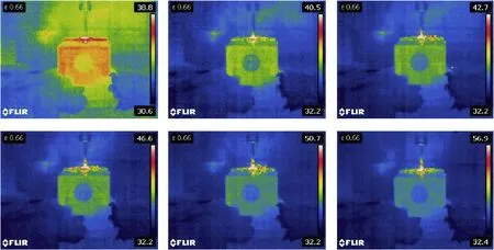
Fig.2.Shows the temperature rise during the drilling of Mg-10%SiC.
Fig.2 shows the rise in temperature along with the toolworkpiece interface zone during drilling of Mg/SiC composite.From the thermographic image,it is clearly noted that the temperature increases with increase in depth of the hole.Heat at the interference zone is distributed along the surface of the workpiece as well as the heat is rejected through chip extraction.At high spindle speed and feed rate,the temperature is very high,due to continuous interactions of tool and work.
Fig.3 depicts the chip formation behavior and thermographic image of various spindle speeds with a tool diameter of 8 mm at a constant feed rate of 5 mm/s.From Figure(3a),it is clearly noted that the increase in spindle speed accelerates chip extraction and also increases the chip curling length and this action is due to a rise in temperature.Initially,at the lower cutting speed of 2000 rpm,more numbers of fan-shaped chips are produced because of the discontinuous deformation which occurred on the newly removed surface.By this action,the chips are subsequently cracked,which affect the continuous flow of chip.It is evident from the thermographic images that there is a discontinuous flow of chip over the workpiece surface.
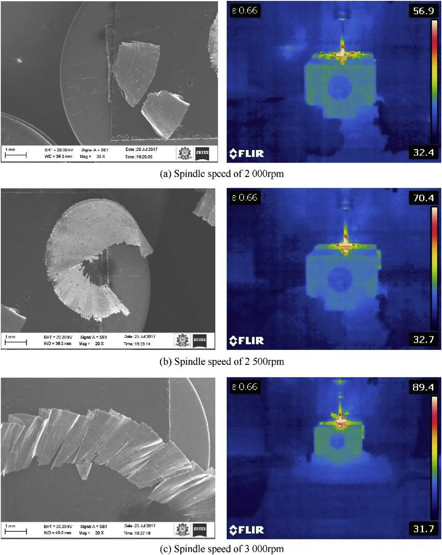
Fig.3.Shows the influence of spindle speed on chip formation at the tool diameter of 8 mm with a constant feed rate of 5 mm/s.
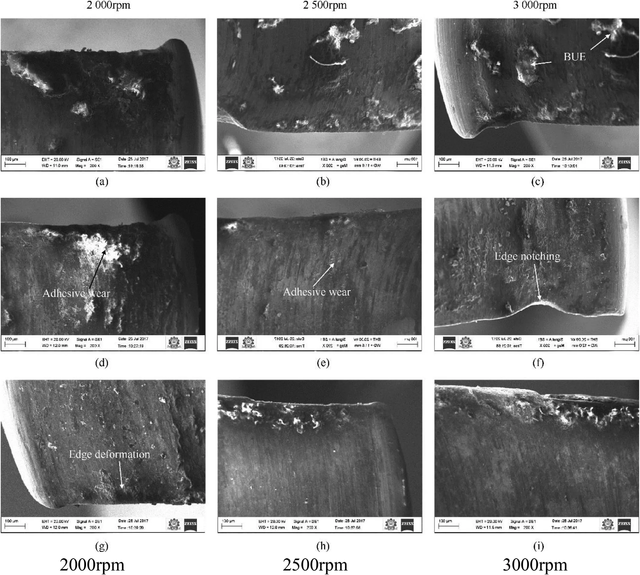
Fig.4.Shows the tool wear at different spindle speed with a feed rate of 20 mm/s.
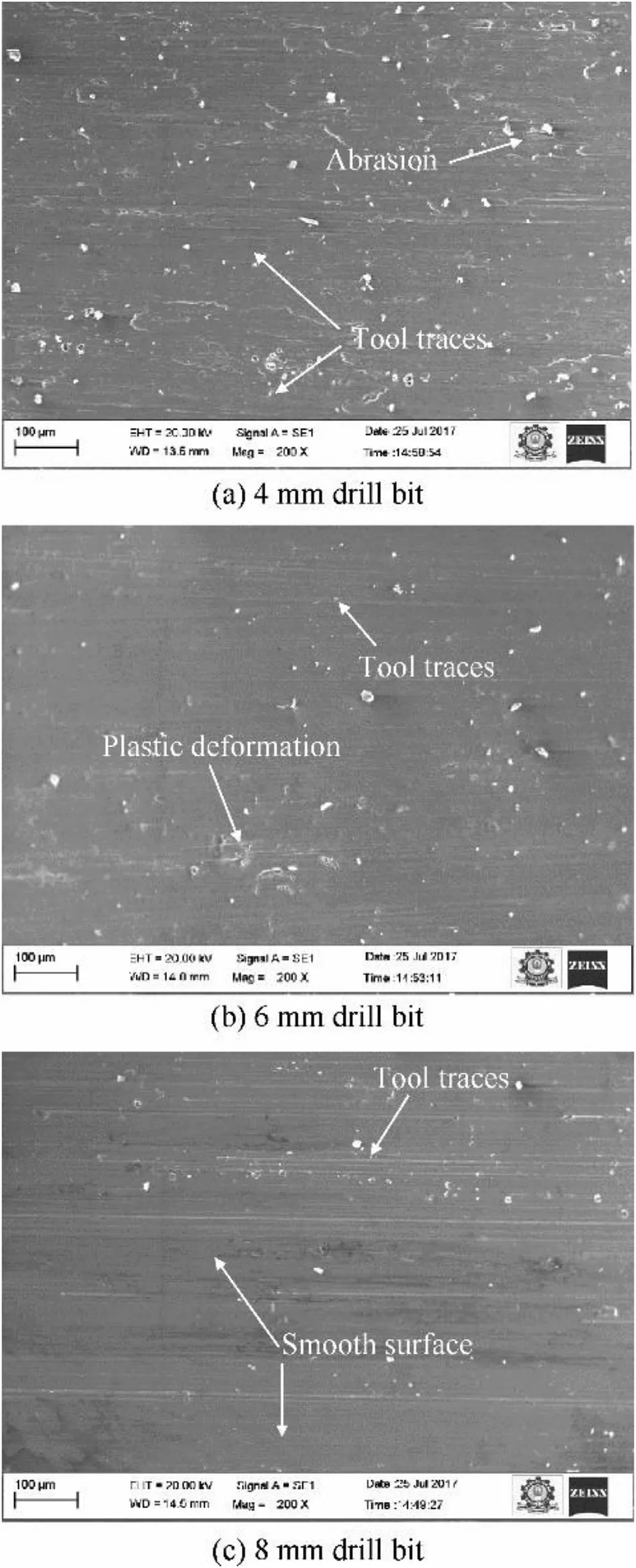
Fig.5.Shows effects of the different drill with spindle speed 3000 rpm and feed rate 20 mm/s.
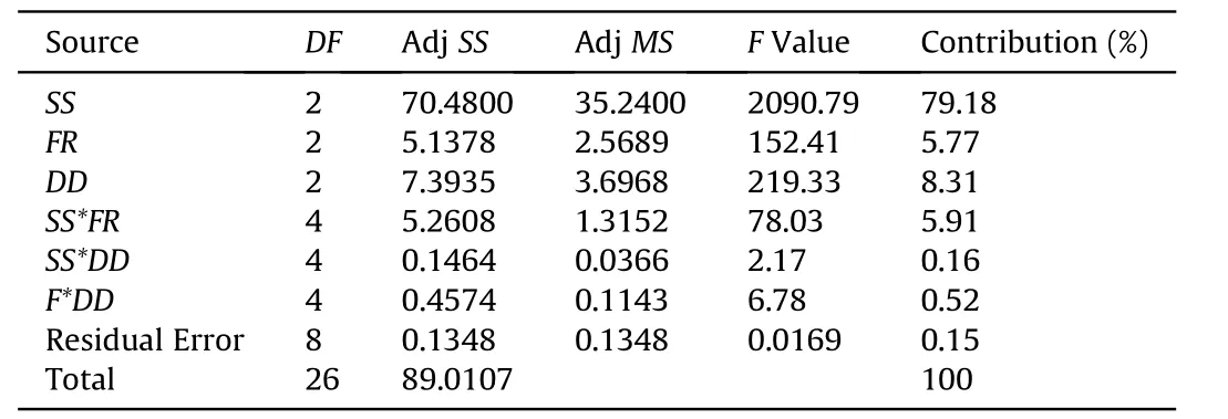
Table 3 Analysis of variance.
At 2500 rpm,the temperature rises relatively high enough to postpone the shear plane in the cutting zone and it causes curl in the chip flow to form conically shaped chips.The thermographic image in Figure(3b)also reveals the rise in temperature and it reduces the formation of fan-shaped chips.With the increase in spindle speed of 3000 rpm,the chip shape is transformed from short conical to continuous folded ribbon shape and it is shown in Figure(3c).The temperature of the cutting zone increases with respect to an increase in the feed rate of the drill.Also,a significant increase in chip thickness affects the chip continuous flow and causes chip clogging.
For the case of 4 mm and 6 mm diameter drills,short crumbled discontinuous fan-shaped chips are noted.Further,it is noticed that on increasing the spindle speed,the chips formed are crumbled discontinuous fan-shaped with a slight increase in curl length.However,the discontinuous chip formation reveals the temperature nature as a minimum at cutting zone and it helps in enhancing the thermal evacuation at the cutting zone while performing the drilling operation on this composite.
3.2. Machining temperature on tool wear
Fig.4 shows the different tool wears on the flank face and cutting edge at various spindle speeds with respect to temperature rise,during the drilling of Mg/SiC composite at 20 mm/s.For 4 mm diameter drill at a low spindle speed,adhesive wears are found on the flank and cutting edge which causes the Built-Up Edge(BUE)formation on the tool and newly machined work surface.The increase in spindle speed increases adhesive wear and BUE formation on the tool surface.This is due to the acceleration of the chemical affinity of the composite with the tool and it results in a rise in temperature of cutting zone as shown in Fig.4(a—c).
For the case of 6 mm diameter drill,at lower spindle speed,abrasion wear is noted highly rather than adhesive wear and it is evident from SEM image shown in Fig.4(d—f).The abrasion wear is formed at a spindle speed of 2500 rpm and it is due to the hard reinforcement of SiC particle and acceleration of chip flow.This action continuously tears the tool and causes abrasion wear.At high spindle speed,increase in abrasion wear leads to the formation of an edge notching as shown in Fig.4(f).
For 8 mm drill,two different types of wear mechanisms are noted and they are shown in Fig.4(g—i).At a low spindle speed of 2000 rpm,abrasion wear and edge deformation occur,which lead to the increment of flank wear on drill tool.The abrasion wear is dominated by adhesion wear and this is due to the increase of contact area of cutting edge compared to 4 mm and 6 mm diameter drills.At a high spindle speed of 3000 rpm,the combination of abrasion and adhesive wear is noted on the cutting edge of the drill.At first,abrasion wear occurs at the cutting edge and its propagation is restricted by adhesive wear.This is due to the rise in temperature and that causes an increase in chemical affinity and BUE formation to protect the tool from abrasion wear.From this study,it is proposed that for this composite,low spindle speed offers less tool wear irrespective of drill tool diameters.
3.3. Machining temperature on the surface profile
Fig.5 shows the SEM image of the surface profile on the machined surface for different drill diameters at a high spindle speed of 3000 rpm and FR of 10 mm/s.Fig.5(a)shows the SEM image of 4 mm diameter machined surface.It is found that there are more numbers of BUE formation and abrasion tool wear traces on the surface and hence,it causes poor surface finish.These abrasion wear traces and plastic deformation are found to be minimum in 6 mm diameter drill and is shown in Fig.5(b).This effect happens due to the domination of BUE on the tool.The increase in drill diameter improves the surface quality of the composite and it is shown in Fig.5(c).This is mainly due to the increase in contact surface area between tool and work and that significantly reduces drill force concentration over the surfaces.
3.4. Machining performances on the composite
Taguchi's L27 orthogonal array is used to evaluate the machining performance and the dominating machining factors are identified through the ANOVA table.They are shown in Table 3.The Spindle Speed(SS)itself contributes nearly 79%,whereas Feed Rate(FR)and the diameter of the Diameter of the Drill tool(DD)have the contributions of nearly 5% and 8%, respectively. However, at the interaction part,SS vs FR has a significant effect on determining the working temperature of nearly 6%.R2and Adj R2are found to be greater than 95%and it is found to be in the acceptable level.Through the F-Table observations,it can be confirmed that SS,FR and DD and interaction of SS vs FR have significant effects on the machining temperature.
3.5. The surface plot of the temperature distribution
The inference effect of each independent factor on the temperature is shown in Fig.6.The effects of DD and spindle speed on Temperature(T)are shown in Fig.6(a)and from the surface plot,it is identified that the rate of increase in T is superior in SS to DD.The interaction effects of F and DD are shown in Fig.6(b).The difference in the rise of temperature with changes in the level of independent parameters has a least significant effect.The surface plotted between SS and F with respect to T is shown in Fig.6(c).A sudden rise in working temperature is observed with the increase in levels of independent factors.This could be understood from the ANOVA table.The increase in the contact area makes the temperature increase.SN plot is shown in Fig.6(d)could confirm that the effects of each independent factor over the output responses are in the order of SS,followed by DD and FR.
4. Conclusion
Lightweight application material,Mg/SiC composite has been successfully prepared using stir casting process.Using an L27 orthogonal array,the composite is drilled with varied parameters.The machining performance of the composite is studied using SS,FR,and DD on drilling temperature.The effect of cutting temperature is studied using the thermography image,chip formation,wear on drill tool and the surface profile of the drilled composite.The study reveals the following:
·Short crumbled discontinuous chips are extracted during machining of the composite with 4 mm and 6 mm diameter drills whereas curled chips,fan-shaped chips,and continuous folded ribbon-shaped chips are extracted from 8 mm diameter drill tool.
·Discontinuous chips are found to extract heat from the machining zone than the continuous chips.However,the increase in temperature increases the thickness of the chips and that leads to chip clogging.
·The chemical affinity between the tool and the workpiece causes adhesive wear and BUE.For 4 mm and 6 mm drill tools,due to low surface contact,adhesive wear is found to be the dominated over other wears whereas,in 8 mm drill tool,abrasion wear has been recorded to be the superior to adhesive wear.Also,the hard reinforcement of SiC particle causes abrasion wear at low temperature.
·An improved surface profile is obtained with larger the diameter of the drill tool.
·ANOVA observations confirm that SS has a high influence on working temperature and also the interaction between the SS and the FR has a significant effect on the output response.
·Through the surface plot,the interaction effect of each independent parameter on the rise in temperature is clearly demonstrated.
杂志排行
Defence Technology的其它文章
- Modeling on the shock wave in spheres hypervelocity impact on flat plates
- Insensitive high explosives:IV.Nitroguanidine—Initiation&detonation
- Effect of energy content of the nitraminic plastic bonded explosives on their performance and sensitivity characteristics
- Effect of wave shaper on reactive materials jet formation and its penetration performance
- A comparative study for the impact performance of shaped charge JET on UHPC targets
- The role of crystal lattice free volume in nitramine detonation
