Four-axis trochoidal toolpath planning for rough milling of aero-engine blisks
2019-09-28MingLUOCeHAHHfizHAFEEZ
Ming LUO, Ce HAH, Hfiz M. HAFEEZ
a Key Laboratory of Contemporary Design and Integrated Manufacturing Technology (Northwestern Polytechnical University), Ministry of Education, Xi’an 710072, China
b Beijing Jingdiao Group Co., Ltd., Beijing 102308, China
KEYWORDS
Abstract The Blade Integrated Disk (Blisk) is one of the key components in the aero-engine, it is generally manufactured by the multi-axis milling and almost 90% raw materials are removed. To avoid the full immersion of a cutter in the rough machining of a blisk channel, the trochoidal milling is a promising strategy since it can keep a small immersion angle in the rough milling process while maintaining the high machining efficiency. However, while toolpaths are being planned for the trochoidal milling process,the conventional methods are mainly for the planar machining area with fixed tool orientations, which cannot be used for complex channels where the multi-axis machining should be employed. To this end, this paper presents a four-axis trochoidal toolpath planning method with a ball-end cutter, and thus the blisk channel can be machined efficiently.For this to happen, the trochoidal paths are planned in the parametric domain and then mapped into the physical domain,with tool orientations controlled by the quaternion interpolation method to have smooth tool movement along the toolpaths.Both geometric simulation and physical milling experiments of the proposed method have convincingly demonstrated the validation of the proposed method.
1. Introduction
Blisk is an integral structure that is widely used in the aeroengine to reduce weight and to improve working efficiency.A blisk is usually made of hard-to-cut materials, such as Nibased super alloy and Titanium alloy. Due to their high heat resistance and dense structure, the cutting force and temperature during the cutting process are very high, which result in fast tool wear and low machining efficiency.1,2Besides,a blisk is usually machined from a cylindrical-like blank part, more than 90% raw material of the blank part has to be removed to form the final part,3and it usually costs days or even weeks to machine one blisk.Therefore,machining efficiency improvement for blisk is a focus issue in the aero-engine manufacturing industry.
There are mainly three machining processes for rough milling of blisk,the point milling,end/flank milling and plunge milling.As for the point milling or end milling,a ball-end cutter4or flat-end cutter is used to remove the raw material,and a slot milling is usually needed for each layer. Typically, specially designed cutters such as barrel cutter can be used for high-efficiency milling of a blisk or an impeller.5,6In regard to plunge milling, Ren et al.7developed a four-axis plunge milling method for the blisk manufacturing, and their results show that the cutting force reduced about 60% compared to the end milling process. Besides, the machining efficiency is about two times higher than the end milling. Later, Liang et al.8improved the plunge milling process to get a balanced tool load and higher machining efficiency by optimizing the tool orientation and cutter location.To further control the cutting force and tool life, Sun et al.9developed a plunge milling toolpath generation method,and the radial depth of cut is controlled by the offset contour generated by the medial axis transform.Furthermore,Han et al.10presented a tool diameter optimization method for the plunge milling, and the largest allowed cutter is used for milling the impeller channel to improve the machining efficiency. In general, the plunge milling provides an efficient machining method for roughing an open blisk,and it is now widely used in the industry.However, the plunge milling process also has some disadvantages:expensive plunge cutters are usually needed for milling hardto-cut materials, and the power of the machine tool has to be high enough.
In regard to milling of hard-to-cut materials, such as Nibased super alloy or Titanium alloy, machining parameters are usually optimized to reduce the cutting force and to extend the tool life.11The main concern in milling of hard-to-cut materials is to control the cutting force and tool wear.12Fast tool wear is mainly caused by the strong thermodynamic coupling effect in the milling process, and the task of machining parameter optimization is to control this effect. Although the tool wear can be monitored by on-line methods,13approaches to control the wear rate are still a main concern. Generally,optimized machining parameters are incorporated into the toolpath planning stage to take effect. Trochoidal toolpath is a commonly used strategy in the commercial software and in high-speed milling process while the thermodynamic coupling effect is taken into consideration, and the trochoidal milling method becomes a promising approach in milling of the hard-to-cut materials.14Otkur and Lazoglu15modeled the trochoidal milling process and introduced the double trochoidal milling mechanism.Sui et al.16applied the clothoid curve transition in the corner-looping milling process to control the cutting force and dynamic characteristics, and their results show that the machining quality of the surface can be improved.Rauch et al.17compared the trochoidal and plunging milling strategies in milling of the aluminum alloy,and they also developed the trochoidal toolpath with process constraints to improve the tool life and machining accuracy.18In order to improve the performance of trochoidal toolpath and make the best use of the cutter,Klocke et al.19investigated the influence of the tool immersion angle on the cutting tool performance and gave suggested machining parameters. In regard to application in industry,Ur-Rehman et al.20applied the trochoidal toolpath for machining mould and die;Klocke et al.21pointed out that the trochoidal milling strategy is a promising one in production of blisk parts. Wu et al.22investigated the trochoidal milling of pockets and found that it is effective in milling force control, machining vibration suppression and tool wear rate reduction. Their experiments showed that the machining efficiency can be increased by setting a large axial cutting depth. Yan et al.23studied the machining stability in trochoidal milling process with variation of the radial cutting depth,and the trochoidal step is optimized based on the stability prediction results to improve the machining efficiency.However,the toolpath planning as well as the tool orientation control methods are different with the existing multi-axis milling toolpath generation method, and details about how to generate the multi-axis toolpath for trochoidal milling of blisk is not discussed in published studies.Since the trochoidal milling is a promising strategy for improving the machining efficiency of open blisk,establishment of the toolpath planning strategy for trochoidal milling of a blisk is necessary.
Thus, to address the research gap of generating the trochoidal toolpath for milling of the open blisk, a novel four-axis trochoidal toolpath planning method is proposed and validated by physical cutting experiments. The rest of the paper is organized as follows. In Section 2, overview of the trochoidal toolpath planning method is introduced. In Section 3, trochoidal toolpath planning method in the parametric domain is introduced, and followed by the mapping method from the parametric domain to the physical domain.In Section 4, a tool orientation controlling method with quaternion interpolation method is given. The simulation and experimental results are given in Section 5. The paper is concluded in Section 6.
2. Overview of trochoidal toolpath planning
2.1. Trochoidal path model
A trochoid is the curve described by a fixed point on a circle as it rolls along a straight line. There are mainly two models of trochoidal path: the circular model and the general trochoidal model,as shown in Fig.1.The circular path model is a connection of circulars and lines, and it is commonly used in highspeed machining (HSM) for removing material in the corner or in the pocket.24The general trochoidal path is a curve described by a fixed point on a circle as it rolls along a straight line. A circular toolpath is easy to generate, but the acceleration along the path is discontinuous. For the general trochoidal toolpath, the acceleration along the toolpath is continuous,18and therefore it is suitable to be employed in high-speed machining. Advantages in using general trochoidal toolpath lie in: (1) Smooth toolpath. There is no sharp corner in trochoidal toolpath and the machine tool can move smoothly, which can reduce the machining error induced by the acceleration or deceleration.(2)Smooth peak cutting force change. The peak cutting force during the milling process changes smoothly in trochoidal milling, and it can avoid the tool breakage or chipping due to the dramatic change of the tool load.(3)Reduced tool wear rate.In the trochoidal milling process,there is enough time for the cutter to cool in one cutter revolution period as well as in one trochoidal path period,thus reducing the tool wear rate. Based on above advantages, general trochoidal model is applied in this research. Shown in Fig.1(b)is a prolate trochoidal path,where rcis the rolling circle radius,and dwis the path width.Let φ be the variable angle through which the circle rolls, and then the basic parametric equations of a trochoidal path can be expressed as


Fig. 1 Trochoidal path.
where l is the length from a point on the path to the circle center, and x and y are the coordinates for points on the trochoidal path.
2.2. Overview of trochoidal path planning method
A blisk channel is formed by two neighboring blade surfaces Sb1, Sb2, and a hub surface Sh, as shown in Fig. 2. Therefore,a blisk channel Γ is defined as (Γ:Sb1,Sb2,Sh). The rough machining process is to remove most of material within Γ.During rough milling of blisk channel Γ with trochoidal milling strategy,difficulties encountered include:(1)The width of Γ changes with the shape of the blade surface,and the width of the trochoidal path has to change with its width.(2)The trochoidal path is usually generated on a flat face; however, the hub surface of the aero-engine blisk is usually a swept surface.(3) The distance between Sb1and Sb2is usually small, which means that the blisk channel is narrow.Thus collision between the tool and the blades is easy to happen, and the tool orientation control is a critical problem.In view of the convenience of the tool orientation control for the ball-end cutter, it is employed in this research for the rough milling of an open blisk, and the method can also be extended to tapered ballend cutters.
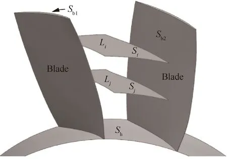
Fig. 2 A typical blisk model.
In the trochoidal milling process,the radial cutting depth is usually set to a small value while the axial cutting depth is set to a relatively large value to improve the machining efficiency.To mill a blisk channel Γ,it is divided firstly into n layers{L1,L2, ..., Ln} according to the tool loads and the machined surface deviation. Trochoidal paths are generated for each layer and materials within Γ are machined layer by layer. The tool loads in terms of cutting force, toque and power25are constrained to avoid tool breakage in the machining process.The machined surface deviation is introduced by the approximation between the blade surface of Γ and the tool swept envelope.26Both aspects are already well documented, and this research will only focus on the trochoidal toolpath planning for each layer.
To generate toolpath for layer Li, an offset surface Sifrom Shis created and trimmed by the offset surface of Sb1and Sb2.The offset distance do=rc+δ, δ is the preset machining allowance for the rough milling process.After that,cutter contact points are planned in the parametric domain of Siand then mapped into the physical domain of Si.The mapping process can ensure that the toolpath covers the whole surface whether its shape varies or not, thus solving the problem of channel width variation. As for the tool orientation controlling, critical tool orientations on both sides of Siclose to Sb1and Sb2are determined first. Since the machining process is constrained to four-axis milling, there is a rotation plane parallel to the tool axis,and then tool orientations for other cutter contact points on Siare interpolated with two critical tool orientations on the same rotation plane. Finally, tool locations are calculated with generated cutter contact points and tool orientations.
3. Generation of cutter contact points
3.1. Cutter contact points generation in parametric domain
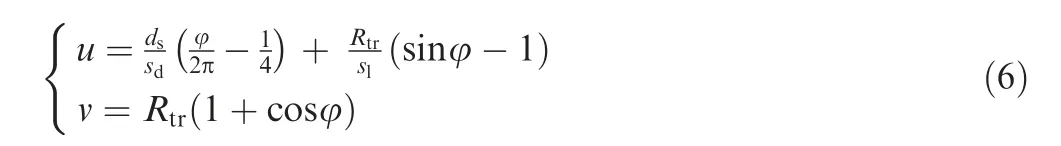
Considering a completely parametric surface Siin the parametric domain, u and v are the two parametric directions, as shown in Fig.3(a).c1and c2are boundary curves.To generate trochoidal paths in the parametric domain, Eq. (1) can be rewritten as

where dsis the maximum step over ahead of the trochoidal path, and Rtris the radius of trochoidal path. Surface Siis a completely parametric surface, and the parametric range is[0, 1]. The first item of the right part of u is used to control the maximum step over ds,and the second item is used to control the length dfin the feed direction, as shown in Fig. 3(b).
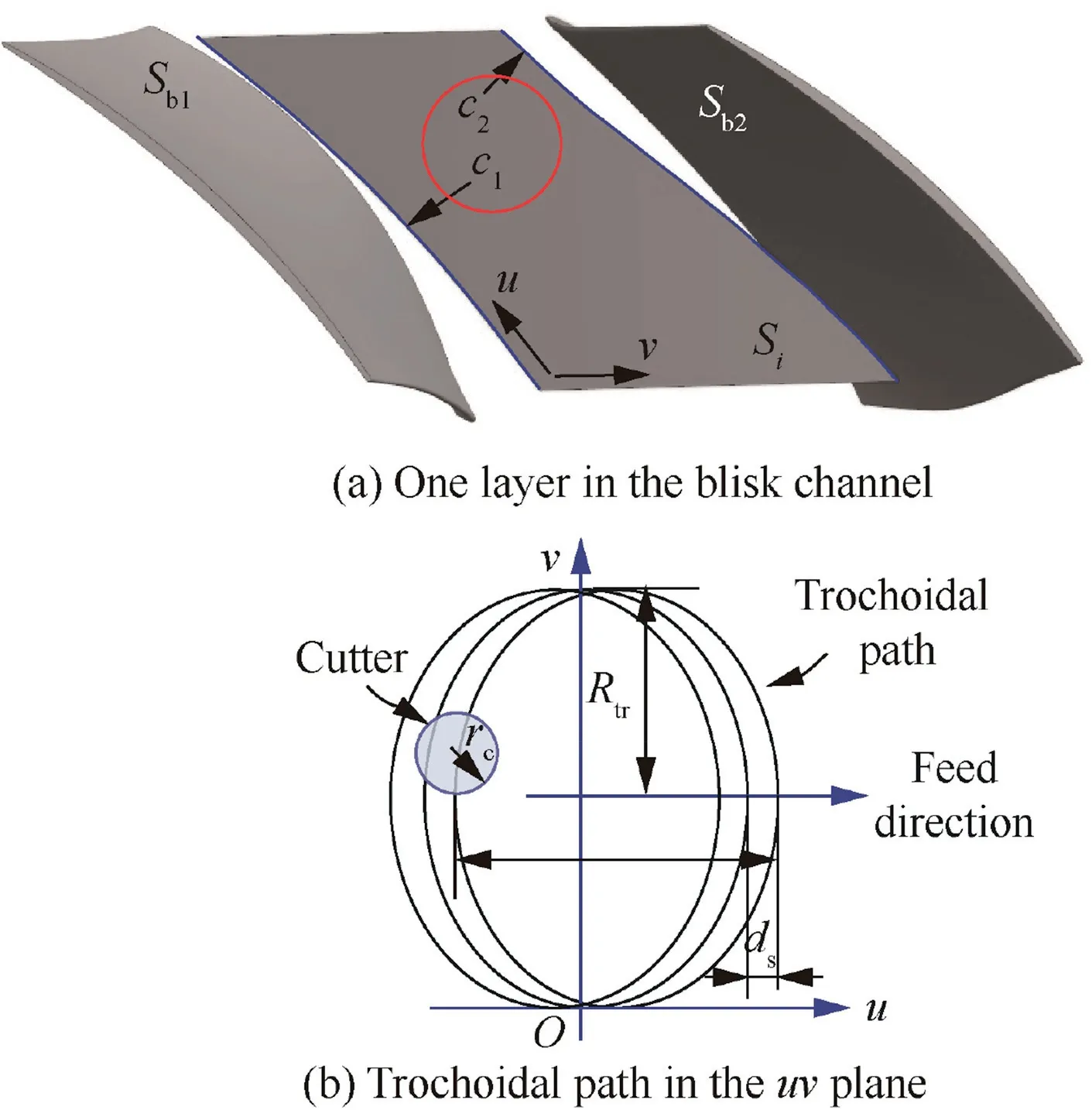
Fig. 3 Trochoidal path generation in parametric domain.
While we calculate points on the trochoidal path according to Eq.(2),the first cycle of the trochoidal path locates on both sides of the v axis,which means that the tool load may be very large for the first path.To overcome this problem,the path can be shifted left for distance δdto control the tool load along the first cycle of trochoidal path. Here the shifted distance δdis

With Eq. (4), all points in the parametric domain can be calculated. However, the generated trochoidal paths do not contain any information in the physical domain, and the stepover as well as the path width are not the same in the physical domain. Therefore, mapping method for paths from the parametric domain to the physical domain should be established.
3.2. Mapping between parametric domain and physical domain
The parametric domains for different completely parametric surfaces are the same, from 0.0 to 1.0. To transform paths from the parametric domain into the physical domain, a scaling factor sdis introduced to describe the distance mapping relationship between two domains and it is expressed as

where dphrepresents the corresponding value in the physical domain of dsin the parametric domain; dmaxis the designed maximum stepover in the physical domain and it determines the maximum radial cutting depth in trochoidal milling process. To control the length dfof a single trochoidal path cycle in u direction,a scaling factor slis introduced here.Given toolpath planning constraints in terms of the maximum stepover in the physical domain, the trochoidal paths in the parametric domain can be changed from Eq. (4) to the following form:
While slis set to be larger than 1.0,the length dfof a single trochoidal path cycle will be shortened. Given path planning parameters, including the maximum stepover and scaling factors, trochoidal toolpaths can be generated in the parametric domain with Eq.(6).With the increase of angle φ in the parametric domain, points expressed by (u, v) on the trochoidal path can be calculated. After that, points in the physical domain can be calculated according to the corresponding parameters (u, v) and can be expressed as

Since a ball-end cutter is used for the trochoidal milling,the ball center of the cutter will not change as long as the cutter contact point is determined. Therefore, tool orientations can be determined separately.
4. Tool orientation controlling method
The blisk channel Γ is usually narrow and the collision between the cutter and blade surfaces is easy to happen,which must be avoided in the milling process. Besides, since the feedrate for trochoidal milling is usually set to a large value,the machine tool axes move fast. Therefore, tool orientation change along the toolpath must be smooth enough to avoid the sudden change of tool load and path tracking error.27The tool orientation control methods for keeping smooth tool movement as well as the collision avoidance are discussed in this section.
4.1. Critical tool orientations
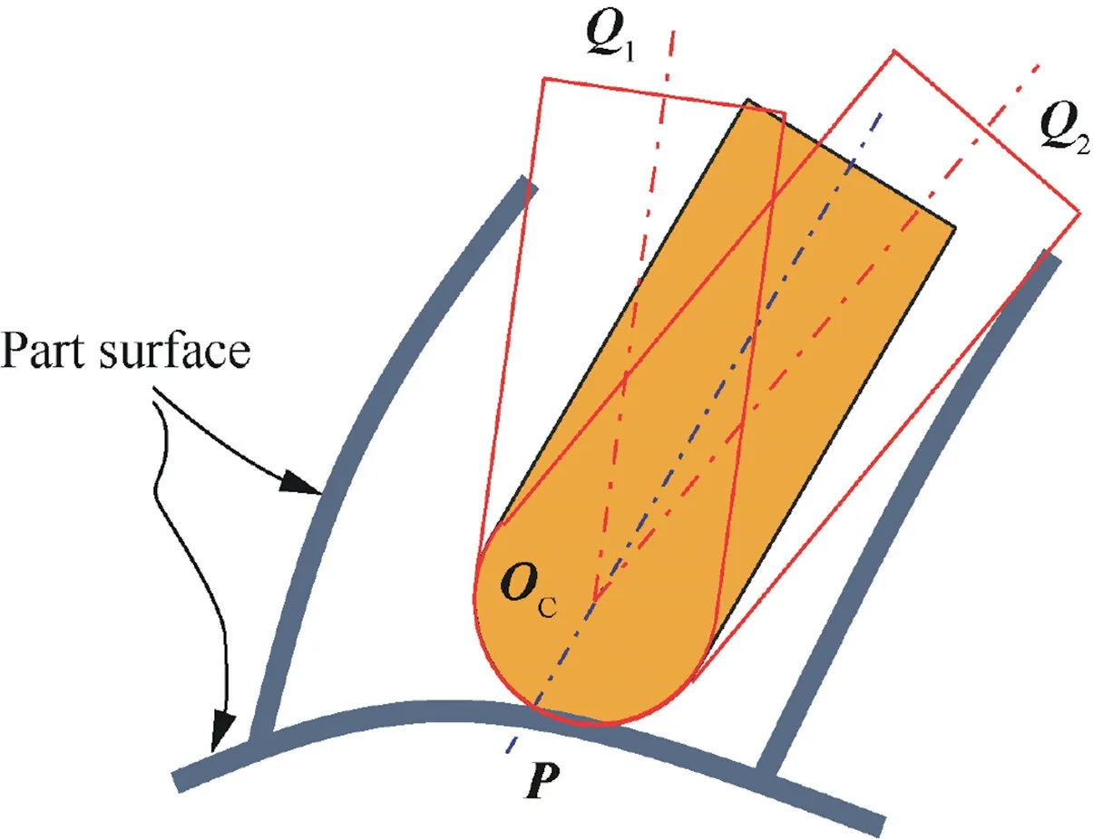
Fig. 4 Critical tool orientations.
To avoid collision between a cutter and the blade surface, the critical tool orientations (CTO) determination method developed in Ref.28is employed here. CTO represents the orientation in which the cutter is tangent to the check surface or machined surface. CTOs are determined at the most severe positions along the toolpath, such as the paths on both sides on the blisk hub surface close to the blade surfaces on both sides or clean-up paths for both blades.While tool orientations are beyond this CTO,there must be collisions between the cutter and the workpiece.As shown in Fig.4,while we mill point P on the toolpath,there are two CTOs expressed by OCQ1and OCQ2. No collision will happen as long as tool orientations falling between the two CTOs.
In the four-axis milling process, all tool orientations are in the plane perpendicular to the rotation axis. For each cutter contact point on the machined surface, it has two CTOs as shown in Fig. 4. The determination of CTO is a one-dimensional search problem. In the plane perpendicular to the rotation axis, there are two boundary points on the machined surface, and the initial CTOs are set as the normal vector of the machined surface at the two boundary points.Then, a two-stage searching strategy is used in the searching of CTOs. First, in the initial searching stage, a large searching step length is used to determine the searching range and then the Golden Section Search (GSS) is adopted to preliminarily determine a rough CTO. Then, an accurate searching is employed with a small deflection angle as the searching step length. The searching procedure is shown in Fig. 5.In real milling process, the trochoidal toolpath should be shifted left as mentioned in Section 3.1, thus the cutter is out of the surface to be machined during the tool approaching process, and in this case the blade surfaces and machined surface can be extended in preprocessing so that the aforementioned searching method of CTOs can be used.
4.2. Tool orientation interpolation for four-axis trochoidal milling
In four-axis milling process, all tool orientations are perpendicular to the rotation axis, as shown in Fig. 6. To generate tool orientations along the toolpath for four-axis trochoidal milling of a blisk channel, the quaternion interpolation (QI)algorithm is applied to guarantee the smooth change of tool orientations along the toolpath.
A quaternion consists of a scalar and a three-dimensional vector, which is defined as29

where xq,yq,zqare real numbers,w is the scalar part,and i,j,k are the quaternion units satisfying the conditions

A quaternion can also be expressed as q=[w, vq], where vector vq=xqi+yqj+zqk. Spherical QI algorithm is used in this study, and thus it will result in unit vectors on a unit sphere following the shortest part on it.
Given two tool orientations q1and qn,the spherical quaternion interpolation from q1to qnis defined as

Fig. 5 Searching procedure of CTOs.

Fig. 6 Tool orientation interpolation for four-axis milling.

where

If q1is close to qnand θ ≈0,the denominator in Eq.(10)is close to zero. In this case, the following formula can be employed:

According to Eq. (10), all endpoints of interpolated unit vectors will fall on the shortest arc. That is to say, all interpolated tool orientations are perpendicular to the rotation axis.
As shown in Fig.7,we consider a cutter contact point Pm,kto be machined on the ith layer surface Si(u, v). Let πkbe the rotation plane which is perpendicular to the rotation axis at point Pm,k. It has two intersection points Pc1,kand Pc2,kwith the two boundary curves c1and c2. Suppose Tc1,kand Tc2,kare the corresponding CTOs for Pc1,kand Pc2,k, and then tool orientation for point Pm,kcan be calculated with Eq. (10) and is expressed as

To relate the tool orientation change with the toolpath length, the parameter t in the above equation is defined as


Fig. 7 Tool orientation interpolation.
where sk,1crepresents the arc length from Pc1,kto Pm,k, and sk,12represents the arc length from Pc1,kto Pc2,k.
5. Simulation and experimental validation
The developed four-axis trochoidal toolpath generation method for the rough milling of an open blisk has been implemented, and both computer simulation and physical cutting experiments are conducted. The test model is a typical blisk channel formed by two neighboring blades as shown in Fig.8,and the depth of the layer is around 32 mm.To remove most of the materials in the channel, two layers of four-axis trochoidal milling toolpaths are generated, the depth for each layer is about 16 mm,and the maximum stepover between trochoidal paths is set to 1.0 mm.The tool used here is a ball-end cutter with 10 mm diameter and four flutes. The toolpath length is 2317 mm for the first layer and 1936 mm for the second layer.To avoid collisions between the cutter and the workpiece, a solid model with the machining allowance is used to determine the CTOs for the first layer. After that, the inprocess workpiece4of the first layer is then used to determine the CTOs for the second layer.
Machining simulation results are shown in Fig.9.From the in-process simulation, it can be seen that both flank edges and spherical edges are involved in cutting. Besides, the cutterworkpiece engagement (CWE) region is along the tool axis direction, and the radial cutting depth as well as the tool immersion angle are small. In this case, the tool can have enough time to be cooled and its service life can be prolonged.19,30
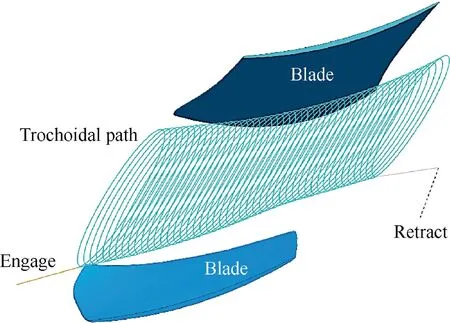
Fig. 8 Generated trochoidal toolpath and interpolated tool orientations.
To validate the trochoidal toolpath,physical cutting experiments were conducted with a four-axis vertical machining center YHVT850Z. Since the example is only used for demonstrating the validation of trochoidal milling toolpath generation method,only an aluminum alloy workpiece is used in this study.The spindle speed is set to 3000 r/min with in-cut feedrate 300 mm/min.Machining results are shown in Fig.10,and the blisk channel is well machined by the generated trochoidal toolpath. For practical aero-engine blisks, they are usually made of hard-to-cut materials including Titanium alloy31,32and Ni-based super alloy.33Previous work has demonstrated that large axial depth of cut can be reached in trochoidal milling of hard-to-cut material.14Therefore, the developed trochoidal toolpath planning method can be employed for blisks mentioned above with proper cutting parameters.
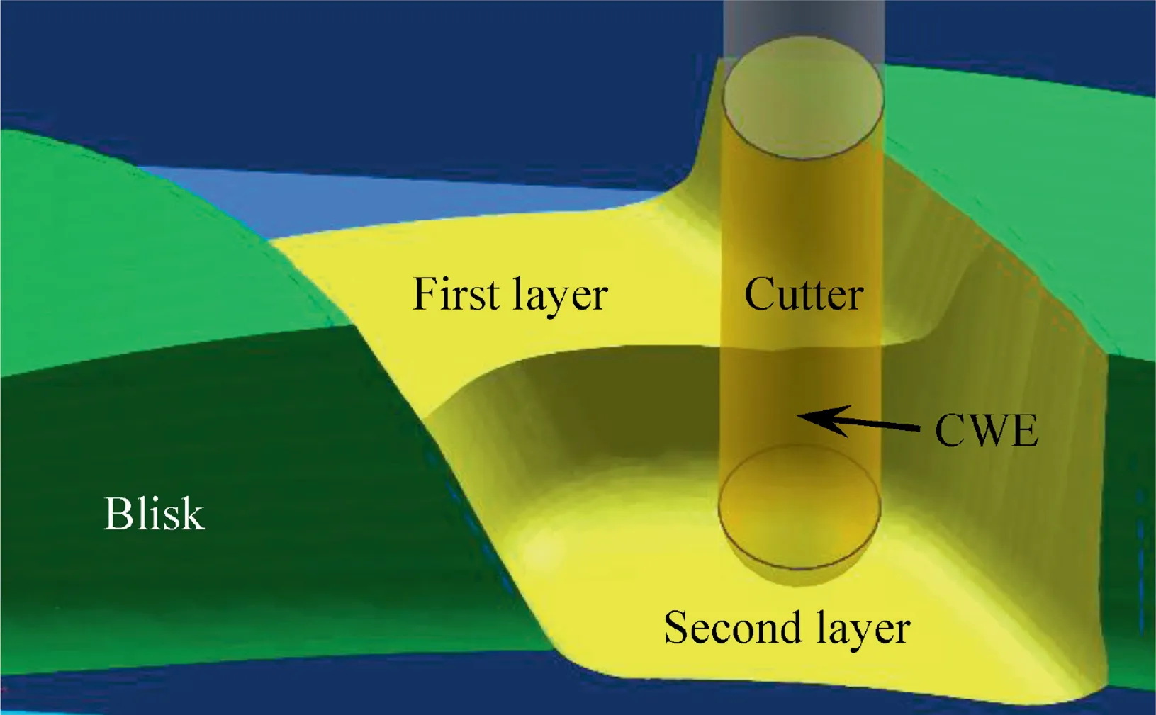
Fig. 9 Trochoidal milling process simulation.

Fig. 10 Trochoidal rough milling results.
6. Conclusions
In this paper,a four-axis trochoidal toolpath planning method for rough milling of aero-engine blisk with ball-end cutter is proposed, including the generation of cutter contact points as well as the tool orientation controlling.Cutting experiments with two layers of trochoidal toolpaths validate the proposed method. The developed trochoidal toolpath generation method can be further extended to five-axis rough milling and different cutters including the tapered ball-end cutter and bull-end cutter. The main contributions of this paper can be concluded as follows:
(1) Trochoidal toolpaths are generated in the parametric domain and then mapped into the physical domain to get width-fit paths, and scaling factors are introduced to control the stepover between neighboring trochoidal paths.
(2) Tool orientations are controlled by using critical orientations and combining with quaternion interpolation method to have smooth tool movement during the machining process.
Therefore, the developed trochoidal toolpath generation method could be directly used in the workshop for the fouraxis rough milling of an open blisk. Further research which includes controlling of uncut chip thickness along tool axis in multi-axis trochoidal milling as well as optimization of cutting parameters to reduce tool wear rate in trochoidal milling of hard-to-cut materials will be carried out.
Acknowledgements
This study was supported by the China National Science and Technology Major Project (No. 2015ZX04001202).
杂志排行

CHINESE JOURNAL OF AERONAUTICS的其它文章
- Special Column of BWB Civil Aircraft Technology
- Assessment on critical technologies for conceptual design of blended-wing-body civil aircraft
- Exploration and implementation of commonality valuation method in commercial aircraft family design
- Effects of stability margin and thrust specific fuel consumption constrains on multi-disciplinary optimization for blended-wing-body design
- Nacelle-airframe integration design method for blended-wing-body transport with podded engines
- On developing data-driven turbulence model for DG solution of RANS