Impact point prediction guidance based on iterative process for dual-spin projectile with fixed canards
2019-09-28XinZHANGXiaoxianYAOQiushiZHENG
Xin ZHANG, Xiaoxian YAO, Qiushi ZHENG
School of Aerospace Engineering, Beijing Institute of Technology, Beijing 100081, China
KEYWORDS
Abstract The fixed canards configuration of a dual-spin projectile makes it difficult to apply the traditional guidance law.In this study,a modified impact point prediction guidance strategy based on an iterative process was developed for a class of dual-spin projectiles with fixed canards, to reduce the impact point dispersion. The guidance strategy is dependent on the modified projectile linear theory to rapidly predict the flight states and the impact point. For projectiles with control applied to the trajectory, the modified projectile linear theory method is known to achieve poor impact point prediction.To improve the prediction accuracy,improvements were made to the modified projectile linear theory by considering the products of the yaw rate and other small quantities.The guidance strategy is based on the iterative process for the continuous adjustment of the expected output of the roll angle of the course correction fuze, to minimize the direction error between the predicted impact point and target location. Studies were conducted on a model dual-spin projectile configuration to demonstrate the guidance details. The numerical simulations indicate that the proposed guidance strategy can effectively reduce the projectile impact point dispersion.
1. Introduction
Given that a higher delivery accuracy and low collateral damage of future artillery projectiles is an important objective,the Course Correction Fuze (CCF)1,2concept has received significant research attention in recent years. The dual-spin concept3,4involves a type of projectile that can be divided into two parts with different roll rates: the forward body and after body. The forward body is de-spun to a low or opposite roll rate after the launch, whereas the after body maintains a high roll rate. To reduce the CCF cost and complexity, a fixed canards design is proposed. The fin deflection angles of the dual-spin projectile with fixed canards are constant, which implies that the control force magnitude is uncontrollable and the control force orientation is determined by the roll angle of the forward body. Traditional guidance laws are difficult to apply in such cases.
Projectile linear theory is a series of simplifications of the equations of motion which allows closed-form solution of the projectile trajectory under restricted flight conditions.And the closed-form solution is used to predict the impact point and other flight states. Projectile linear theory has been extended by various authors in the last years. Linear theory of a dual-spin projectile in atmospheric flight was developed in Ref.5. A modified version of the projectile linear theory was proposed as a rapid projectile impact point predictor that improves accuracy while preserving low computational requirements in Ref.6.Closed-form expressions for the swerving motion were obtained under the action of lateral pulse jets by using the projectile linear theory for a dual-spin projectile in atmospheric flight in Ref.7. The projectile linear theory for spinning projectiles was extended to consider the application of a simple lateral square impulse, activated during free flight in Ref.8.A real-time,in-flight impact point prediction method for an indirect fire projectile was investigated in Ref.9.A combination of the modified projectile linear theory and Kalman filtering can predict the impact point in flight successfully.Refs.10,11adjusted the modified linear theory to consider vertical velocities and pitch rates in order to improve the prediction accuracy even at very low speeds, and the epicyclic equations were separated into longitudinal and lateral equations by considering the small roll rate.

Nomenclature α,β angles of attack and sideslip in the fixed plane reference frame θ,ψ Euler pitch and yaw angles ρ air density ρa distance between composite mass center and after body mass center ρf distance between composite mass center and forward body mass center φF,φA Euler roll angles for the forward and after bodies cR rolling friction coefficient for bearing cV viscous damping coefficient for bearing CFD drag force coefficient for the forward body CFl p roll damping moment coefficient for the forward body CFLα lift force coefficient for the forward body CFM α static moment coefficient for the forward body CFMpα Magnus moment coefficient for the forward body CFMq damping moment coefficient due to the pitch rate for the forward body CMδ control moment coefficient for the pair of steering canards CNδ normal control force coefficient for the pair of steering canards CFy pα Magnus force coefficient for the forward body g gravity acceleration IAx mass moment of inertia matrix of the after body with respect to the after body frame IFx mass moment of inertia matrix of the forward body with respect to the forward body frame IFy,IAy transverse moment of inertia for the forward and after bodies l,S reference length and area m total projectile mass mF,mA mass for the forward and after bodies pA,pF roll axis components of the angular velocity vector of the after and forward bodies q,r components of the angular velocity vector of both the forward and after bodies u,v,w translation velocity components of the composite center of mass V magnitude of mass center velocity x,y,z position vector components of the composite center of mass expressed in the inertial reference frame
Numerous other methods for impact point prediction and projectile identification have also been proposed in the literature12-17. Based on impact point prediction, various guidance and control strategies have been studied. A unique control law that combines linear projectile theory and model predictive control for the lateral pulse jet control of an atmospheric rocket was reported in Ref.18. The projectile linear theory was used to map the projected impact point in the vertical target plane, and the control action was based on the projected miss distance and direction.Ref.19developed an impact point model predictive control method for a spin-stabilized projectile with instability protection. An ellipse fit method was used to calculate the required lateral control force angle.Stability protection control logic was applied to prevent the projectiles from experiencing instability. Ref.20developed a predictive guidance algorithm for a spin-stabilized,hit-to-kill interceptor.A new high-quadrant-elevation trajectory predictor and target acquisition system were used in the system. Lateral pulse jets located near the mass center were used as control mechanisms.
Given the discussion above, this paper proposes a novel guidance law for the control of dual-spin projectiles with fixed canards through the application of impact point prediction guidance based on an iterative process. The basic dual-spin projectile configuration under consideration is spin-stabilized,and the fixed canards mounted on the forward body are used as the control mechanism.The fixed canards can provide pitch and yaw moments and swerve forces to the projectile;however,the control force magnitude is uncontrollable, and the control force orientation is determined by the roll angle of the forward body.It was assumed that the projectile states are all sensed or estimated by an onboard Inertial Measurement Unit (IMU).To improve the prediction accuracy of the modified projectile linear theory, corrections were made by considering the products of the yaw rate and other small quantities when control is applied to the projectile.Thereafter,the impact point with and without control can be rapidly and accurately predicted. The CCF roll angle instruction is updated in each computation cycle by the impact point prediction guidance controller, to minimize the direction error between the predicted impact point and target location by means of an iterative process.The guidance process details were evaluated using a model dual-spin projectile configuration. The Monte Carlo simulation results demonstrate that the impact point prediction guidance based on the iterative process can effectively reduce the projectile impact point dispersion.
The remaining part of the paper is organized as follows.The dual-spin projectile dynamic model is given in Section 2.Then, the trajectory prediction is conducted by using the corrected modified projectile linear theory in Section 3. In Section 4, the impact point prediction guidance system is introduced and analyzed. The simulation results are given in Section 5. Conclusions are drawn in Section 6.
2. Dual-spin projectile dynamic model
The dual-spin projectile with fixed canards discussed in this paper is illustrated in Fig. 1. The deflection angles of differential canards 1 and 3 are opposite and can provide a moderate roll rate of the forward body during flight. The deflection angles of steering canards 2 and 4 are the same and can be directed to provide a canard control force. The roll angle of the forward body is controlled by the motor in the CCF, for the generation of the required direction of the control force when the trajectory correction is required. Otherwise, the forward body rolls freely at 10-20 r/s opposite to the direction of the after body, due to the differential canards, and the trajectory is uncontrolled in this case.The key point of the trajectory correction is the determination process of the required roll angle of the forward body according to the trajectory information when trajectory correction is required.
The nonlinear dynamic model used in this study is a typical Seven Degree of Freedom (7DOF) model used in the flight dynamic modeling of dual-spin projectiles.The ground surface reference frame Oxyz is used as an inertial reference frame,while a fixed-plane reference frame21is used to describe the dual-spin projectile motion. The fixed-plane reference frame is attached to the projectile center of gravity, and will pitch and yaw with the projectile, but not roll. Its xFPaxis aligns with the projectile centerline and points forward out of the nose. Its positive yFPaxis points to the right, and its zFPaxis is perpendicular to the xFPand yFPaxes pointing downward.Both the forward and after bodies share the same frame before roll rotation,and the yFPaxis always remains in the Earth horizontal plane.
The equations of motion are provided in Eqs. (1)-(4).22A more general case was studied in Ref. 5.


Fig. 1 Dual-spin configuration.


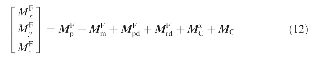
All the forces that act on the body can be expressed in the fixed plane reference frame. Moreover, the forces that act on the forward body can be expressed as follows:

The gravity GF, lift force LF, drag force DF, and Magnus force KFfor the forward body are as follows22:


Fig. 2 Deflection of canards (viewed from rear).

The control forces are created by the fixed steering canards in the direction perpendicular to the symmetry axis of the projectile:
where δzis the constant deflection angle of the fixed steering canards in the forward body frame, and the sign convention is demonstrated in Ref.23.
The applied moments that act on the forward body about the projectile mass center can be expressed as follows:

The roll moment due to the fixed differential canards, and the control moment due to the fixed steering canards can be expressed as follows:
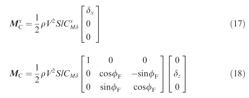
where δxis the constant deflection angle of the fixed differential canards in the forward body frame.
The expressions for the after body forces and moments have the same form as those of the forward body, with the exception of the control force and moment due to the canards.It should be noted that the drag force and damping moment induced by the canards are incorporated into the forward body forces and moments.
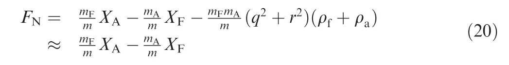
The remaining viscous damping and rolling friction moments can be expressed as follows5:

where FN| | is the absolute value of the normal force that acts on the bearing, and FN| | can be expressed as follows:
The dynamic equations provided by Eqs. (1)-(4) can be numerically integrated forward in time by using a fourthorder, fixed-step Runge-Kutta algorithm.
3. Corrected projectile linear theory trajectory prediction
The dual-spin projectile dynamic model consists of 13 highly nonlinear ordinary differential equations, and simplifications are required to estimate a trajectory. The projectile linear theory of a dual-spin projectile in Ref.5provided sufficiently accurate trajectory predictions for flat fire short trajectories.However, this method achieves a poor impact point prediction for long-range shots with high quadrant elevations characteristic of indirect fire munitions, such as the dualspin projectile discussed in this paper. To improve the trajectory prediction, the modified projectile linear theory was developed by altering the solution procedure and relaxing the typical assumption of the small Euler pitch angle. By using the modified projectile linear theory, a projectile impact point predictor was proposed in Ref.6for the rapid and accurate computation of the ballistic trajectory of a projectile. To develop the modified projectile linear theory equations, a set of simplifications were employed, as in Ref.6.The pitch and yaw rates q and r, and yaw angle ψ are assumed to be small, and the products of small values are treated as negligible. These simplifications are suitable for the uncontrolled ballistic trajectory. However, the estimation of the controlled impact point is an integral part of the guidance strategy proposed in this paper. When control is applied to the trajectory, the assumptions that q, r, and ψ are small could result in significant impact point prediction errors, given that the dynamic responses and steady states of q, r, and ψ under control are not small in magnitude.To improve the controlled trajectory prediction, the modified projectile linear theory was corrected to relax the assumption of the small pitch and yaw rates q and r, in addition to the yaw angle ψ. Accordingly, the products of q, r, and the small quantities are considered in the epicyclic equations when compared with the modified projectile linear theory,and more accurate numerical integration methods were selected to solve the Euler angle and swerve equations.
The arc length s is dimensionless and expresses the projectile downrange travel in calibers:
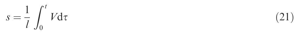
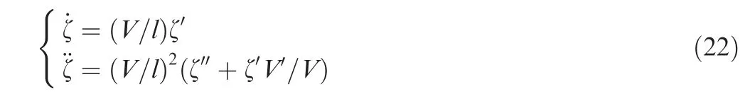
Eq. (22) expresses the relationships between the time derivatives and arc-length derivatives with respect to an example variable ζ, where the prime terms are used to denote the arc-length derivatives and the dotted terms denote the time derivatives:
Applying the modified projectile linear theory to the equations of motion yields:

The closed-form solutions of Eqs.(23)-(34)can be obtained by making additional assumptions as in Ref.6.At each prediction step:
(A) The aerodynamic coefficients are constant.
(B) The total velocity V slowly changes in relation to the other variables. It is only treated as a dynamic variable in the solution of the total velocity Eq. (35).
(C) The roll rate pAslowly changes in relation to the other angular rates. It is treated as a dynamic variable in the solution of the roll rate equation, but as a constant in the solution of the epicyclic equations.
The total velocity V,the aerodynamic coefficients and other coefficient values which are slowly changing with relation to the other variables are only treated as constant in the closedform solution at each prediction step.The trajectory prediction method uses the closed-form solution of the system to propagate the states forward and the prediction step is also marched forward. In this process, the last trajectory point predicted is treated as the initial conditions for the new prediction step.Before the new prediction step is computed, all constants in the model are recomputed using the new initial condition data.Therefore, the model is periodically updated along the trajectory. Similar to the modified projectile linear theory solution,the total velocity, roll rate, epicyclic equations, Euler angle,and swerve solutions are expressed as follows. These solutions are used to predict the ballistic and controlled trajectory states in the impact point prediction guidance system.
3.1. Total velocity solution
The total velocity solution is obtained by considering the pitch angle as a constant, and then integrating Eq. (29):

where

3.2. Roll rate and Euler roll angle solution
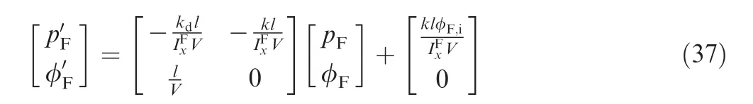
The required roll angle of the forward body in the guidance is defined as the control input φF,i.The roll angle of the forward body φFis controlled to track the control input φF,iby the motor in the CCF when trajectory correction is required.The control loop for the roll angle of the forward body is illustrated in Fig. 3. Moreover, ε is the complex variable of the Laplace transform. In Fig. 3, M is defined as M=MFx+MS+Me, where Meis the motor torque. It is assumed that full state feedback is available in the control law. In particular, x, y, z, φF, φA, θ, ψ, u, v, w, pF, pA, q,and r are sensed or estimated by the IMU. It is then assumed that MFxand MScan also be estimated. Thus, the rotational dynamic equations of motion for the forward body can be expressed as IFx˙pF=M. The rtanθ term can be eliminated by adding a -IFx(rtanθ)′term to the roll angle controller output.Under the assumption that the roll angle controller can be designed as an ideal Proportional-Integral-Derivative (PID)controller, which has a transfer function of k+kdε; Eq. (37)can be obtained when φF,iis a constant input.The focus of this paper was not the design of the roll angle controller; thus, the control logic was simple,and various assumptions were made.
The Laplace transform of Eq. (37) can be expressed as
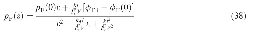
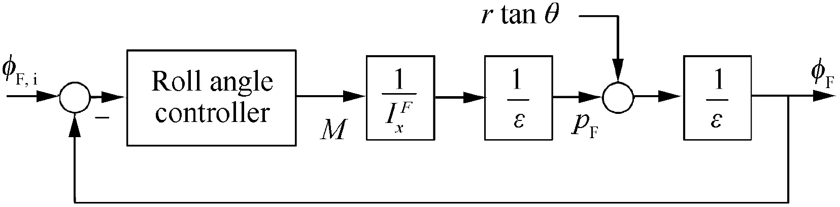
Fig. 3 Forward body roll angle control system diagram.

The Laplace inverse transform of Eqs. (38) and (39) is expressed in Eqs.(40) and(41).The expressions for the coefficients expressed in Eqs. (40) and (41) are not included here.These coefficients are algebraic equations that can easily be evaluated using computer code.

The effect of the motor torque on the roll rate of the after body pAcan be ignored, as mA≫mFand pA≫pF. The roll rate of the after body solution is determined by integrating Eq. (32):

3.3. Epicyclic solution
According to the modified projectile linear theory,the epicyclic solution can be expressed as follows:
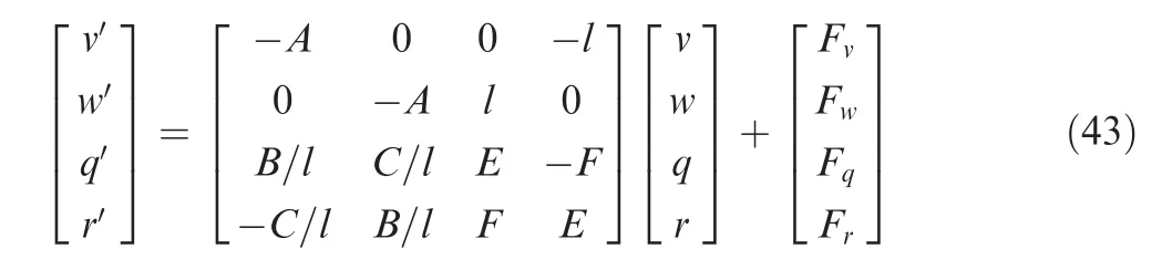
The coefficients in Eq. (43) can be expressed as follows:

The products of ˙φFPand small quantities are neglected in Eq. (43), according to the modified projectile linear theory.For the uncontrolled ballistic trajectory, q and r are small,and the products of small values and derivatives of small values can be treated as negligible.When control is applied to the trajectory, the magnitudes of the pitch and yaw rates q and r cannot be treated as small. Therefore, the modified projectile linear theory is corrected, and a correction term Q0that considers the products of q and r,in addition to other small quantities, is added to Eq. (43):

where

The subscript 0 in all the terms of Q0indicates that these terms are treated as constants in a step length. The computed results of the last step are considered as the initial conditions for a new step. The φFin Fv, Fw, Fq, and Frterms are considered similarly. The closed-form solutions of Eq. (53) can then be expressed as follows.24The expressions for the coefficients in Eqs. (55)-(58) are not included here. These coefficients can easily be evaluated using computer code. The detailed treatment of the solutions can be found in Ref.7. From the consideration of the correction term Q0, the proposed corrected modified projectile linear theory method can eliminate the accuracy problems when control is applied to the trajectory, while preserving low computational requirements.

3.4. Euler angle and swerve solution
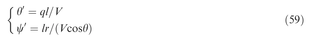
In the modified projectile linear theory,the integral is approximated by the trapezoid method to obtain the solutions of the Euler angle and swerve equations, and ψ is treated as small.When control is applied to the trajectory, ψ cannot be regarded as small; otherwise, errors appear in the solutions of the swerve equations. In this paper, the closed-form solutions of the Euler angle and swerve equations were not required in the guidance strategy. Thus, ψ was not treated as small, and the more accurate fourth-order fixed-step Runge-Kutta algorithm was used to obtain the numerical solutions of the Euler angle and swerve equations.Other numerical integration methods can also be used to simplify the calculation.The Euler angle and swerve equations can therefore be expressed as Eqs.(59)and(60).The solution of φAis not provided here, as it is not required in the guidance strategy.

3.5. Comparison between prediction results
The simulated projectile was a typical 155 mm dual-spin projectile with fixed canards. The main parameters of the dualspin projectile and initial conditions are presented in Section 5.After the launch, the projectile was uncontrolled before 70 s,which implies that the forward body rolled freely with a low roll rate opposite to that of the after body.Thereafter,the control input was set as φF,i=90°at 70 s, and then maintained until the end of the flight.The comparison between the prediction results generated by the conventional projectile linear theory in Ref.5,the modified projectile linear theory in Ref.6,and the corrected modified projectile linear theory in this study is presented with respect to a dimensionless arc length of 2000 after 70 s. The three linear theory trajectories were computed using a dimensionless arc length step size of 1.The 7DOF solutions were computed as the truth model using the fixed-step Runge-Kutta method with a time step size of 0.001 s.The variations in the total velocity V and the main aerodynamic coefficients were plotted as shown in Figs. 4 and 5, respectively.The total velocity V and the aerodynamic coefficients are slowly changing with relation to the other variables, and can be considered as constant at each prediction step.
Fig.6 illustrates the results for the roll angle of the forward body with respect to the dimensionless arc length for the 7DOF, modified projectile linear theory, and the corrected modified projectile linear theory methods,where M.L.denotes the modified linear in the figure. When the control input was set as φF,i=90°at 70 s,the controlled roll angle of the forward body could effectively track the control input. No differences between the φFpredictions of the three methods were observed, and the conventional projectile linear theory results are not presented. Thus, the prediction results adequately tracked the roll angle predicted by the 7DOF method.
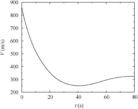
Fig. 4 Variation in the total velocity V with respect to time.
Figs.7 and 8 present comparisons between the v,w,q,r,θ,and ψ results predicted by the three methods,where L.denotes the conventional projectile linear theory. The figures reveal that the prediction results of the corrected modified projectile linear theory were more accurate than those of the conventional projectile linear theory and modified projectile linear theory. There was an increase in the prediction errors of the conventional projectile linear theory and modified projectile linear theory in accordance with an increase in the dimensionless arc length of the prediction, especially in the θ and ψ predictions.The main contributing factor to the inaccuracy of the standard modified projectile linear theory was the neglect of the products of ˙φFPand small quantities.Moreover,significant prediction errors were observed with the typical assumption of a small Euler pitch angle in the conventional projectile linear theory.

Fig. 5 Variation in the main aerodynamic coefficients with respect to time.

Fig. 6 φF with respect to dimensionless arc length.
The range and cross range trajectory prediction results are illustrated in Fig. 9. The corrected modified projectile linear theory predicted the trajectory with an adequate accuracy,whereas the conventional projectile linear theory and the modified projectile linear theory achieved poor impact point predictions. For high quadrant elevation shots, there were significant impact point prediction errors using the conventional projectile linear theory,due to the assumption of a small Euler pitch angle. Through the modifications of the modified projectile linear theory, the proposed corrected modified projectile linear theory method eliminates the accuracy problems of the other methods, while preserving low computational requirements when control is applied to the trajectory. Moreover,it was employed in the following impact point prediction guidance system.

Fig. 7 Velocity and angular velocity components with respect to the dimensionless arc length.
4. Impact point prediction guidance system
Due to the fixed canards, the control force magnitude is uncontrollable,and the control force orientation is determined by the roll angle of the forward body. Therefore, it is difficult to apply traditional guidance laws that require a continuous adjustable control force, such as the proportional navigation guidance law, to the guidance of the dual-spin projectile with fixed canards. A control method based on the period average25,26can be used to regulate the average control force value of the dual-spin projectile with fixed canards; however, it imposes severe demands on the actuator performance. The impact point prediction control is based on the prediction of the impact point in flight, in each computation cycle of the guidance law,for the determination of the control input for the impact of the target. Impact point control is a very powerful and useful methodology for the control of guided dual-spin projectiles with fixed canards,as this type of control is applicable to guided projectiles in which the control authority is small,and control is achieved by effectively correcting the projectile towards the target.
A key point of the impact point control is the establishment of the mapping from the control input to the controlled impact locations. As in Ref.27, the angle between the control angle and swerve response is known as the phase shift. Common methods for calculating the phase shift, as in Refs.27,28, are based on solving the differential equation for the complex angle of attack,which is achieved by using the projectile linear theory. However, the phase shift is obtained from the yaw of repose under control,which is the steady state solution.Therefore, the guidance law computation cycle must be longer than the convergence time for the deviation of the phase shift that reaches the steady state; otherwise, errors will occur in the guidance.However,a lengthy guidance law computation cycle also results in errors in the guidance.The typical guidance and control design of dual-spin projectiles, as in Ref.27, does not consider the above problems.
Therefore, similar to pulse-jet control, a guidance strategy known as impact point prediction guidance based on the iterative process is developed. The similarity is that the impact point prediction guidance based on the iterative process is also a discrete control method. In particular, when correction is required,the control input is updated in each guidance computation cycle,and then maintained until the next cycle.An iterative process was designed to determine the control input for minimizing the direction error between the predicted impact point and target location. Thus, the key to the guidance strategy is that the phase shift is eliminated by the iterative process using impact point prediction. The computation cycle is not limited by the convergence time of the projectile dynamic response, and the correction accuracy is improved.
4.1. Trajectory correction mechanism
The dynamic response of the dual-spin projectile to canard control was initially evaluated to determine the trajectory correction mechanism by applying the modified projectile linear theory. Two first-order complex differential equations can be derived from Eq. (43) as follows:

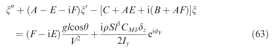
For a constant roll angle φF,the yaw of repose ξC,Rinduced by canard control can be obtained using Eq. (63)

where

The complex normal overload ncdue to the fixed steering canards is obtained from Eqs. (8) and (11)

where ncindicates the swerve response direction of the projectile under control. The mapping from the control input φFto ncestablished by Eq. (66) is the steady state solution. The traditional guidance strategy for dual-spin projectiles with fixed canards as in Ref.27was designed by estimating this mapping.In the next subsection,the mapping from the control input φFto the controlled impact locations considering the projectile dynamic response is established by the iterative process.
4.2. Guidance strategy
The impact point prediction controller uses the predicted system states to propagate forward in time. The general form of the control system is illustrated in the block diagram in Fig. 10. It was assumed that full state feedback is available in the guidance; i.e., the states are all sensed or estimated by the IMU. The target information is loaded into the guidance system before the launch, where tutis the computation cycle length, which is also referred to as the guidance update time.The controller computation time is small when compared with tutand it was assumed that the computation time can be neglected in the following simulations. In each computation cycle, the impact point prediction guidance system updates the control input φF,iand maintains it until the next cycle.The forward body roll angle control system controls the roll angle of the forward body to track the control input.

Fig. 10 Control system.

The impact point prediction guidance system uses an iterative process to obtain the control input φF,iin each computation cycle. The iterative process is illustrated in Fig. 12, and the angles in the iterative process are defined in Fig. 13. The control action in each computation cycle is determined by minimizing a quadratic cost function,which is defined as Eq.(68).Minimizing the cost function J implies that the control input steers the predicted impact point toward the target.


Fig. 11 Magnitude geometry in the x-y plane.
Fig. 12 Flowchart of control system.


Due to the relationship between the roll angle of the forward body and control force direction in Fig. 2, the initial value of the control input in the iteration is set as φF,i,0=Δ0+π/2,which indicates that the control force points to T,as shown in Fig.13.The counter n is incremented by 1 in each iteration.In the nth iteration,the controlled impact point Bnis predicted with the control input set as φF,i,n-1.Thereafter,Bnis regarded as a target point, similar to T, and the phase error Δnon the yFP-zFPplane between B0and Bnis calculated in the same manner as Δ0.The control error angle is defined as φd,n=Δn-Δ0, and φF,i,nis updated as φF,i,n=φF,i,n-1-φd,n.In this case, φd,nis the actual error between the swerve response direction and target location. The exit criterion for the iteration is J <Jthor n ≥N, where J <Jthindicates that the value of the quadratic cost function is sufficiently small for the guidance, and n ≥N is the limit of the number of iterations. If the exit criterion is satisfied, the iteration is stopped and φF,i=φF,i,nis considered as the control input for this computation cycle; otherwise, the iteration continues. Thus, the control input required to move toward the target is obtained by the iteration. The mapping from the control input to the controlled impact locations under the consideration of the projectile dynamic response is established in the iterative process.The control input is calculated each time the guidance system is called. Further details on the guidance process are provided in Section 5.
5. Simulation results
To demonstrate the control logic described in Section 4,a typical 155 mm dual-spin projectile with fixed canards was considered in this study. The main parameters of the dual-spin projectile are listed in Table 1. To describe the uncertainty of the launch conditions, the initial launch location, pitch and yaw angles, pitch and yaw rates, and body velocities were all considered to be normally distributed random numbers with means and standard deviations that are representative of actual launch uncertainties. The selected values are listed in Table 2.
Table 1 Physical properties of 155 mm dual-spin projectile.

Table 2 Initial condition uncertainty parameters for dispersion analysis.
The standard trajectory was selected as that which the projectile would follow in the absence of uncertainty, with the mean values in Table 2 selected as the initial conditions. The target location was set as the desired impact point; i.e., the standard trajectory impact point, with x=21946.877 m and y=434.687 m. Fig. 14 presents the typical dispersion results for 50 sample trajectories with no control applied and initial condition perturbations, as shown in Table 2. The Circular Error Probable (CEP) centered at the target indicated in the figure was based on a 50% hit criterion, which implies that the CEP is defined as the minimum radius of a circle centered at the target location,and that it contains a minimum of 50% of the impact points. The CEP without control was approximately 206 m, as illustrated in Fig. 14.
Several simulations were conducted to demonstrate the projectile correction authority. The mean values in Table 2were selected as the initial conditions. Thereafter, the roll angle of the forward body was set as the designed constant roll angle from the control start time until the impact of the projectile with the ground for each simulation. The control start time varied from 40-80 s with a step of 5 s. The results are illustrated in Fig.15.When control was initiated at 40 s,the largest down-range correction authority from a distance far away to the target was approximately 570 m,and from a distance close to target,it was approximately 620 m;whereas the lateral correction authority was approximately 600 m. The control authority decreased in accordance with an increase in the start time delay of the control. In the following simulations, guidance was initiated at 40 s, to obtain a sufficient correction authority.

Fig. 14 Uncontrolled dispersion (CEP=206 m).
Fig. 15 Correction authority.

Fig. 16 Controlled dispersion.
A representative trajectory was selected from the controlled dispersion results presented above, to evaluate the details of the guidance. The controlled trajectory was plotted, as shown in Fig.17,with the standard and uncontrolled trajectories.The trajectory correction was significant after the initiation of control.The impact points of the uncontrolled and controlled trajectories were x=22087.93 m and y=7.61 m, and x=21945.33 m and y=434.59 m, respectively. The distance error of the uncontrolled impact point was 449.77 m,whereas the distance error of the controlled impact point was 1.55 m.
Fig. 17 Three-dimensional trajectories.

Fig. 18 Two-dimensional error trajectories.

Fig. 19 Details on end of error trajectories.
The two-dimensional error trajectories are illustrated in Figs.18 and 19.The ballistic error was obtained by subtracting the x and y coordinates of the standard trajectory from the x and y coordinates of the ballistic trajectory, with the same z coordinate at each instance.The end-point of the ballistic error curve represents the distance error between the ballistic impact point and target. The real error was obtained by subtracting the x and y coordinates of the standard trajectory from the x and y coordinates of the controlled trajectory,with the same z coordinate. The prediction ballistic error was obtained by subtracting the x and y coordinates of the standard trajectory from the x and y coordinates of the predicted ballistic trajectory,with the same z coordinate.All the error trajectories were initiated at 40 s and ended when the projectile impacted the ground (at approximately 82 s). The error between the start point of the prediction ballistic error trajectory and endpoint of the ballistic error trajectory was the impact point prediction error at the start of guidance. The magnitudes of the real error and prediction ballistic error decreased in accordance with an increase in the flight time due to the guidance.Fig. 19 presents the details near the end of the real error and prediction ballistic error trajectories. The real error trajectory converged to the end-point of the prediction ballistic error trajectory,whereas the magnitude of the prediction ballistic error almost converged to 0, due to the guidance.
Fig. 20 Iteration numbers with respect to time.

Fig. 21 φd with respect to time.

Fig. 22 Prediction ballistic distance error with control with respect to time.
Fig. 23 Prediction ballistic distance error without control with respect to time.

Fig. 24 φF and φF,i with respect to time.


Fig. 25 α and β with respect to time.

Fig. 26 Controlled dispersion results with respect to the control update time.
The final study revealed the effects of the length of the computation cycle tuton the CEP. In this case, tutwas set to vary from 0.5-7 s with a step of 0.5 s, and 50 Monte Carlo simulations were conducted for each tut, with the initial conditions set as shown in Table 2. The results were plotted, as shown in Fig. 26. The figure illustrates that the CEP is dependent on tut. This is reasonable, as a smaller tutresulted in a more rapid and accurate update of the control. However, tutcannot be set excessively small due to the limited actuator response frequency. For example, the typical settling time of the roll angle control system of the forward body was 0.1 s. Thus, the smallest tutused in this study was 0.5 s.
6. Conclusions
In this study,a guidance method was developed for a dual-spin projectile with fixed canards by applying the corrected modified projectile linear theory and impact point prediction guidance based on an iterative process. The modified projectile linear theory was corrected for the case where control is applied to the projectile, and it was demonstrated that the rapid and accurate computation of the trajectory of the dualspin projectile can be achieved. The impact point prediction guidance system minimized the error between the direction of the predicted impact point and target location using an iterative process, and then the control input was calculated to move the controlled impact point towards the target.The guidance details were discussed with reference to an example of controlled trajectory. The simulation results confirm that the guidance strategy can effectively reduce the projectile impact point dispersion.
杂志排行

CHINESE JOURNAL OF AERONAUTICS的其它文章
- Special Column of BWB Civil Aircraft Technology
- Assessment on critical technologies for conceptual design of blended-wing-body civil aircraft
- Exploration and implementation of commonality valuation method in commercial aircraft family design
- Effects of stability margin and thrust specific fuel consumption constrains on multi-disciplinary optimization for blended-wing-body design
- Nacelle-airframe integration design method for blended-wing-body transport with podded engines
- On developing data-driven turbulence model for DG solution of RANS