Maximal admissible mode decision delay in terminal guidance
2019-09-28ShengwenXIANGTinhengLIWeiCHENHongqiFANQingFU
Shengwen XIANG, Tinheng LI, Wei CHEN, Hongqi FAN,*, Qing FU
a National Key Laboratory of Science and Technology on ATR, College of Electronic Science, National University of Defense Technology, Changsha 410073, China
b School of Science, University of Salamanca, Salamanca 37008, Spain
c Aviation Key Laboratory of Science and Technology on Airborne Guided Weapons, China Airborne Missile Academy, Luoyang 471009, China
KEYWORDS
Abstract Mode decision-maker is a critical component in the logic-based Integrated Estimation and Guidance(IEG)system.For the best possible estimation and guidance performance,the mode decision delay of the mode decision-maker should be limited to a range as small as possible. This paper presents a numerical method for computing the maximal admissible mode decision delay that varies with time-to-go.Particular attention has been paid to highly maneuvering target interception in terminal guidance. The results of this research offer useful guidelines for the design of the mode decision-maker in IEG systems.
1. Introduction
The interception of highly maneuvering targets has attracted great attention in the field of research.1-3In a realistic interception scenario,the state information is corrupted with noise and some state variables cannot be measured directly such as the lateral acceleration of the evader.Thus,the estimator becomes an essential element of the guidance system. In general, the maneuver of the evader is unknown and unpredictable; the estimation process is commonly described as a hybrid estimation problem. Typical methods can be divided into two types:Single-Model (SM) and Multiple-Model (MM).4,5In either case, the mode decision delay affects the performance of estimation seriously.5,6Meanwhile, Shinar and Turetsky pointed out that the estimation delay of target maneuver, especially the delay of lateral acceleration, is the main source of error in miss distance for Highly Maneuvering Target Interception(HMTI).7
Intensive efforts have been devoted to the design of a guidance law that would lessen the impact of the mode decision delay on guidance performance. Shinar and Shima proposed a new guidance law named DGL/C (DGL: differential game law) for compensating the estimation delay based on solving a delayed information pursuit-evasion game.8Meanwhile,Glizer and Turetsky took both the estimation delays of lateral acceleration and relative velocity into account and developed a new delayed information pursuit-evasion game guidance law(denoted by DGL/CC).9However, a single combination of estimator and guidance law cannot fit all feasible target maneuvers especially for HMTI problems.7The method of Integrated Estimation and Guidance (IEG), combining a highly precise narrow bandwidth estimator and an independent mode decision-maker to currently output the evader’s motion mode,has shown superiority in improving the homing accuracy and has attracted considerable attention in the past few years.1,2,10In particular, the logic-based IEG approach is one of the most promising algorithms.11
The mode decision delay, as a critical parameter of the mode decision-maker, should be minimized. Otherwise, the inaccurate estimation caused by mode mismatch would misguide the pursuer and degrade the interception performance significantly (if there is not enough time for the estimator to converge). Recently, to reduce the mode decision delay, some work has been performed based on radar and image seekers.12-14By integrating the signature information highly related to the target maneuver, the estimation delay has been effectively reduced (see Table 1).
The objective of this paper is to explore a method for measuring the limit of mode decision delay under the configuration of the IEG system.In our earlier work,we evaluated the error characteristics of state estimation and obtained the Mode Delay Upper Bound (MDUB) by constraining the state estimation error.15,16However,only the characteristics of the estimator but not the characteristics of terminal guidance, have been taken into account. As the unit of each component in the state vector was different,the derived MDUB did not have a well-defined physical meaning and was too loose to be directly applied in the design of a guidance system. In this paper, the state vector is first transformed into Zero-Effort Miss (ZEM) distance and then a more compact MDUB is obtained by constraining ZEM instead. Considering that it is difficult to obtain an analytic solution from the derived equation,due to the time-varying characteristics,a numerical calculation method is proposed.The resulting MDUB is renamed as the Maximal Admissible Mode Decision Delay (MAMDD).
2. Problem formulation
2.1. System model
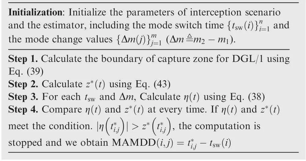
Table 1 Method for calculating MAMDD.
Our analysis is based on the widely used planar interception,7-9,15-17there are two players consisting of an interceptor (pursuer) and a target (evader), as shown in Fig.1.Let P and E denote the pursuer and the evader,respectively. Three common assumptions for planar interception are given in the following:
(1) The dynamics of P and E are evaluated by first-order transfer functions, with time constants τpand τe,respectively;
(2) Both P and E have constant speeds, denoted by Vpand Ve, respectively;

In Fig. 1, the x axis is established along the initial Line of Sight (LOS). (xp,yp) and (xe,ye) stand for the current positions of P and E. The aspect angles φpand φeare defined as the angles between the velocity vectors of the players and the positive X axis. Owing to the limited duration of terminal guidance and the high velocities of players,and assuming that φpand φemeet the small angle conditions (i.e.,sinφp≈φp, sinφe≈π-φe) after the adjustment of midcourse guidance, the trajectories is able to be linearized along the initial LOS.16Given an initial relative distance r0and supposing that the initial time t0=0 s,then the final time tfof the interception is approximated as

and the time-to-go of interception is defined as tgo=tf-t,where t ∈[0,tf].


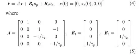
where x1=ye-ypis the distance of the evader relative to the pursuer along the Y axis; x2is the relative lateral velocity; x3and x4are the respective lateral accelerations; upand ueare the bounded acceleration commands, satisfying
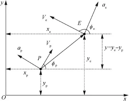
Fig. 1 Planer interception geometry.

Rewrite Eq. (2) in the following vector form
The zero-effort miss distance is defined as the miss distance without any control effort till the final time tf. Let up=0 and ue=0,by solving Eq.(4)and only taking the relative position component at the final time, the following expression can be obtained

where z(t)is the ZEM,D=[1,0,0,0]T,and Φ(tf,t)is the state transition matrix satisfying the homogeneous system ˙x=Ax.Thus, the below equation is obtained

Due to Eqs.(6)and(7),the zero-effort miss distance can be rewritten as

where g(t)=[g1(t),g2(t),g3(t),g4(t)]Tis the time-varying coefficient vector, and its elements are given by

2.2. Jump-Markov commanded acceleration model
Suppose that the evader’s lateral commanded acceleration can be modeled as the following jump-Markov process

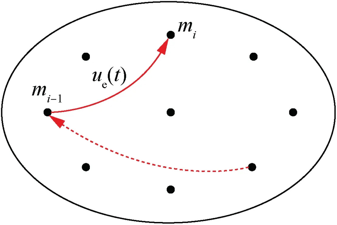
Fig. 2 Mode-set of the evader’s commanded acceleration.
where m(t) represents the discretized mode of the evader (see Fig. 2), and w(t) is the quantizing error regarded as a zeromean white and Gaussian noise with power spectral density sw.15For the methods of designing mode-set in the context of maneuvering target tracking, please refer to Refs.12,18-19.
Without loss of generality, the mode changes only once during the interception. Let tswdenote the mode switch time,and m1and m2denote the respective mode before and after the mode change, then m(t) is formulated as

where u(t) is the step function and satisfies

2.3. Observation model
To comply with Eq. (15), the observation model is given by


3. Maximal admissible mode decision delay
3.1. Structure of guidance system
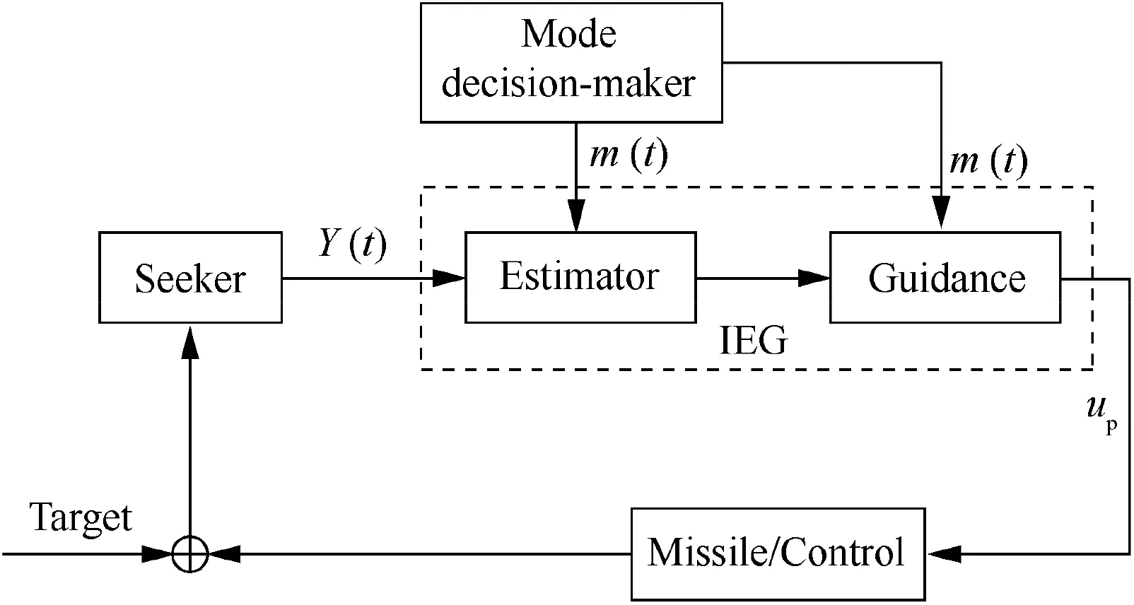
Fig. 3 A representative logic-based IEG frame.16
A representative frame of the logic-based IEG system is given in Fig. 3.16As depicted in this figure, the estimator and the controller are optimized separately; a mode decision-maker is introduced to output the evader’s acceleration command m(t)currently.Each value relates to a model;it brings flexibility to the system for several distinct models.Thus,a timely and precise mode decision-maker guides the estimator to select the true mode promptly and effectively. In addition, it guides the guidance processor to determine the appropriate guidance laws and parameters once the evader’s mode changes.Specifically,if m(t) is sufficiently small, the guidance law DGL/0 may be favorable because of the robustness and the efficiency; otherwise, DGL/1 is more applicable; Furthermore, if the sign of the acceleration command is distinguishable, it can be applied to shrink the acceleration reachable-set of the evader while computing ZEM.20Under such a configuration, we next derivate the error model of ZEM estimation and calculate MAMDD of the mode decision-maker.
3.2. Mean error of ZEM
Given that the true mode of the evader is identified by the mode decision-maker after a certain delay Δt,then the dynamics of the estimator is obtained as follows.


Introducing Eq. (10) into Eq. (4) yields

In the following derivations,assume that the final time satisfies condition:tf≥tsw+Δt.Then,three cases need to be considered separately.
Case 1.t ∈[0,tsw).The evader stays in the mode m1,namely the state equation satisfies

Assuming that the Kalman filter serves as the estimator,then the filter equation is given by

where k(t) stands for the continuous-time Kalman gain and satisfies

The prediction error covariance matrix P(t) obeys the following continuous time Riccati equation


Note that E{w(t)}=0 and E{v(t)}=0, then we get

where E{·}denotes the mathematical expectation.Due to Eqs.(22) and (23), the mean error of state, ζ(t), is given by

Case 2.t ∈[tsw,tsw+Δt).The evader’s mode is m2,then Eq.(16) becomes

The filter equation is also given by Eq.(18)because the pursuer still believes that the evader’s mode is m1,namely this period experiences a mode mismatch. It is easy to get

After some manipulations of Eq. (26), we can obtain

Inserting t=tswinto Eq. (22) yields

Due to Eqs. (27) and (28), we obtain

Therefore, ζ(t) satisfies

Case 3.t ∈[tsw+Δt,tf].The evader’s motion mode remains unchanged, so the state equation of the system is the same as Eq. (25). Notice that the estimator gets the true mode of the evader in this case, thus the form of the observer is given by

Thanks to Eqs. (25) and (31), x~(t) satisfies the following equation

Then, by solving Eq. (32) we get

Substituting t=tsw+Δt into Eq. (29) yields

Then, Eq. (33) reduces to

Therefore, ζ(t) satisfies

From Eqs.(30)and(36),it is found that the error of state is composed of two portions. The former part quantifies the effect of initial error, while the later quantifies the effect of mode mismatch.
The estimation error of ZEM measures the difference between the estimated ZEM and the true ZEM. By definition,

Then,the mean error of ZEM(denoted by η(t))is given by

Remark:due to Eqs.(9),(24),(30),(36)and(38),it is readily observable that the control input, up(t), does not occur in the right side of η(t), which suggests that the mean error of ZEM is independent of the adopted guidance law.
Without loss of generality, DGL/1 is used in the following sections.
3.3. Computation method for MAMDD
By virtue of the mode decision-delay, mode mismatch exists after the mode change, thus increasing the estimation error of ZEM.To ensure an ideal homing accuracy,a mode decision delay as small as possible is critical. Otherwise, the estimation results become too unreliable and the estimator may even diverge.In this paper,the capture zone boundary is interpreted as a coarse bound for calculating the acceptable mode decision delay.That is,if the decision delay is too great,the mean error of ZEM will exceed the boundary of the capture zone, as shown in Fig. 4. In this case, the delay is thought to be unacceptable for the guidance system.The boundary of the capture zone for DGL/1 is given by17

From the viewpoint of engineering heuristic, the boundary of the capture zone can be,at any time,interpreted as the guidance system’s maximal ZEM adjustment ability. More specifically, if the mode decision delay is small enough, the ZEM error remains in the capture zone during the whole interception. In this case, regardless of the control strategy adopted by the evader and the position of the true ZEM, it is possible to correct the miss caused by the inaccurate estimation by adjusting missile control within the time-to-go. In this way,the best performance of the interception(i.e.,the smallest possible miss distance) can be ensured. Oppositely, if the delay is too great, the ZEM error exceeds the capture zone boundary during the mode mismatch, namely the extent of miss is beyond the adjustment ability of missile control in such a limited time-to-go. Therefore, the mode decision delay is thought to be unacceptable for the guidance system. At this point, by limiting the mean error of ZEM to the boundary of capture zone, a naive constraint condition can be formulated as
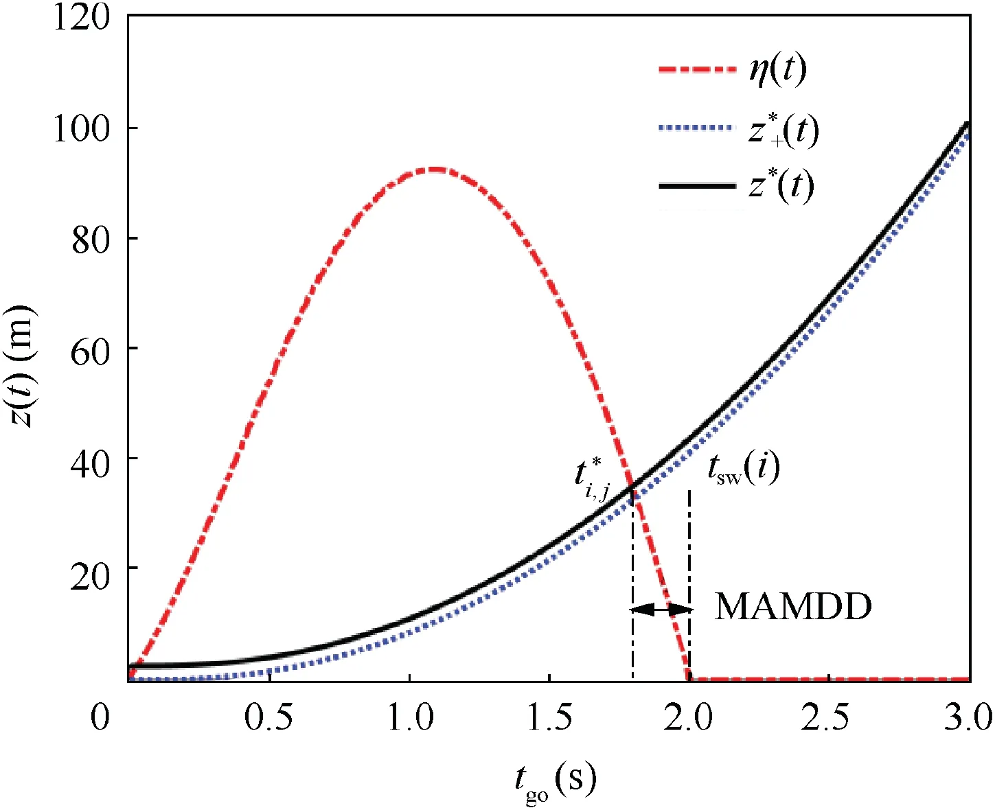
Fig. 4 Diagram of MAMDD.

Note that in a realistic interception problem the evader is not a mass point; it has a size. Thus, taking the evader’s size into account, Eq. (42) should be modified as

where L is the size of the evader. Therefore, as illustrated in Fig. 4, MAMDD can be defined as the difference between the intersection time of the two curves (z*(t) and |η(t)|) and the mode switch time, that is,

where t*satisfies the condition

Overall,the steps that are taken to obtain MAMDD can be summarized as follows:
4. Numerical simulation
In this section, simulations are performed to validate the proposed method via an interception instance of tactical ballistic missile.16The interception parameters are given in Table 2,and the estimator’s parameters are listed in Table 3.The gravity acceleration g equals to 9.8 m/s2.The accuracies of the seeker for angular and pursuer’s acceleration are settled by 5 mrad and 1m/s2. A bang-bang strategy is used for the evader,that is, it keeps the maximum acceleration when interception begins and remains at the maximum acceleration in the opposite direction after mode switching.
The time responses of MAMDD for different mode switch time and different levels of maneuvers(Δm=5g, 10g, 15g, 20, 30g)are given in Fig.5.In these simulations,to isolate the effect of the initial error,the initial state of estimator is assumed to be precise, that is x~0=0. It can be seen in Fig. 6 that the values of MAMDD vary significantly with respect to the mode switch time. Specifically, when the switch time is earlier than tgo=0.2 s,MAMDD is nearly proportional to the mode switch time. A larger MAMDD is acquired in the case of an earlier mode switch (corresponding to a greater tgo). Because a larger z*(t) is allowed at an earlier time of the interception, as shown in Fig. 5, and the response speed to target maneuver is settled for the estimator with a constant bandwidth.Therefore,a larger MAMDD is obtained according to Eq. (44), namely the requirement to identify the evader’s motion mode is less rigorous for the mode decisionmaker. It is shown that if the mode change happens when tgois smaller than 0.2 s, MAMDD increases first and becomes infinite (i.e. without constraint on mode decision-maker) at a certain small tgo. The reason is that the curve of z*(t) keeps almost unchanged during this period and tgois so small that the error of ZEM will not exceed z*(t)in the remainder of such an extremely short time. It implies that, for this case the process of mode decision has almost no effect on the performance of the final interception and the maneuvering case can be deemed as a non-maneuvering one. For the five maneuver levels above, it is readily concluded that the larger the magnitude of mode change,the smaller the acceptable MAMDD.In other words, stricter requirements are imposed on the mode decision-maker to intercept a highly maneuvering target than to intercept a weak one.
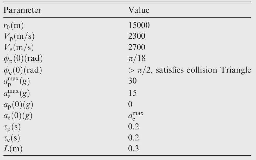
Table 2 Interception parameters.
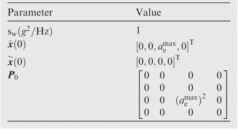
Table 3 Estimator’s parameters.
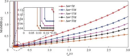
Fig. 5 MAMDD with switch time under different Δm.
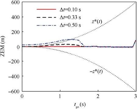
Fig. 6 ZEM with different mode decision delays when mode switch occurs at tgo =2.0 s.
Fig.6 gives the ZEM with respect to the time-to-go for different mode decision delays. The mode switch happens at tgo=2.0 s, and the mode change value Δm=30 g. It can be obtained from Fig. 5 that MAMDD ≈0.33 s in this case.The mode decision delays are set to be Δt=0.1 s,Δt=0.33 s and Δt=0.5 s respectively. As shown in this figure, if the mode decision delay is not greater than MAMDD(that is, the red and black dashed line), the ZEM remains in the boundary of the capture zone at the final time,as the error caused by mode mismatch can be adjusted by the missile control within the time-to-go.However,if the mode decision delay is greater than MAMDD(the blue dash-dotted line),the ZEM is outside the boundary of the capture zone when the engagement ends.Since the error is too large and cannot be corrected,the inaccurate ZEM estimate misguides the interceptor and further degrades the interception performance.
Define

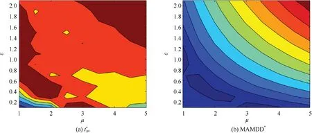
Fig. 7 Diagram of and MAMDD*.
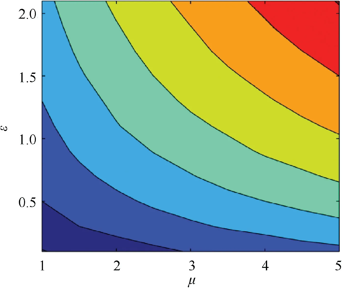
Fig. 8 under different μ and ε.
where MAMDD*anddenote the minimum MAMDD and its corresponding switch time, respectively anddenotes the mode switch time when MAMDD first turns to infinity.
Fig. 7 presents MAMDD*andunder different μ and ε.MAMDD*represents the most promising value for the mode decision-maker in identifying the evader’s mode. That is, if the delay is lower than MAMDD*,the estimation performance can always be guaranteed whenever the evader’s maneuver occurs during the whole interception. In these simulations,the parameters of the pursuer are set to be constant withg and τp=0.2 s. μ is set between (1,5) with step of 0.5; ε is set between [0.2, 2] with interval of 0.2; the bangbang control strategy is assumed to be used by the evader.As shown in Figs.7(a)and 7(b),when μ is settled,increases approximately with the increase of ε, which leads to a larger MAMDD*. Thus, a less rigorous requirement can be put on the decision-maker for intercepting the evader with the same maneuverability but a larger time constant. Meanwhile, when ε is constant,increases approximately with the increase of μ,which results in a larger MAMDD*.Thus,we can reach to the conclusion that, for evaders with the same time constants, if the evader holds a higher maneuverability, a more rigorous request is exerted on the mode decision-maker to discriminate its motion mode.
Fig. 8 gives the results ofunder different μ and ε.is the moment indicating that there is no requirement for the mode decision-maker.That is,if the switch time is smaller than, the maneuver of the evader becomes meaningless and has no effect on the admissible mode decision delay. Therefore,it can be treated as a non-maneuvering case.This is consistent with the findings reported in the previous work of Shinar et al.11from a different point of view (when the mode switch time is close to the final time, the average miss distance approaches zero).As shown in Fig.8,is approximately proportional to μ and ε.Therefore,we can draw a conclusion similar to that we drew from Fig. 7, a stricter requirement should be put on the process of mode identification when intercepting an evader with a higher maneuverability and a smaller time constant.
In practice,one can use the proposed computing method of MAMDD to make requests to the mode decision-maker in order to guarantee a required interception performance.
5. Conclusions
In present work,a method for calculating the MAMDD of the mode decision-maker is proposed by limiting the ZEM error.It is concluded that the MAMDD decreases when the mode switch time is increased for earlier maneuvers.However,when the mode switch time is close to the final time, the MAMDD increases first and then turns to infinity. Furthermore, for different levels of maneuver, the larger the mode change value,the greater the MAMDD. The proposed method for calculating MAMDD serves as a guideline in designing the mode decision-maker and in evaluating the performance of an Integrated Estimation and Guidance system.
杂志排行
CHINESE JOURNAL OF AERONAUTICS的其它文章
- Special Column of BWB Civil Aircraft Technology
- Assessment on critical technologies for conceptual design of blended-wing-body civil aircraft
- Exploration and implementation of commonality valuation method in commercial aircraft family design
- Effects of stability margin and thrust specific fuel consumption constrains on multi-disciplinary optimization for blended-wing-body design
- Nacelle-airframe integration design method for blended-wing-body transport with podded engines
- On developing data-driven turbulence model for DG solution of RANS
