Design and feedforward control of large-rotation two-axis scan mirror assembly with MEMS sensor integration
2019-09-28HaiHUANGXintaoZHENGWeipengLI
Hai HUANG, Xintao ZHENG, Weipeng LI
School of Astronautics, Beihang University, Beijing 100083, China
KEYWORDS
Abstract As a key component of electro-optical systems, a Two-axis Scan mirror AssemblY(TSAY)is usually used for Line-of-Sight(LOS)precision pointing,tracking,scanning,and stabilizing. Therefore, it is necessary for a TSAY to have a large angular range, high dynamic characteristics, and small mirror surface distortion. Furthermore, vibration from carriers of electro-optical systems,such as spacecraft and airplanes,is inevitable,so it is critical to guarantee the control accuracy of a TSAY under vibration. In this paper, a TSAY prototype is designed and developed. To increase the control bandwidth,structural topology optimization is applied to the TSAY’s elliptical mirror to reduce the moment of inertia, meanwhile keeping surface flatness. A flexible hinge is adopted to achieve a large angular range.To suppress the angular perturbation caused by the base linear vibration,an adaptive feedforward loop with base-integrated Micro-Electro-Mechanical System (MEMS) accelerators is constructed to enhance the TSAY’s feedback loop. Simulation and experimental results show that the TSAY prototype’s two-axis mechanical angular ranges are more than ±3.2°, the mirror surface flatness Root Mean Square (RMS) value is better than 0.04λ, and the closed-loop bandwidth is beyond 330 Hz.These are suitable for most applications.Besides,the angular perturbation caused by the base vibration can be suppressed more than 37.7% with the addition of the adaptive feedforward loop.
1. Introduction
A Two-axis Scan mirror AssemblY (TSAY) is an optical device for beam steering, which plays an important role in free-space optical communications, imaging system stabilizations, adaptive optics, optical tracking and laser scanning systems,etc.1For airborne surveillance and reconnaissance,Lineof-Sight (LOS) must be scanned to reduce the scene drift caused by the relative motion between a sensor and a target,2so the large rotational capability of a TSAY is required for back scan. A wide control bandwidth is a TSAY’s another key property for optical jitter control of an airborne laser3and a spaceborne infrared detector,4as well as a fast beam scan of high-resolution laser radar images.5A TSAY should also have high surface quality, because it is essential in applications of coherent optical communication,6coherent combining of high-energy laser,7etc.
A TSAY’s control bandwidth can be increased effectively by reducing the moment of inertia of its moving parts(including the mirror,the frame,the motor mover,and hinges).Since TSAYs are always used in reflective optical systems,the shapes of the spots projected on the mirrors are elliptical. Therefore,elliptical mirrors are suitable for these applications.Compared with a circular mirror, an elliptical mirror can reduce a TSAY’s moment of inertia as well as its volume, but the moment of inertia about the elliptical mirror’s major/minor axis should be the same to simplify the controller design. Furthermore, a decrease in the moment of inertia of the moving parts, especially mirrors, probably weakens the stiffness of the mirrors,which affects the surface quality.Lightweight mirrors with advanced structures,such as foam-cell structures,can achieve high stiffness-to-weight ratios,8but the manufacturing process is complex and costs are high. To solve the problem,optimization design of a mirror with common optical materials is adopted. Sizing optimization can be used for lightweight mirrors with pocket patterns on their substrate, achieving the minimum of mass/inertia with the required optical performance.9However, the artificial-setting pocket geometry of the substrate limits the final solution.A topology optimization method can overcome the initial geometry limitation. The design domain can be the whole substrate, the objective and constraint functions can be the surface error, acceleration values, moment of inertia, weight, primary frequency, etc., and the loading cases are self-weight loading, random vibration,polishing pressure, etc.10-12
A TSAY’s high rotational capability can be realized by using Voice Coil Motors (VCMs) as actuators and flexible hinges as joints, which are adopted in a majority of scan mirrors.2,13,14Although piezoelectric actuators, the counterparts,achieve superior resolution and fast settling time,15VCMs have longer strokes and better suitability in shock and vibration, while their response, output force, and resolution are fairly good for most applications.Flexible hinges are designed and assembled to guarantee the transmission resolution and accuracy as well as large rotation, because they eliminate mechanical friction and non-linearity such as backlash, hysteresis, static resistance, etc.16,17In addition, a flexible hinge has the advantages of lubrication free,wide operating temperature range, and higher reliability than that of a traditional bearing.18A flexible hinge should approximate a bearing connected with the mirror, to ensure higher axial/torsional stiffness and lower rotational stiffness. However, flexible hinges’stiffness in different directions is coupled, which means that axial/torsional stiffness cannot be far higher than rotational stiffness. In addition, reducing the rotational stiffness to enlarge the angular range will inevitably reduce the axial/torsional stiffness.19
In practical applications, TSAYs are always onboard airplanes or vehicles, which suffers from severe shock and vibration.Meanwhile,due to manufacturing and assembling errors,a TSAY’s rotational axis(or Mechanical Axis(MA))and Inertia Axis(IA)cannot coincide strictly.Thus,the mirror’s angular vibration will be excited, which severely weakens the LOS accuracy and stability. Furthermore, the coupling of flexible hinges makes vibration more serious.For the mirror’s angular vibration that is caused by the base’s angular vibration,a feedforward loop can be built to suppress such vibrations. Lee et al.20studied the spacecraft angular displacement’s measurement and estimation for a high-frequency feedforward loop,to increase the low-frequency loop through optical tracking. To reject aircraft disturbances with the feedforward approach,Gutierrez et al.2adopted two kinds of complementary inertial sensors for angular vibration measurement, and blended their data to produce an effective response to setup a feedforward loop.Watkins et al.21and Glaese et al.3measured beam angular vibration instead of base angular vibration for feedforward control. Another control structure is ‘‘stable platform method”22,23in which inertial angular sensors are fixed on a moving part (platform) to measure angular vibration, so that all controls are implemented in a closed loop,and NO feedforward gain matching is needed to achieve high precision and stability. However, the size of the platform would be bigger for fixing inertial sensors. For controller design, an adaptive algorithm is usually adopted by many of the aforementioned studies to suppress outside disturbances.Meanwhile,the base’s linear vibration can also excite angular vibration which should be concerned with a similar method.
Onboard linear vibration should be measured for feedforward loops to suppress a mirror’s angular vibration. Platform vibration has been previously measured by gyros, angle sensors,angular rate sensors,geophone sensors,etc.To get better vibration suppression capability, faster measuring equipment such as accelerometers should be employed to increase the loop rate. Conventional linear accelerometers, such as quartz accelerometers,20,24have relatively large volume and heavy weight.They are difficult to be integrated into components like TSAYs, to realize miniaturizations from practical demands.Due to the smaller volume and weight,lower power and price,and increased accuracy and bandwidth, MEMS sensors are gradually applied to precise LOS controls,25-27and they are suitable for a TSAY’s base linear vibration measurement.
Previous work has shown that TSAYs with large rotational capability, wide bandwidth, high surface accuracy, and fine LOS accuracy/stability during harsh environment are valuable.However, few studies have focused on the design of TSAYs with aforementioned features as well as experimental verification.In this paper,a large-rotation TSAY with base-integrated MEMS accelerometers was studied (see Fig. 1). In addition to the TSAY’s system design and experiments,this paper reports on (A) layout design of motor movers, a flexible hinge, and sensor probes on the TSAY’s mirror back to realize two-axis large rotation, (B) minimization of the elliptical mirror’s moment of inertia, as well as equality design of the moment of inertia of the major/minor axis, with a topologic optimization method,and(C)feedforward control with base-integrated MEMS accelerometers(abbr.MEMS)to increase the TSAY’s performance in harsh environment.
This paper begins with a discussion of the TSAY’s characteristics and a summary of their design and control approaches that have been used or studied.After overviewing the TSAY’s key components and layouts, the mirror’s topology optimization and verification and the flexible Hooke joint’s design and analysis are studied in Sections 3 and 4,respectively.Then,dynamic modeling when considering the deviation between MA and IA, and control system design which consists of a PID feedback loop augmented by an adaptive feedforward loop are described in Sections 5 and 6, respectively. Finally,A TSAY prototype’s experimental setup with base-integrated MEMSs is conducted, and experimental results are shown in Section 7, including system identification, angular range,dynamic response, and feedforward control performance.
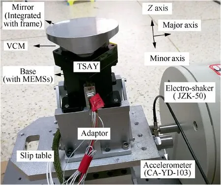
Fig. 1 Photo of TSAY and experimental system.
2. System overview

Fig. 2 Schematic diagram of TSAY.
As shown in Figs.1 and 2,the TSAY is composed of a mirror,a base,VCMs,MEMSs,a flexible hinge,and sensors.The mirror should have high stiffness and low moment of inertia,usually glued or bolt-jointed on a frame.Furthermore,the mirror needs to maintain sufficient surface quality, while the frame needs to be connected to the other parts and bear the loads.Commonly, the mirror and the frame are separately designed with different materials. Due to the different thermal expansion parameters,there probably exists high thermal stress that distorts the mirror surface.28An integrated design and manufacture of the mirror and the frame avoid the stress and deformation in an assembly process,and high surface quality will be obtained. In addition, stress between the hinge and the mirror should be carefully considered.As a driving torque is transmitted to the mirror directly, an appropriate bearing structure is necessary to ensure the accuracy of the mirror surface. In this paper, an integrated method is adopted to design the mirror,and topology optimization is applied to get the structure of reinforce ribs,which distribute the driving torque to the mirror and ensure the accuracy of the mirror surface.
Usually,an elliptical mirror’s moments of inertia along different axes are different, which will produce a torque perpendicular to the mirror when its rotational axis is not the major/minor axis.This torque will weaken the TSAY’s control accuracy and reduce hinges’ service time. To solve the problem, the mirror’s thickness along the major axis is designed as unequal.
VCMs, probes of eddy current sensors, and cross-spring flexural pivots19(CSFPs, adopted as flexible hinges) are located below the back of the mirror.VCMs’movers are fixed on the mirror directly, and probes keep a distance from the mirror. Fig. 3(a) shows the layout design in this paper. For comparison, a usual layout design2is shown in Fig. 3(b). As shown in Fig. 3(a), the sensor field, of which the diameter is at least three times that of the probe, makes use of the weight-reducing holes of the mirror, and the CSFP is fixed on the VCM instead of on the mirror. The predominant advantage of this layout is that the axial distance is compressed(dv <Dv,dp <Dp),so the angular range is increased with the remaining VCM stroke and sensor range. Other advantages include that the moment of the moving part is decreased and the CSFP’s stress imposed on the mirror is reduced.
Four MEMSs(two per axis,as shown in Fig.2)are fixed on the base of the TSAY to measure the base’s linear vibration and avoid the effect of the base’s angular vibration. The measurement accuracy will be increased when increasing the baseline of the two sensors,but that will enlarge the volume of the TSAY’s base and stiffness will be weakened. Therefore, the compromise is adopted.
3. Mirror optimization and verification
3.1. Mirror optimization
3.1.1. Optimization model

Fig. 3 Layout design in this paper and usual layout design.
Density-based methods are widely used methodologies for topology optimization of continuum structures, which include the most popular method Solid Isotropic Material with Penalization(SIMP).Based on the concept of the SIMP method,the density of each element is used as a topology design variable,and the optimization problem can be formulated as follows:

where n is the total number of elements in the ground structure, and m denotes the number of constraints; xiand f(xi)are the intermediate density and the ith element moment of inertia about the minor axis, respectively; gj(X) represents the jth constraint; xb(=0.001) is the lower bound of xiand set as a small value which is used to avoid singularity.To achieve a 0/1 density distribution, the following power law penalization is used for the density approach:

where Eidenotes the penalized elastic modulus of the ith element, and E0denotes the none-penalized elastic modulus.Parameter α is the penalization factor, which typically takes a value between 2 and 4. Load conditions and constraints can be found in Section 3.2.1.
Fig. 4 shows a prototype of the moving part, in which the four lines are simplified CSFPs. The optimization model can be divided into a design domain and a non-design domain.Screws and other accessories in the actual model, as well as the magnet at the major axis,are non-design parts,which have been removed. As the magnets (VCMs’ movers) at the minor axis are connected with CSFPs, they are reserved and simplified.When calculating the inertia moment of the moving part,the removed parts are also taken in consideration.The dimensions of the elliptical mirror are 79 mm×60 mm. The moving part’s substrate and magnet are manufactured with aluminum alloy and magnetic steel,respectively,and their elastic moduli,Poisson’s ratios and densities are 69 GPa and 120 GPa, 0.33 and 0.29, and 2700 kg/m3and 7900 kg/m3, respectively.
The rectangular coordinate system is defined as follows:major axis—minor axis—Z axis(see Fig.4).The Z axis is perpendicular to the mirror, the origin is at the center of the mirror surface,and the directions of the major and minor axes are established according to those of the ellipse.

Fig. 4 Prototype of moving part.
According to the distribution of the mirror substrates stress, the relative density distributions of different parts are different in the optimized result, and the relative density reflects the importance of each part. The less important parts of the optimization area are removed,and the important parts are retained.
The finite element model of the simplified moving part is shown in Fig. 5. CSFPs are constructed using Bush elements,and the outside endpoints of the two Bush elements at the major axis are fixed. MPC-Bar2 elements are used as the connections among Bush elements as well as those between Bush elements and magnets. The parameters of the Bush elements are shown in Table 1. To be consistent with manufacturing processes of CNC (Computerized Numerical Control) milling to remove structural materials, Hexahedron elements are used to build other structural parts.
3.1.2. Load conditions and constraints
The mirror’s main loads are the motors’driving forces,and the structural response is the corresponding pure distortions.Optimization constraints are as follows:
(1) The PV value of the surface error should be less than 600 nm, and with the loads, ‘‘push-and-pull” forces are±2.2 N on both the major and minor axes.
(2) The ratio of the moment of inertia about the mirror’s minor and major axes should be between 0.9 and 1,and this mathematical constraint expression can be formulated as follows:

where Iminorand Imajorare the moments of inertia of the moving part at the minor and major axes, respectively. The constants in the parentheses represent the moments of inertia of the removed parts, and the units are kg·m2.
(3) The optimal shape of the moving part should be symmetrical with respect to the Major Z plane and the Minor Z plane.
(4) Considering the manufacture processes of CNC milling,the direction to remove materials should be perpendicular to the mirror surface.

Fig. 5 FE model of prototype.
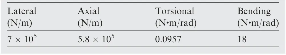
Table 1 Stiffness of Bush elements.

Table 2 Coordinates of nodes on mirror surface.
To simplify the calculation of the surface error’s PV value in Constraint (1), 16 nodes on the mirror surface are selected as verification samples, as shown in Table 2. If the nodes’ displacements satisfy the constraint, the whole mirror is considered to satisfy the constraint. The displacements of the mirror’s FE analysis are composed by (A)the pure distortion,and (B) the deformation of the support structure such as CSFPs. To get the exact PV value, the Z axis displacements caused by the pure distortion should be made clear.Therefore,the 16 nodes’Z direction displacements are calculated with the mirror’s rigid model firstly, and then subtracted from the Z direction displacements of the FE model.
3.1.3. Optimization result
Optimization is conducted by Hyperworks software.29Fig. 6 shows the topology-optimization output density contour with a relative density setting of 0.55. In the figure, the red areas represent the most important FE meshes (relative density is Constrain(1)),while the blue and green areas represent the less important FE meshes. The termination criterion is the differences of Iminorand Imajorbetween two iterations smaller than 5×10⁻⁶kg m2as well as Constraints (1) and (2) being satisfied.The optimization process experiences 53 iterations totally.Fig.7 shows the two axes’moments of inertia during iteration,and they are close to each other firstly and then separate slightly in order to satisfy the constraints. Fig. 6 also shows that the value of Iminor/Imajorbegins at 0.82 and ends at 0.95,which means that the inertia moments of the major and minor axes are approached after the optimization.
3.1.4. Mechanical design

Fig. 6 Topology-optimization output density cloud.
The topology-optimization result is reconstructed to a mechanical model, as shown in Fig. 8. Based on the model shown in Fig. 6, ten holes are manually distributed on the frame and designed as fan-shaped sections with similar areas,and the thickness of the ribs between the holes are 2 mm.The frame’s thickness and width in the middle are 16 mm and 15.5 mm, respectively, the length of the slope is 14 mm,and the frame’s thickness at both ends is 4 mm. When the moving part is assembled with motors and accessories, the moments of inertia about the minor and major axes are 4.12×10⁻⁵kg·m2and 4.44×10⁻⁵kg·m2(Iminor/Imajor=0.928), respectively, the weight is 149 g, and the theoretical distance (that is d in Fig. 2) between MA and IA is 1.5 mm.

Fig. 7 Moments of inertia during optimization.

Fig. 8 3D mechanical model of optimized mirror.
3.2. Pure distortion verification
3.2.1. Zernike polynomials
Under the effects of the motors’ active force, the CSFP’s constraint force, and the gravity, the moving part will generate rigid body displacement and flexible deformation. The flexible deformation that affects the quality of the optical system is called pure distortion.Zernike polynomials are used to analyze the pure distortion of the moving part to verify the mirror’s surface accuracy. The first 15 items of Zernike polynomials are selected according to Ref.30. Items 1-3 which represent the Z axis translation and major/minor axis rotations are not considered during the calculation.Items 4-15 are taken to represent the pure distortion.The coefficients of the items are constructed by the coordinates of the mirror surface nodes which are obtained from the finite element analysis.
3.2.2. Pure distortion analysis
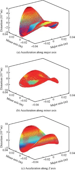
Fig. 9 Pure distortion of mirror surface.
To simulate the loadings, ±2.2 N ‘‘push-and-pull” forces are applied on both the major and minor axes, and 5.5g acceleration is simultaneously applied on the mirror along the major/minor/Z axes, respectively. Fig. 9 and Table 3 show the pure distortions of the mirror surface and the corresponding PV value and RMS value, respectively, when acceleration is applied on three axes. In Fig. 9, the points are the FE nodes on the mirror surface, and the surface is the fitted mirror surface by Zernike polynomials. Results show that the PV value and RMS value of the mirror surface are less than 0.18λ and 0.04λ, respectively, where λ=632.8 nm.

Table 3 Pure distortion of mirror surface.
4. Flexible Hooke joint design and analysis
4.1. CSFP
A CSFP is a cylindrical-shaped and limited-rotation bearing with predictable and repeatable performance applicable to a TSAY. A CSFP consists of two stainless steel sleeves supported by three flat, crossed springs.19Based on the requirement of large rotation, the limitation of installation space,and the mass/inertia property of the moving part, a C-flex bearing A-30 is adopted in this paper, and the stiffness is tabulated in Table 1.
4.2. Flexural Hooke joint
To realize two-axis scan capability,four CSFPs are assembled as a Flexural Hooke Joint (FHJ) by a shafting. The FHJ’s structural characteristics should satisfy the following criteria:(A) a lower rotational stiffness to decrease the corner frequency of the TSAY’s two LOS DOFs,(B)a higher axial,lateral,and torsional stiffness with and without CSFP rotation to restrict the piston,shear,and twist of the moving part,and(C)a high local mode frequency of the shafting to limit the jitter.
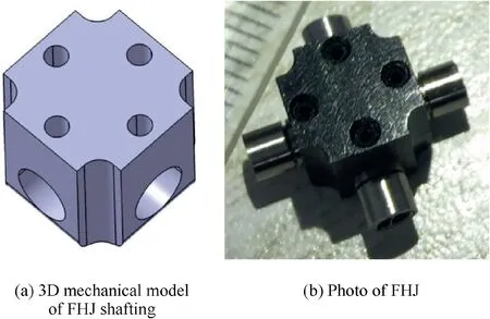
Fig. 10 3D mechanical model of FHJ shafting and photo of FHJ.
The sleeves of a CSFP are smooth which can be installed by simple methods as set or clamp screws. Fig. 10 shows the mechanical model of the FHJ shafting designed in this paper.Four holds on the sides are used to contain the sleeves, and their axes should be strictly orthogonal and coplanar to restrict coupling,with four thread holds on the top for set screws.The shafting is chamfering to prevent interference during large rotation and stress concentration, meanwhile decreasing the shafting’s weight to increase its local mode frequency. Fig. 10 shows a photo of the FHJ.
4.3. Analysis
Fig.11 shows the FE model of the FHJ with moving parts,and Table 4 shows the computed mode shapes and frequencies.The values show that (A) the rotational stiffness (around the major and minor axes) is low, and the variation in the rotational stiffness, when rotated 3°, is very small (within 1.5%);(B) the lateral stiffness (along the major and minor axes) is high, and the variation in the lateral stiffness, when rotated 3°, is very small (within 1.5%); (C) the torsional stiffness(around Z axis)is high,and the variation in the torsional stiffness,when rotated 3°,is relatively small(within 5%).Furthermore, the moving part and the FHJ’s first-order local modal frequencies are 5576 Hz and 9442 Hz, respectively, which are far higher than the control bandwidth.
5. Dynamic modeling of TSAY
Due to errors from manufacture and assembly, a consistency of the TSAY’s IA and the FHJ’s MA cannot be strictly guaranteed. Therefore, the mechanism dynamics behave like a rocking problem that couples secondary modes into rotation.31The key elements of such a problem are shown in Fig. 2. The rotation inertia of moving parts relative to the MA(Jm)is formulated as

where Jp, m, and d represent the rotational inertia relative to the IA,the mass of moving parts,and the distance to the FHJ’s MA, respectively.
The TSAY’s base vibration results in a disturbing torque on the moving parts. If the MA coincides with the IA, the moment of inertia is the smallest, which means that the dynamic performance is the best. The disturbance torque caused by the base’s angular vibration is proportional to the angular acceleration, while the disturbance torque caused by the base’s linear vibration is proportional to the product of the linear acceleration and d.
The angular acceleration and linear acceleration at the MA,which are caused by the base vibration, are represented as β and b, respectively. β’s equivalent disturbing torque M1is

The linear acceleration at the centroid of the moving part b1is

where F represents the linear force on the MA. The angular acceleration at the centroid of the moving part β1is

Meanwhile,the relation between b1and β1can be written as

Solving Eqs. (5)-(7) can get β1, and β1’s equivalent disturbing torque M2is
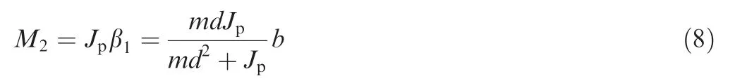
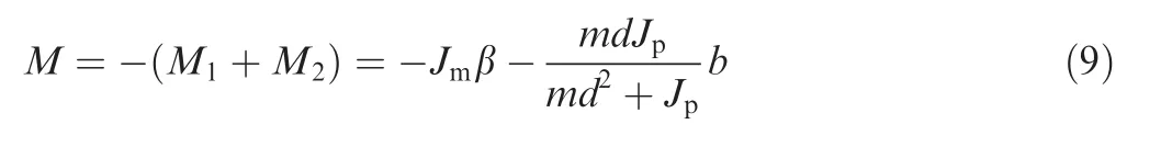
To suppress the base vibration, the control torque M should be
To obtain β and b, two MEMSs (see Section 7.1) are fixed on the base, and their sensing axes are parallel to the majoraxis/minor-axis plate to measure the linear accelerations in the horizontal direction, as shown in Fig. 2. Therefore, b and β are
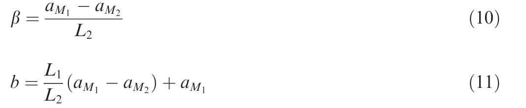
where aM1and aM2are the outputs of MEMSs, while L1and L2are the distance between the MA and the top MEMS and the distance between two MEMSs, respectively, as shown in Fig. 2.
Substituting Eq. (10) and Eqs. (11) to (9), we can get M as

where
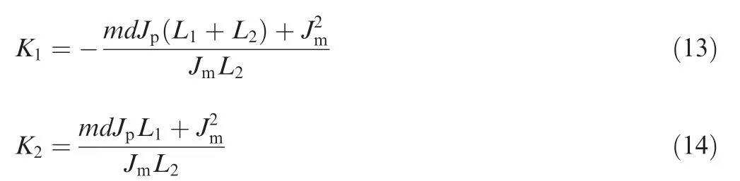
The control torque M is a linear combination of the two MEMS. For Eqs. (13) and (14), the parameters’ uncertainty and errors are inevitable, so an adaptive control method is adopted to online adjust K1and K2.
After the mechanical design of the TSAY, the aforementioned structural parameters can be obtained as follows:m=0.147 kg, Jp=4.12×10⁻⁵kg·m2, Jm=4.15×10⁻⁵kg·m2, L1=0.0439 m, L2=0.0168 m, and d=0.0015 m.
6. Controller design
The controller of the TSAY is composed of a PID feedback loop of the LOS error (with an eddy current sensor) and an adaptive feedforward loop of an accelerometer measurement(with MEMSs). With the feedback loop only, vibration suppression can be achieved in a lower frequency band due to the inevitable phase delay caused by sensor noise,signal transmission delay,sampling rate limitation,and hardware computing limitations. Although the suppression capability can be improved by increasing the feedback gain, it will reduce the stability margin of the system, and in severe cases, it will directly lead to system failure. On the contrary, the feedforward loop does not directly use the angle output signal, but uses an additional sensor to measure the base disturbance to avoid instability,then calculates the force required to suppress the disturbance according to a pre-identified system model,and realizes a non-delayed disturbance suppression. However,it is greatly affected by the accuracy of the pre-identified model. Therefore, an inner PID loop is adopted to constrain the actual system to be a more exact model to reduce the compensation error.
Because the structural characteristics of two axes are similar, the controller can be decoupled as two SISO systems. A block diagram of the controller for one axis is shown in Fig. 12.
6.1. PID controller
A PID controller is designed to build the feedback loop with an eddy current sensor, as shown in Fig. 12. In this paper,the key of the TSAY’s controller design is to demonstrate that the mirror’s angular vibration can be suppressed by an adaptive feedforward loop.Therefore,the feedback loop is not built with a high-performance robust controller as used in Ref.32.
The iterative feedback tuning method is applied to tune PID parameters. This method is a model-free technique for optimization of the parameters of a controller of a fixed structure using only signal information on a closed-loop system.33Its advantages include achieving the minimum settling time with no or minimal overshoot. Then, the PID parameters of the major and minor axes are as follows: PMaj=4.1,IMaj=15.4, DMaj=0.025, PMin=4.0, IMin=16.8, and DMin=0.022.
6.2. Adaptive feedforward loop
An LMS adaptive controller with a reduced number of operations34is adopted to set up the feedforward loop with MEMSs,as shown in Fig. 11. The output of the adaptive loop u(n) is

where aM(n)is the observed disturbance by MEMSs at time n, and K(n) is the adaptive filter weight vector at time n.
Here,μ is a parameter that controls the convergence stability and rate. The reference model Gr(s)is composed of closedloop parts such as VCMs, FHJs, eddy current sensors, and PID, but does not include the disturbance, which means that the output of G(s) is the desired angle of the TSAY. e(n) is the error between the desired and actual angles of the TSAY at time n.
In this paper,the initial adaptive filter weight vector K(0)is set as [-0.0033,0.0030]Taccording to Eq. (13), Eq. (14), and structural parameters. μ is set as 0.00006.
7. Experimental verification
7.1. MEMS module
Two MPU-6050 modules (see Fig. 13)35are adopted in this paper. Each module has a digital-output accelerometer with a programmable full-scale range up to ±16g, and the cutoff frequency(low-pass filter response)is set as 260 Hz.The module’s volume is 15.3 mm×15.3 mm×2 mm,and the weight is 0.7 g.

Fig. 12 Block diagram of controller.

Fig. 13 Photo of MPU-6050 module.
7.2. Experimental setup
The experimental setup is shown in Fig.1.A TSAY prototype is fixed on a slip table with an adaptor, and excited by an electro-shaker (Sinocera Inc., model: JZK-50) to simulate the base’s linear vibration. The VCMs (BEI Kimco, model:LA08) and eddy current sensors (MICRO-EPSILON, model:eddyNCDT 3010) inside the TSAY prototype are shelf products. The controller hardware is self-designed and composed of a DSP (TI, model: TMS320C6713), 16 bit AD/DA, and an analog power amplifier.
7.3. Results
7.3.1. System identification Firstly,system identification is carried out with the experimental system to get an open-loop model of the TSAY prototype.This model is used to build the reference model Gr(s) for the adaptive feedforward loop, as well as the simulation models Gvcm(s) and Gmp(s), as shown in Fig. 12.
The TSYA with a flexible hinge is a typical ‘‘mass-spring”second-order system.36Due to the first-order inertia characteristic of the electric system, the whole system is a three-order system as

where k is the scale factor that represents the relation between the gain of the control system and the actual rotation angle,m is the time constant, ωnis the natural frequency, and ξ is the damping ratio.
A white Gaussian noise is assigned to the TSAY prototype,and the major-axis and minor-axis open-loop output angle of eddy current sensors is then obtained using signal processing.Fig.14 shows the open-loop frequency response,and the transfer functions are

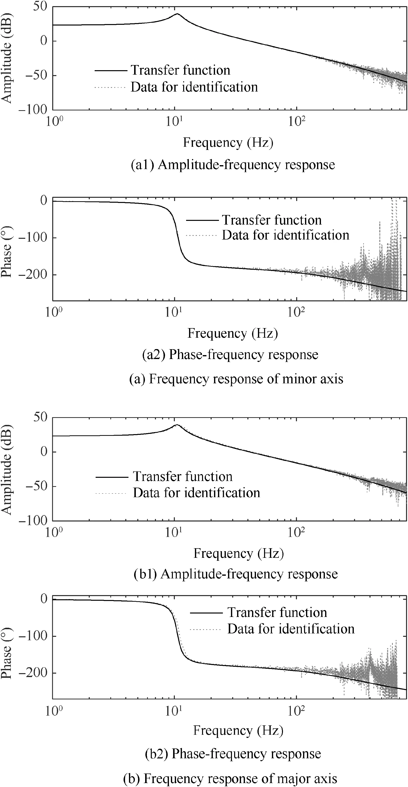
Fig. 14 System identification results.
The results show that the frequencies around the major/minor axes are 10.5/11.0 Hz, respectively, which coincide with the value of FE analysis (shown in Table 4).
7.3.2. Angular range and closed-loop bandwidth

Table 4 Computed mode shapes and frequencies of FHJ &moving part.
To exam the TSAY’s mechanical angular range,a circular trajectory is drawn under a dual-axis operation as shown in Fig. 15, and the angular ranges of both axes are higher than±3.2°.To test the dynamic behavior of the TSAY,the closedloop bandwidth is tested, and the Bode diagram is shown in Fig. 16. The result shows that the small angle (0.057°)closed-loop -3 dB bandwidths of the major and minor axes are 345 Hz and 336 Hz, respectively.

Fig. 15 Mechanical angular range.
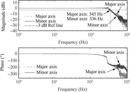
Fig. 16 Closed-loop Bode diagram.
Compared with similar assemblies, such as TAFA FSM37and FSM M-3G2of which the angular ranges/closed-loop bandwidths are ±0.57°/280 Hz and ±1°/250 Hz, the TSAY’s superior performances are experimentally verified.
7.3.3. Adaptive feedforward control performance
To verify the angular vibration suppression capability under the base’s linear vibration, a sinusoidal acceleration with amplitude of 15 m/s2and frequency of 8 Hz is produced by the electro-shaker.The control target is to keep the TSAY prototype at ZERO. Fig. 17 shows the experimental amplitude measured by the eddy current sensor with and without using adaptive feedforward control.Before 0.35 s,only the PID controller is active, and the amplitude of control error is 0.0175°.After that,the adaptive feedforward controller is added,so the amplitude of control error converges to 0.0109°, decreased by 37.7%, and the effect is stable. Further study shows that increasing the loop rate and decreasing the MEMS’s delay will improve the suppression effect. That means, a better system performance will be obtained when the hardware performance is improved.
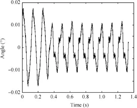
Fig. 17 Experimental amplitude with and without adaptive feedforward control.
8. Conclusions
In this paper, a TSAY is proposed to realize a two-axis large angular range,a high bandwidth,and a high surface accuracy.Layout design of the key parts is applied to realize compactness and high efficiency. Structure and dynamic models of the moving part,as well as the control system,are established.Topology optimization of the mirror and the feedforward loop with base-integrated MEMSs is carried out to increase the bandwidth and surface accuracy simultaneously. An FJM is designed and analyzed for large rotation capability. A TSAY prototype is manufactured, and an experimental system is set up. Numerical and experimental results show that:
(1) The mirror’s moment of inertia is optimized, and excellent PV/RMS values of the mirror surface are obtained.
(2) Mechanical angular ranges are more than ±3.2°, and the closed-loop bandwidth is beyond 330 Hz.
(3) Adaptive feedforward control with MEMSs can suppress 37.7% angular vibration excited by the base’s linear vibration.
Acknowledgements
The authors would like to thank for the support by the National Natural Science Foundation of China (No.11672016) and the help from Huilin Wang at Xian Institute of Applied Optics during the initial phases of the research.
杂志排行

CHINESE JOURNAL OF AERONAUTICS的其它文章
- Special Column of BWB Civil Aircraft Technology
- Assessment on critical technologies for conceptual design of blended-wing-body civil aircraft
- Exploration and implementation of commonality valuation method in commercial aircraft family design
- Effects of stability margin and thrust specific fuel consumption constrains on multi-disciplinary optimization for blended-wing-body design
- Nacelle-airframe integration design method for blended-wing-body transport with podded engines
- On developing data-driven turbulence model for DG solution of RANS