Body-Fitted Momentum Source Method for Predicting Rotor Aerodynamics Characteristics in Hover
2019-09-25LIPengKONGXiaojunYINHangZHANGGuangjun
LI Peng,KONG Xiaojun,YIN Hang,ZHANG Guangjun
Shanghai Institute of Mechanical and Electrical Engineering,Shanghai 201109,P.R.China
Abstract: To gain high efficiency for the simulation of the aerodynamic characteristics of the rotor in hover,bodyfitted momentum source(BFMS)method is proposed. In this method,the actual blade geometry is represented by the single layer of volume grid surrounding the blade. Aiming at correctly simulating the aerodynamic characteristics of the discrete cells along the chordwise of blade airfoil section,a new distributed force model is proposed. For comparison,the RANS method with S-A turbulence model and the steady rotor momentum source(SRMS)method based on embedded grid systems are established,respectively. And the grid connecting methodology is improved to embed the blade into the background grids for the three methods. Then,simulations are performed for the hovering Caradonna-Tung rotor by these methods,and the calculated results are compared with the available experimental data. Moreover,the pressure distributions along the blade are compared with the conventional momentum source methods. It is demonstrated that the BFMS method can be employed as an effective approach to predict rotor aerodynamic characteristics with a low computational resource and reasonable accuracy.
Key words: rotor;momentum source;body-fitted;CFD;embedded grid system
0 Introduction
The flowfield around a rotor in hover is very complicated due to the unsteadiness of the rotor wake in close proximity to the blade which has a significant effect on the hover Figure of Merit. Accurate prediction for the aerodynamic performance of a helicopter rotor by computational fluid dynamics(CFD) methods is still a challenging problem.Though CFD methods based on the Euler or RANS equations and the embedded grid methodology are being applied to the investigations of rotorcraft aerodynamic characteristics in the past three decades,computational burden becomes rather heavy for rotor optimal designing and improving the overall performance of helicopters by these methods. Therefore,there is always a quest for more efficient and robust computational methods which can achieve the desired predicting accuracy with a low computational resource.
Various attempts have been made to mitigate the computational burden[1-5]. The actuator disk model replaces the rotating blades,which has the ability to solve practical rotorcraft problems without resolving the complex boundary layer flow on the rotor. It is proved to be a cost-effective method. There are two types of actuator disk methods:one is the steady rotor momentum source(SRMS) method and the other is the unsteady rotor momentum source(URMS)method. Over the past two decades,the applications of SRMS method for a wide variety of problems ranging from isolated rotor to the interference effects between different components of rotorcraft have been conducted successfully by the Rajagopalan[6-10]and Poling[11],et al. In the SRMS method,the actuator disk is represented by time-averaged momentum sources that are added throughout the rotor disk plane at every instant time,and a time-averaged representation of the flow is formed. While the reasonable approximations of the average rotor performance and the loads on the rotor can be obtained in this method. The steady actuator disk model is not expected to properly simulate the really discrete flow features of the rotor. For example,it is hard to obtain the pressure distribution of the blade and blade-tip vortex distribution under the rotor,which is very important for flowfield analysis. Recently several attempts[12-16]in the URMS methods are made to overcome these disadvantages. In 2009,Kim and Park[17]combined the blade element theory with the inflow model of Peters and He[13]to establish an unsteady momentum source method based on the Navier-Stokes solver. In 2012,Kanchan and Rajagopalan[18]took a lifting-line model representing the loading only along the radial line of the blade in the simulation of the rotor aerodynamics. In 2013,Kim and Park[19]developed an unsteady momentum source model which is distributed along radial and chord-wise directions of a blade for unsteady Navier-Stokes solver without employing additional models for corrections about induced velocity and tip loss. In general,unsteady flowfield around the rotor and the aerodynamic force of the blade are achieved by the above URMS methods. However,there are still some difficulties in the more detailed simulations of the unsteady flowfield of rotor by using these URMS methods as mentioned above. Few attentions are paid to the reality of the blade geometry(such as airfoil shape,thickness)which is an important issue in the simulation of rotor aerodynamics characteristics.
For the purpose of overcoming the difficulties mentioned above,the main objective of the present investigation is to develop an efficient URMS algorithm that is coupled with moving-embedded grid method for the simulation of a rotor in hovering flight. In this paper,the rotor is more coincident with the actual blade geometry than the previous rotor disk model mentioned,and the method named as body fitted momentum source(BFMS)method.In BFMS,the impact of the rotor is represented by the discrete momentum sources which are distributed along spanwise and chordwise directions of the blade. And a new grid embedded methodology is improved to communicate the flow information between the blade grids and the background grids for the three methods(BFMS/SRMS/RANS). The results in different conditions are validated by the experimental data and calculated results obtained by solving the RANS equations based on the movingembedded grid system and the SRMS method respectively,and some meaningful conclusions are obtained at last.
1 Governing Equations
The 3D compressible governing equations are written in a reference frame rotating with a constant angular velocity. In this frame,the system of equations is formulated in the terms of absolute velocities that an important condition for convenient treatment of the numerical flux and the far-field boundary conditions. In finite volume form,the equations are written as

Vb,E,H,ω,F denote the volume,area,density,pressure,Cartesian velocity components of the absolute velocity vector V,grid velocity vector which is relevant to the rotation,total energy,total enthalpy, angular velocity and unsteady momentum source,respectively.
The implicit lower-upper symmetric-Gauss-Seidel method scheme is employed as the time stepping method. Jameson's cell-centered finite volume approach with artificial viscosity is employed in spatial discretization. For arbitrary grid unit(i,j,k),Eq.(1)is written as

1.1 RANS equations
In the RANS solver[20],the rotor aerodynamic characteristics are simulated by the RANS equations and no additional fijkis needed. For arbitrary grid unit[21],Eq.(2)is written as

One equation Spalart-Allmaras(S-A)turbulence model is adopted. The S-A model can be written as
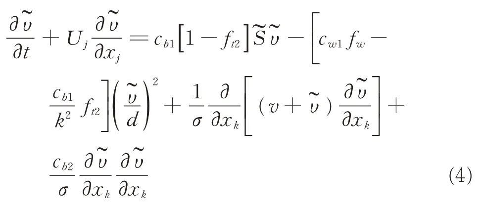
where cb1,cw1,cb2,k and σ are constants;is the modified eddy viscosity,and U is the velocity. The terms on the left side of the equation are the unsteady and convection terms,and the terms on the right side are the production,destruction,dissipation and diffusion terms,respectively.
1.2 SRMS equations
In the SRMS method,for arbitrary grid unit of the rotor disk in the background grids,Eq.(2)is written as

The rotor is represented by the time-averaged momentum sources fijkwhich are averaged throughout the rotor disk plane and added throughout the rotor disk plane at every instant,and are described as

where SΔis the area of a tiny cell on the plane of actuator disk,r is the distance from the center of the rotor hub,dr is the length along the spanwise direction. The reacting force acting on the fluid cell at this location is dF and the resultant force is NdF for N blades.
1.3 BFMS equations
In the BFMS method,the equations are the same as the SRMS method. However,the unsteady source terms fijkare only added to the locations where the blades are actual occurring at every instant,combined with the corresponding aerodynamic force for a background unit,which are described as

The conceptual flowchart for all the computation methods is shown in Fig.1. All the three methods can be divided by the value of the Method,BFMS (Method=1), SRMS (Method=2),RANS(Method=3). 2D airfoil force calculation is only needed in the momentum source methods,when the large amounts of calculations are performed in the RANS method.
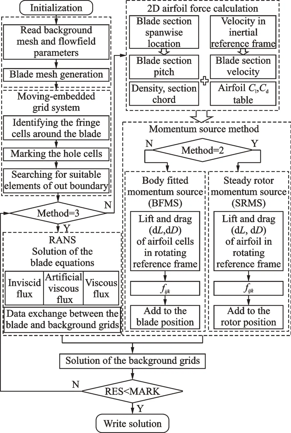
Fig.1 Flowchart of all the calculation methods
2 Body-Fitted Momentum Source Method
2.1 Airfoil environment
To supplement the conventional method,a distribution function of pressure coefficient of twodimensional potential flow for a symmetric airfoil is introduced in Ref.[19]. Though such a chordwise force distribution model adequately predicts the loading on the rotor and furnishes a fair approximation of the unsteady rotor performance,the empirical formula and the experience parameters narrow the range of versatile. These limitations can be overcome by a new distributed force model in which loads of the blade airfoil section is further divided into a series of discrete force unit along chordwise of the airfoil. Fig.2 sketches the aerodynamic environment for a blade airfoil section and the grid cell of the blade element at a certain flight condition.
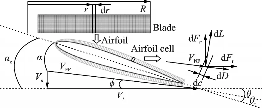
Fig.2 Aerodynamic environment around a blade element
2.2 Calculations of airfoil aerodynamic coefficients
To properly obtain the lift and drag coefficients for each blade airfoil section,it is necessary to determine the magnitude and direction of local velocity,as a result,the angle of attack of airfoil can be obtained. In the traditional methods,the aerodynamic center of the blade section is assumed to substitute the entire airfoil and the blade section properties(such as blade chord,thickness,twist). The normal velocity(Vn)and tangential velocity(Vt)of blade section at a specific spanwise location in the SRMS method can be derived from the average Cartesian velocity components,Vx,Vy,which are given as

Compared with SRMS method,the aerodynamic center of each blade section airfoil in the BFMS method is located inside the blade wall with no flow exist in the current moving-embedded grid system. Therefore,a new approach is developed to determine the magnitude and direction of local velocity of the airfoil.
In this approach,the flowfield of an airfoil can be decomposed into two parts according to the distance away from the wall,one is the near field(NF)of the airfoil which is under the influence of the airfoil,and the other is the far field(FF)away from the airfoil which is considered relative independent of the airfoil flowfield. The interface between two parts is defined as the outer boundary which generally has the certain distance of 2 to 3c(c is the chord of airfoil). Fig.3 shows the simulated flowfield of a blade airfoil section based on the embedded C-type grid system. As can be seen from Fig.3(b),in the far field,the airflow is rarely affected by the airfoil and is nearly coincident with that in the free stream.
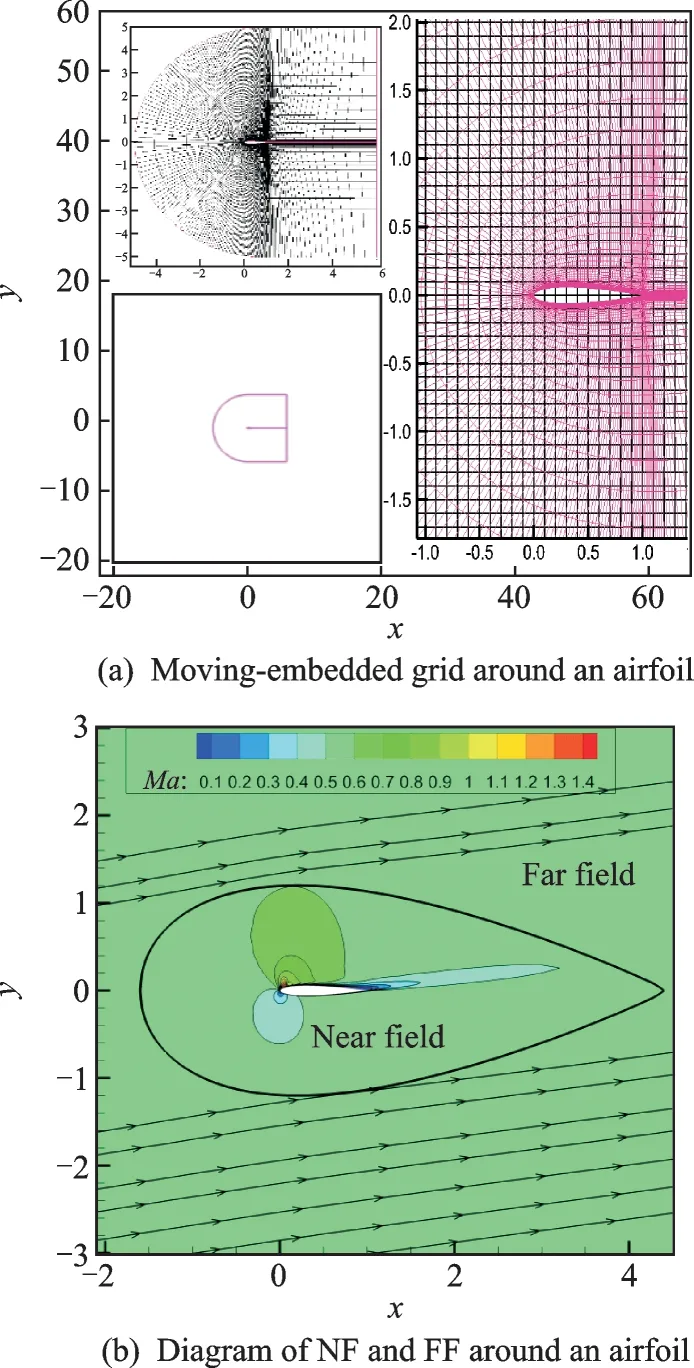
Fig.3 Numerical simulation of an airfoil
The velocity of the outer boundary is regarded as the velocity of the whole airfoil in this investigation,and the normal and tangential velocities of blade airfoil section at a specific spanwise location in the BFMS method can be obtained by
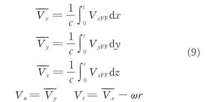
The blade sectional velocity is adopted to determine the local Reynolds Number(Re)and the local angle of attack(α)of the airfoil in the corresponding position of the blade,which is given as

where VFFis the local resultant velocity of the whole airfoil in the far field,μ the viscosity coefficient,θ the collective pitch angle,αgthe geometric angle of attack of a blade section,θtthe geometric twist angle,and φ the inflow angle.
Then α and Re are used to look up the corresponding aerodynamic properties Cl/Cdand dCl/dCdfrom the 2D airfoil characteristics tables established by solving RANS equations. In Fig.4,the calculated lift coefficient and drag coefficient distributions are compared with the experimental data. From the comparisons,it can be observed that the CFD solver makes a reasonable prediction precision of the aerodynamic forces of airfoil.
2.3 Distributed force model
The blade element theory is employed to offer a feasible solution which can be found in many references. It assumes that the blade can be decomposed into a series of blade sections and each section of the blade acts as an isolated 2D airfoil to produce aerodynamic forces(lift and drag). By this method,the overall aerodynamic force of the rotor can be predicted by integrating the resultant 2D air load at each blade section. The lift and drag forces of the blade section in the SRMS method are calculated as
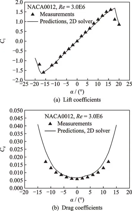
Fig.4 Aerodynamic coefficient distributions of the airfoil
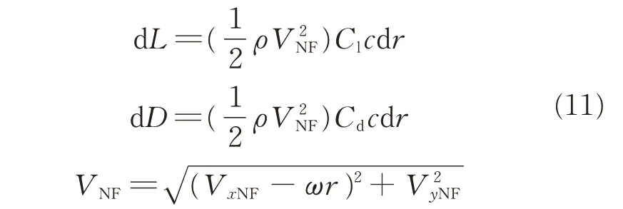
where VNFis the resultant velocity of the whole airfoil in the near field,Cland Cdare the lift and drag coefficients of the airfoil,respectively.
However,the unsteady effect of the rotor blade on its flowfield can hardly be simulated by using the SRMS method because discrete influences due to the aerodynamic characteristics of the blade sections are ignored. This limitation can be overcome by the distributed force model that air load of the blade section is further divided into a series of discrete aerodynamic forces in the blade section,which are written as

where dc is the chord length of the cell of the blade section,and VNFis the resultant velocity of the grid cell of each blade element in the near field.andare the lift and drag coefficients of the airfoil cell,as shown in Fig.1.
The lift force d L(d Ldc)and the drag force d D(d Ddc)of the airfoil(cells)are converted to the normal force d Fnand tangential force d Ft. Momentum source term magnitudes of each cell on the blade airfoil section are easily computed from normal force and tangential force,and are only added to the locations where the blades are actual occurring.

where n is the normal direction of the airfoil and t is the tangential direction of the airfoil.
3 Embedded Grid System
In this paper,the cylindrical structured background grids are adjusted to ensure the high-precision capture of the properties of the flowfield for the hovering rotor. But significant differences of the blade grids are shown in the three methods.3D bodyfitted grids around the blade are adopted in the RANS method,and the actuator disk is taken in the SRMS method,when the 3D surface fitted grids covering the blade surface is used in the BFMS method. Therefore,a new moving-embedded grid methodology is established to satisfy the requirements of the three different grid systems. The embedded grid methodology can be broke down into the following three steps.
Step 1Identifying the fringe cells around the blade surface. The fringe cells in background grids that bounding the wall cells of the blade are identified,and the relationship between them are recorded simultaneously.
Step 2Marking the hole cells. On the basis of the known fringe cells,hole cells are marked out by carrying out a collapsing of the hole boundary.
Step 3Searching for suitable outer boundary cells. The suitable outer boundary cells are searched out at a certain distance in radial direction of the blade surface.
3.1 RANS method
In the RANS method,the C-O type body-fitted grids around the blade are adopted. A closed near boundary(BoundaryNF)with a certain distance away from the blade surface is assigned to identify the fringe cells. And the identification of the corresponding donor cells for the outer boundary of the objective zone can be analytically performed as the near boundary,and the outer boundary of the blade grids is taken as the far field. The embedded grid system for the RANS is shown in Fig.5(a). As can be seen from the Fig.5(b),a desired distance away from the blade surface has been satisfied.
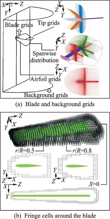
Fig.5 Embedded grid system for the RANS method
3.2 SRMS method
In the SRMS method,the blade grids are acted as a half actuator disk. And the rotor disk is set as the BoundaryNFto identify the fringe cells of the affected area. The embedded grid system for the SRMS method is shown in Fig.6(a). In addition,the affected area of the rotor disk is clearly shown in the Fig.6(b).
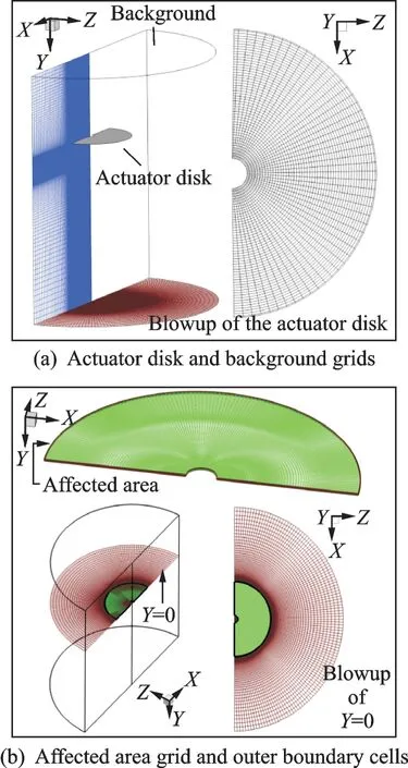
Fig.6 Embedded grid system for the SRMS method
3.3 BFMS method
In the BFMS method,the grids are distributed around a series of two-dimensional airfoils along the radial direction of a blade,resulting in eliminating the need for generating the 3D body-fitted grids of blade. The distribution characteristics of the grid points along the chordwise of the airfoil is the same as that used in the two dimensional N-S equations solver. The blade surface is taken as the near field to identify the fringe cells,when the farfield is selected based on the constant distance away from the blade surface.
For convenience,three-dimensional grids are demonstrated in Fig.7(a),and the suitable outer boundary cells are searched out at a certain distance in radial direction of the blade surface,which are depicted in Fig. 7(b). In hovering flight case,the wake is shedding from the rotor blade tip where the most significant unsteady flow emerges. Therefore,a small distance away from the blade surface is required for simulating the tip vortex with minimal interpolation error. The locations are much convenient to be found out by the embedded grid methodology established above.
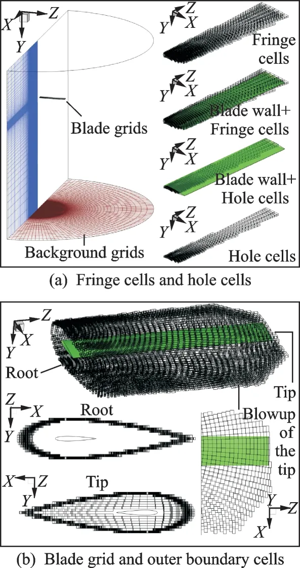
Fig.7 Embedded grid system for the BFMS method
4 Computational Results
In order to verify the BFMS method,several flow simulations for the two-bladed Caradonna-Tung rotor are conducted by using the RANS/SRMS method based on the embedded grid system,and the calculated results are compared with experimental data respectively. The grid information about the different embedded grid systems for the RANS/SRMS/BFMS methods is shown in Table 1.

Table 1 CPU time ratio of each term
For the purpose of comparison,the grids on the blade wall in the two methods(BFMS and RANS)are established based on the same distribution. The BFMS method spends almost the same computational time as the SRMS method when the background grids around the blade are the same for both methods. As a result,the BFMS method has similar computational efficiency with the SRMS method. There is approximately 1.7 CPU hours for the BFMS/SRMS method and 9.0 CPU hours for the RANS method by using 1 CPU processor(Table 1)to reach the convergence of the flowfield for coarse-grained grid application. In contrast with the RANS simulations,it can be concluded that the BFMS/SRMS method only required less than 1/5 of the CPU time consumption of the RANS method. The reason for this acceleration capability of BFMS and SRMS method is the degradation of the proportion of blade shares in the whole computational burden and an accelerating performance in the convergence of the flowfield.
Fig. 8 depicts the aerodynamic load distributions along the spanwise of C-T rotor with different collective pitch angles. It can be observed that the blade lift coefficient calculated by the SRMS method is greater than the experimental data[22]in the inboard region of the blade.However,the variation trend of the results calculated by the steady momentum source is consistent with the experimental data,and the RANS results based on the fine background grids exhibit closest to the experimental data among these methods. It can be seen that a good agreement is observed among the BFMS results and the experimental data as well as the RANS results in the same background grids. The little discrepancy in the outboard region of the blade is due to the absence of empirical tip correction technique such as Prandtl's tip loss model or other empirical factors in the BFMS method,which is often adopted to account for the actual three-dimensional effects at the rotor tip in the SRMS method. Considering the calculation accuracy and efficiency,the comprehensive capability of the BFMS method is best among these methods.
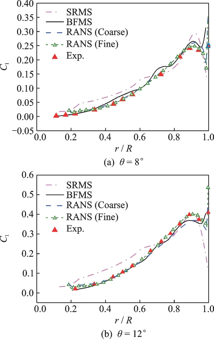
Fig.8 Aerodynamic load distribution along the spanwise of blade (Matip=0.439)
Based on the same coarse background grids,pressure coefficient distributions on the rotor blade and the tip vortex behavior under the rotor at Mtip=0.439,θ=8° are given in Fig.9 and Fig.10,respectively. It can be seen that the BFMS method makes a reasonable prediction of the pressure coefficient distributions on the blade. Though the RANS results are closer to the experimental data in the prediction of pressure coefficient distributions compared with the BFMS results,the BFMS method is more highly-efficient. And the BFMS method predicts the tip vortex pattern as good as the RANS results,which can be observed in Fig.10.
Compared with the RANS results and experimental data,the results show a little discrepancy with the calculated results by the BFMS method.These considerable results are obtained largely due to the reasonable simplification by distributed force model adopted in the BFMS method. Rather than the high complexity of the turbulence model and the high quality grid resolution employed in the RANS simulation,the calculated results show that the runtime of the proposed BFMS method is short and the relative error is acceptable.
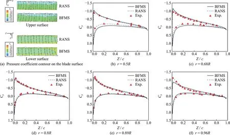
Fig.9 Pressure coefficient distributions on the different blade sections
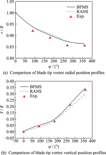
Fig.10 Tip vortex behavior of rotor in hover
To further verify the BFMS method,a series of different conditions simulated by the BFMS and RANS methods for C-T in hover based on the same coarse background grids are shown in Fig.11. It can be observed that the spanwise load distribution calculated by the BFMS method is nearly as good as that from the RANS simulations. Though there is a little computation discrepancy in the region close to the blade tip,this relative error is acceptable. So,the BFMS method can be employed as an effective approach for predicting rotor aerodynamic force with a low computational burden.
Fig.12 depicts the vorticity magnitude for the rotor in hover. It can be seen that the good agreements are observed between the BFMS and RANS results. The little computation discrepancy in the outboard region of the blade is due to the absence of any empirical tip correction technique in the BFMS method,which is usually required to account for the actual three-dimensional pressure distribution at the rotor tip in the SRMS method. However,the results indicate that the BFMS method has its capability to accurately predict the vorticity magnitude around the rotor blades.
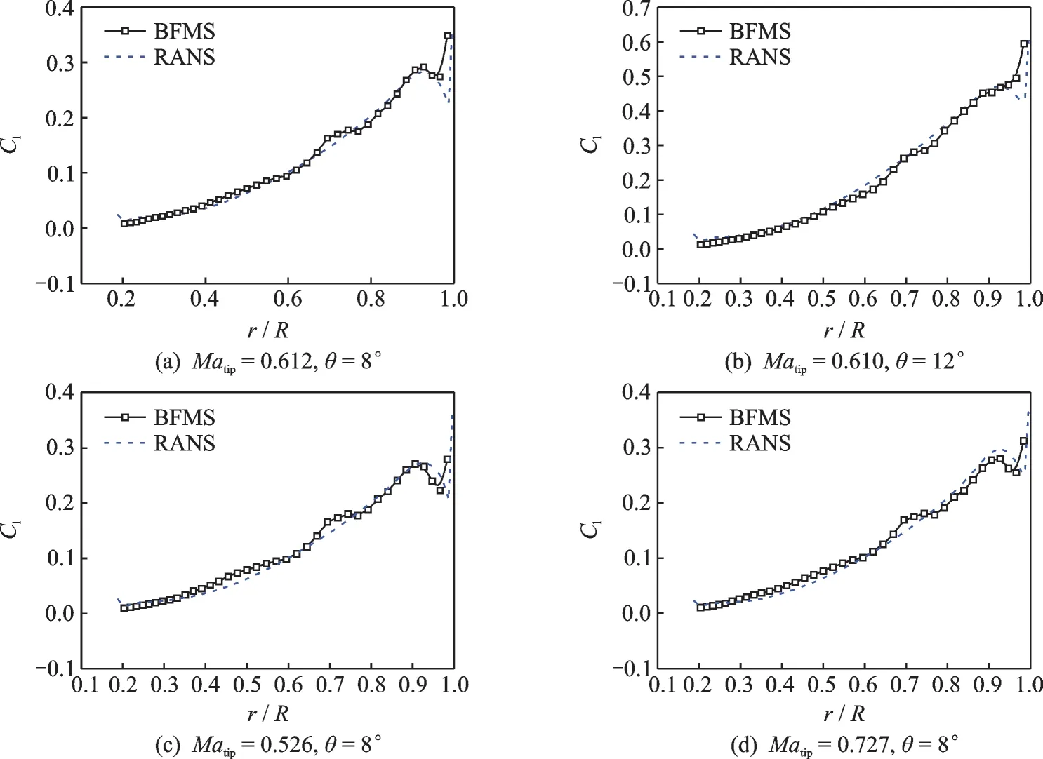
Fig.11 Aerodynamic load distribution along the spanwise of blade at different situations

Fig.12 Vorticity magnitude of the rotor at Matip=0.610,θ=12°
5 Conclusions
In this paper,BFMS method is proposed to simulate aerodynamic characteristics of rotor in hovering flight. To validate the BFMS method,a series of numerical simulations are carried out by the BFMS/RANS/SRMS method respectively. By comparing with the experimental data available and the RANS/SRMS results,the following conclusions can be drawn:
(1)The proposed BFMS method is not only capable of capturing the detailed characteristics of flow around rotor in hover by employing the new distributed force model,but also can account for the blade aerodynamic forces reasonably.
(2)The new embedded grid methodology can connect the blade grids with the background grids,and it is shown to be effective and robust in searching the corresponding donor cells and getting the corresponding information around the blade for all the three methods.
(3)The BFMS method retains the efficient property of the SRMS method,and only need 18%CPU time consumption of the stand-alone RANS calculations in the same background grids. So the BFMS method can be used to substitute the RANS method in the highly efficient simulations on aerodynamic characteristics of the rotor and rotor-fuselage interactions.
杂志排行
Transactions of Nanjing University of Aeronautics and Astronautics的其它文章
- Performance Analysis and Power Allocation for Cooperative SSK System with Receive Correlation in Rayleigh Fading Channel
- Retro-reflective Beamforming Technique with Applications in Wireless Power Transmission
- A 60 GHz Phased Array System Analysis and Its Phase Shifter in a 40 nm CMOS Technology
- Design of Power Amplifier for mmWave 5G and Beyond
- MoM-PO/SBR Algorithm Based on Collaborative Platform and Mixed Model
- Low-Complexity DOA Estimation of Noncircular Signals for Coprime Sensor Arrays
