Numerical simulation of flow separation over a backward-facing step with high Reynolds number
2019-07-24FangfangWangShiqiangWuSenlinZhu
Fang-fang Wang, Shi-qiang Wu*, Sen-lin Zhu
State Key Laboratory of Hydrology-Water Resources and Hydraulic Engineering, Nanjing Hydraulic Research Institute, Nanjing 210029, China
Abstract Large eddy simulation (LES) explicitly calculates the large-scale vortex field and parameterizes the small-scale vortices. In this study, LES and κ-ε models were developed for a specific geometrical configuration of backward-facing step (BFS). The simulation results were validated with particle image velocimetry (PIV) measurements and direct numerical simulation (DNS). This LES simulation was carried out with a Reynolds number of 9000 in a pressurized water tunnel with an expansion ratio of 2.00.The results indicate that the LES model can reveal largescale vortex motion although with a larger grid-cell size.However,the LES model tends to overestimate the top wall separation and the Reynolds stress components for the BFS flow simulation without a sufficiently fine grid. Overall, LES is a potential tool for simulating separated flow controlled by large-scale vortices.
Keywords: Large eddy simulation; κ-ε model; Backward-facing step; Direct numerical simulation; Large-scale vortices; Particle image velocimetry
1. Introduction
Flow over a backward-facing step (BFS) is a common phenomenon in practical engineering, such as the internal flows in diffusers,turbines,combustors,or pipes,and external flows over aircrafts, around buildings, or over stepped channels. These flows are characterized by flow separation and reattachment induced by sharp expansion of the configuration.BFS studies help to provide data that can be used to develop and test numerical codes (Eaton and Johnston, 1981). Significant achievements have been made in the understanding of BFS flow in recent years (Eaton and Johnston, 1981; Armaly et al., 1983; Panjwani et al., 2009; Barri et al., 2010; Ding and Wu, 2012; Kopera et al., 2014). However, due to the complexity of turbulence, further work on the development and validation of numerical methods of turbulent flow is still needed.
Currently, three kinds of numerical methods are usually used for simulation of turbulent flows. One conventional approach is to solve the Reynolds-averaged Navier-Stokes(RANS) equations, such as the widely used κ-ε model. However,it is inadequate for predicting instantaneous flow features(Ratha and Sarkar, 2015). Direct numerical simulation (DNS)and large eddy simulation (LES) are capable of dealing with this issue (Smagorinsky, 1963; Kobayashi et al., 1992). DNS can directly simulate the complicated turbulent flow without using any other models to simulate turbulent effects(Ding and Wu, 2012). Though this method is not applicable in practical engineering projects,there have been some successful cases of BFS flow (Le et al., 1997; Sch¨afer et al., 2009; Barri et al.,2010; Kopera et al., 2014). However, if all scales (including Kolmogorov's length) of turbulence structure are to be predicted, a large number of grid nodes (NG) are needed(NG~(Re3/4)3, where Re3/4is the ratio of the largest length scale to the Kolmogorov dissipation scale, and Re is the Reynolds number) and a number of time steps (NT) are used(NT~Re1/2)(Kobayashi et al.,1992;Kopera et al.,2014).This amount of computing time poses a challenge for current computational capacity, especially for flow with a high Re value. However, Ding and Wu (2012) performed a DNS simulation for a two-dimensional BFS flow with high Re=44000 and only 16669 grid nodes.They believed that the BFS flow was determined by large-scale vortices with length scales of the same order as the study area. Therefore, good results were obtained although larger grid cells were used(the smallest grid cell was 0.1h, with h being the step height).
LES, which was first proposed by Smagorinsky (1963)and Lilly (1966), explicitly calculates the large-scale vortices and parameterizes the small-scale vortices. Turbulent flow is composed of vortices with various scales from the Kolmogorov microscale to the macroscale of the geometrical configuration (Pope, 2000). In the LES model,large-scale vortices are directly solved, while the small subgrid-scale vortices are solved using some generalized models. The accuracy of LES modeling is affected by the discretization scheme, the grid resolution, and the subgridscale model (Panjwani et al., 2009). The turbulence near a solid wall is often inhomogeneous, requiring a larger number of grid cells, making LES computation timeconsuming and expensive. Therefore, the grid resolution,especially for the wall-bounded flow, largely limits LES applications in practical engineering, and a high-fidelity LES model should resolve length scales from the largest to the inertial scale on the grid scales. For flow with higher Re values, LES might be a suitable option. Many LES simulations have been tested on the BFS flow (Kobayashi et al., 1992; Keating et al., 2004; Yang and Abdalla,2005; Aider et al., 2007; Panjwani et al., 2009; Sarwar et al., 2013).
The selection of the subgrid-scale model is crucial in the LES model. Kobayashi et al. (1992) conducted a LES study on a BFS flow with a constant-coefficient Smagorinsky model and a grid cell number of about 205700. The recirculation length (Xr) was overestimated by this model.Additionally, the results showed that three large-scale vortices in the recirculating region and their variation in size may cause fluctuation of the reattachment location.Sarwar et al. (2013) compared four subgrid-scale models: a constant coefficient Smagorinsky model, a dynamic Smagorinsky model, Deardroff's model, and Vreman's model.Aider et al. (2007) performed a more realistic simulation for the BFS flow; a precursor simulation was used to provide realistic inlet conditions and the computational domain grid nodes reached about 622000. Additionally, Keating et al.(2004) performed a BFS flow study with a larger Re (over 20000) and using over 1300000 grid nodes. They compared two subgrid-scale models (a dynamic eddy-viscosity model and a dynamic mixing model). The simulation results confirmed that the peak of heat transfer efficiency occurred just upstream of the mean reattachment point. This can be explained by the high levels of shear stress fluctuations in the free shear layer. However, the friction coefficient was underpredicted far downstream of the reattachment region,and overpredicted in the reattachment zone.
To verify the precision of numerical simulations, many experimental measurements have been conducted for BFS flow. The advent of particle image velocimetry (PIV) made it possible to study instantaneous flow structure and dynamics of BFS flows (Kostas et al., 2002; Schram et al., 2004; Piirto et al., 2007; Velikorodny et al., 2010; Essel and Tachie,2015; Fan et al., 2015). The results obtained by PIV measurements have usually been compared with numerical simulations (Jovic and Driver, 1994; Le et al., 1997).
In the current study, the LES model and κ-ε model were developed for a specific BFS configuration, and the model results were validated both with experimental PIV measurements and with previously published results.The aim of this study was to test the predictive ability of the LES model for the BFS flow and reveal the coherent vortical structures in this flow.
2. Materials and methods
2.1. LES model
In LES simulation, the variables are separated into two categories through filter functions: one includes the filtered spatial-averaged variables, which are solved directly, and the other includes the unfiltered ones, which are simulated with the subgrid-scale models. The governing equations for the grid-filtered, unsteady, incompressible Navier-Stokes equations include the continuity and momentum equations(Eqs. (1) and (2)):


In the dynamic Smagorinsky-Lilly model, the model parameter Csis computed dynamically with the information provided by the resolved scales of motions (Germano et al.,1991; Lilly, 1992). The concept of the dynamic procedure involves application of a second filter(test filter) having twice the width of the grid filter ΔBoth filters produce a resolved flow field, whose size is between the two filters. The information related to these scales is used to compute the model parameter.
The subgrid-scale models employ the Boussinesq hypothesis to compute the subgrid-scale stresses by means of the following equation:


where can be directly computed from the resolved motion, and the double over-bar represents test-scale resolved quantities.
2.2. Computational domain and grid
The schematic view of the BFS flow in this study is shown in Fig. 1. The expansion ratio Er=Hd/(Hd-h)=2.00 and the aspect ratio Ar=W/h=4.00 (h = 5 cm), where Hdwas the tunnel height downstream of the step,and W was the width of the tunnel. The computational domain consisted of a total longitudinal length of 40h (Lu= 5h, Ld= 35h, and Luand Ldwere, respectively, the tunnel lengths upstream and downstream of the step).
The coordinate frame was defined by the x, y, and z axes,where x indicated the longitudinal direction, and y and z represented the vertical and the spanwise directions,respectively.The origin of the coordinate frame(0,0,0)was located at the step's top edge on the left plane (Fig. 1).
The computational grid included two distinct regional scales with Nx×Ny×Nz=24×20×32(Nx,Ny,and Nzare the number of grid cells in the x,y,and z directions,respectively)in the upstream region and Nx×Ny×Nz=210×40×32 in the downstream region (284160 cells and 302808 nodes). The grid was non-uniform in the vertical and longitudinal directions and uniform in the spanwise direction,and was specifically refined near the wall boundaries and in the strong shear layer.Grid refinement tests were performed through a previous LES study of a twodimensional BFS model (Bouterra et al., 2011). They finally concluded that the grid of 104 × 66 cells with a geometric dimension of 18h × 4h was sufficient to carry out a numerical study of the flow with Re=33000.This means a grid density of 5.8/h in the longitudinal direction and 16.5/h in the vertical direction.In this study,a grid density of 5.9/h in the longitudinal direction and 20/h in the vertical direction was employed.
2.3. Flow conditions
The computational domain Ω can be defined as follows:

The top and bottom walls were defined as the no-slip condition. On the top plane,

On the bottom plane,


The inlet condition was obtained through the velocity distribution:

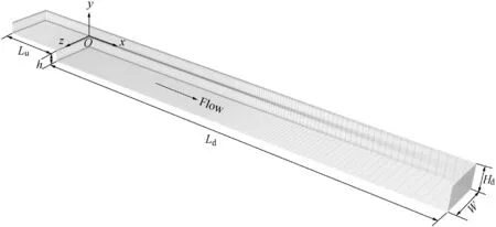
Fig. 1. Study configuration and mesh division (without top and right boundaries).
where m is a fitted parameter, and U0was the maximum velocity of the inflow. They were estimated using the experimental results (m = 250, and U0=0.216 m/s). The time interval was set as Δt=0.005 s.The total simulation time was about 500h/U0. In Fig. 2, velocities were normalized with the mean bulk velocity (Ub), where Ub= 0.82U0was used(Kopera et al., 2014). Unless specifically mentioned, Ubwas used below for normalization.
2.4. Comparison methods
For comparison,the κ-ε model was also tested on the same geometrical configuration with the same grids and boundary conditions, and PIV measurements were used for verification.The experimental measurements were conducted in a horizonal rectangular water tunnel with a step height of 5 mm,an expansion ratio (Er) of 2.00, and an aspect ratio (width-toheight, Ar) of 10.00. Two-dimensional longitudinal velocity distribution was obtained at the central profile. Results were compared among four methods:the κ-ε model,the LES model,the PIV measurements,and the previous DNS study of Kopera et al.(2014).As shown in Table 1,these four methods used the same values of Re=9000 and Er=2.00.As for the spanwise width, Le et al. (1997) reported that a periodic length of Lz= 4.00h was adequate to tail off the two-point correlations for velocities (u, v, and w) near the wall. To reduce the computational burden, the aspect ratio Ar= 4.00 was applied in the κ-ε model and the LES model with symmetry boundary conditions, and Ar= 10.00 in the PIV method to ensure the two-dimensionality of flow (Bradshaw and Wong, 1972).
3. Results and discussion
3.1. Mean flow structure
Fig. 3 compares the time-averaged velocity field and streamlines around the step at the center profile. There is a large recirculation region(primary bubble)behind the step and a smaller one (the secondary vortex) at the deep step corner.The primary bubble and the secondary vortex are separated by two red dotted lines, which divide the flow domain into three regions (the main flow region A, the recirculation region B,and the corner region C in Fig. 3(a)). All these pictures show that the primary bubble center is located at about x = 0.5Xrand y = -0.5h.
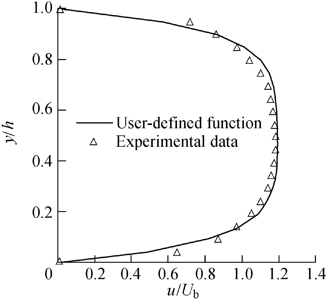
Fig. 2. Inlet velocity profile.

Table 1Summary of parameters for four methods.
The distributions of the mean velocity and streamlines generated by the LES model (Fig. 3(d)) and the DNS method(Fig. 3(a)) agree with the PIV results (Fig. 3(b), as the reference).However,the center of the primary bubble generated by the κ-ε model(x/h ≈0.45) is more towards the upstream and the secondary vortex is compressed and becomes smaller in space (Fig. 3(c)). The results of the LES model show that the secondary vortex looks like a gourd, in contrast to the results of the other methods. This mean vortex may be a signature of the tertiary vortex induced by the backflow separation from the bottom wall, and this separation phenomenon is also verified in the instantaneous streamlines in the PIV measurements.
The recirculation length, Xr, is an important parameter for the BFS flow.It is expressed as the longitudinal distance from the step to the reattachment point. Here, Xrvalues of 6.9h,6.7h, and 6.8h were obtained for the PIV method, the κ-ε model, and the LES model, respectively. The simulation results from the LES model were well verified by the experimental measurements and the κ-ε model. However, the DNS method predicted a relatively larger value, Xr= 8.6h. For further verification, some other similar studies are listed in Table 2. In this study, the Xrvalues from experimental (PIV measurements) and numerical results (LES model and κ-ε model) were consistent with the previous studies. However,the DNS method from Kopera et al. (2014) seems to overestimate this parameter.
3.2. Velocity profiles
Velocity distributions were compared quantitatively at four typical vertical profiles. The first three profiles presented typical positions of the primary bubble (x/Xr= 0.06, 0.46,and 0.93) and the last one was located in the recovering region (x/Xr= 2.32). Non-dimensional longitudinal velocity(U = u/Ub) and vertical velocity (V = v/Ub) were compared among these four methods(Figs.4 and 5).The distributions of U agree with each other except for some divergences around the top wall, especially for x/Xr= 0.93 (Fig. 4). The distribution of V shows that the LES model overpredicts the downward trend at x/Xr= 0.93, and this seems to induce the nonconformity of the separation on the top wall as well.Inadequate fine meshes are likely to reduce the simulated accuracy for the subgrid-scale vortices, and some artificial errors will be imposed upon the calculation.
观察组副反应率10.34%(6/58),低于对照组的27.59%(16/58)(P<0.05)。见表2。
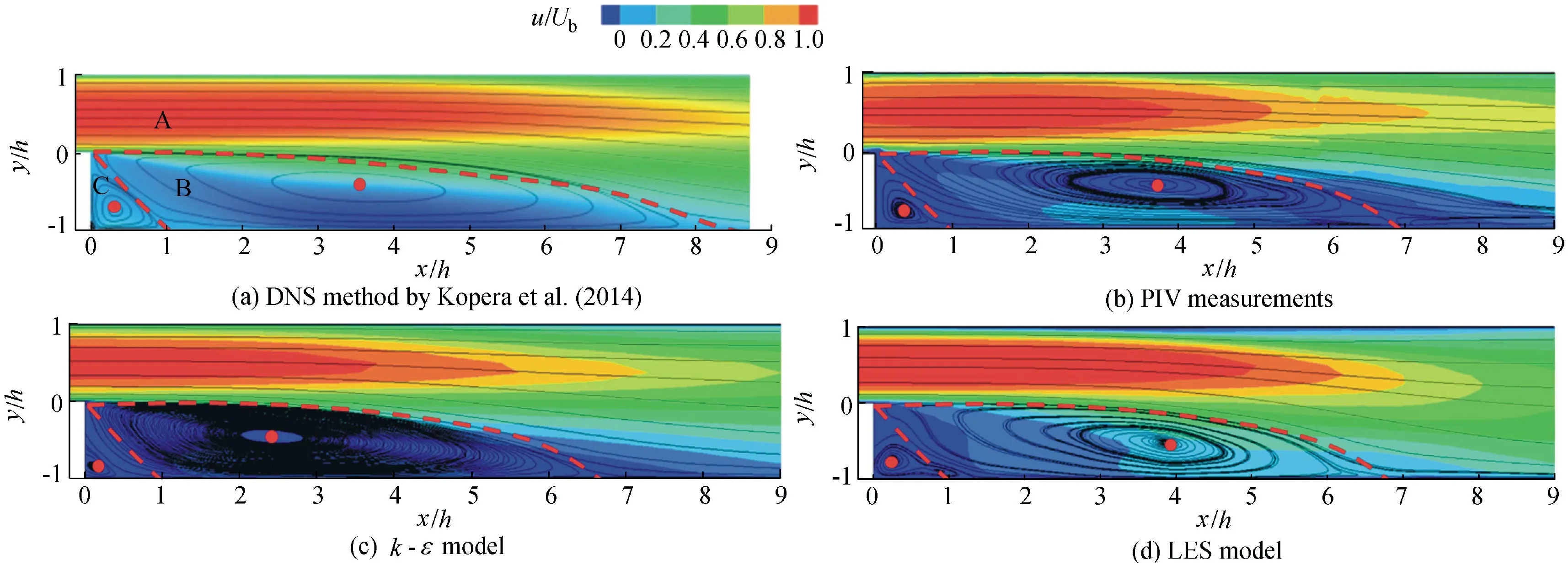
Fig. 3. Time-averaged velocity field and streamlines at center profile.

Table 2Comparison of Xr and maximum Reynolds stress components.
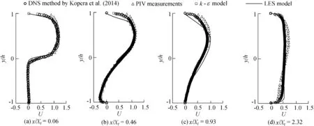
Fig. 4. Comparison of non-dimensional U profiles.
3.3. Static pressure coefficients
An adverse pressure gradient is believed to lead to recirculation behind the step (Eaton and Johnston, 1981; Armaly et al., 1983). Usually, the pressure coefficient (CP) is used to describe the time-averaged static pressure distribution, which can be defined as

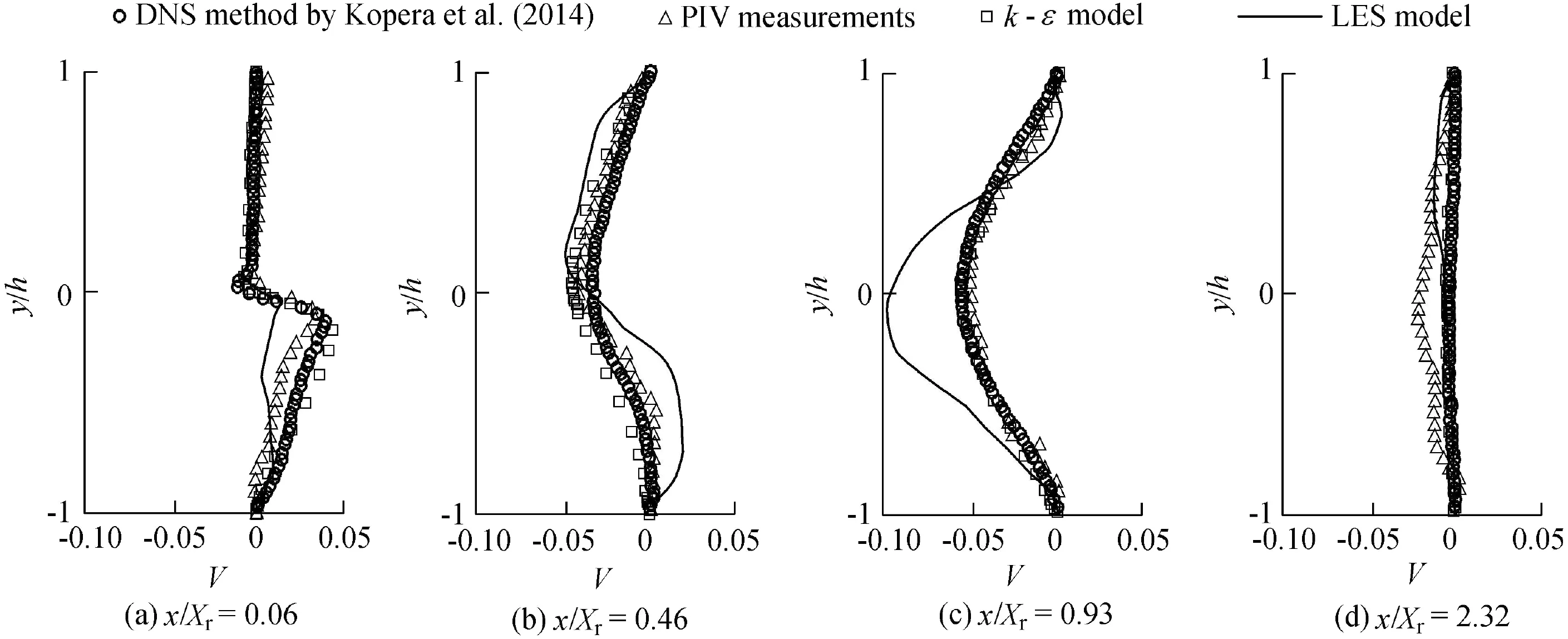
Fig. 5. Comparison of non-dimensional V profiles.
where P0is a reference pressure at x = -4h and y = 0.5h, as suggested by Kopera et al. (2014).
Fig. 6 compares the Cpdistributions of the LES model and the previous DNS study. The Cpvalues computed by the LES model range from -0.14 to 0.51, and their distribution trends agree with the DNS results. There is a clear drop zone originating from the step edge and spanning upward at approximately 0.5Xr, which generates a low-pressure area there. A sharp increase of pressure occurs before the reattachment point(from x ≈3h to x ≈7h).After that,it remains relatively stable in the recovery process.
Fig.7 compares the static pressure coefficient Cwusing the reference pressure Pwtaken at respective top wall at the four profiles (Kopera et al., 2014). The pressure intensities between the DNS and LES methods in the recirculation area(x/Xr= 0.46) and reattachment zone (x/Xr= 0.93) are quite different, while for the other two profiles (x/Xr= 0.06 and 2.32) they agree. Kopera et al. (2014) explains that the pressure deficit mainly occurs in the mixing layer and the solid boundary throughout the outflow channel in the recirculation area. Compared with the DNS method, the LES model is likely to overestimate the adverse pressure in the recirculation area (x/Xr= 0.46), while the pressure increases and surpasses that of the DNS method at the bottom wall in the reattachment zone(x/Xr=0.93).Finally,it returns to a uniform distribution across the channel when the flow recovers(x/Xr=2.32).It can be deduced that the pressure distribution is closely related to the mean velocity (Fig. 4).
3.4. Turbulent intensity and shear stress
Figs. 8 and 9 show the normalized Reynolds stress components (the longitudinal turbulent intensity, the vertical turbulent intensityand Fig. 10 compares the maximum Reynolds stress components along the flow direction between the LES model and PIV measurements. The normalized Reynolds stress components were defined as follows: and the shear stress

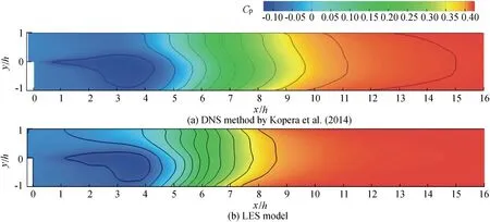
Fig. 6. Averaged pressure coefficient contours Cp from DNS method by Kopera et al. (2014) and LES model.
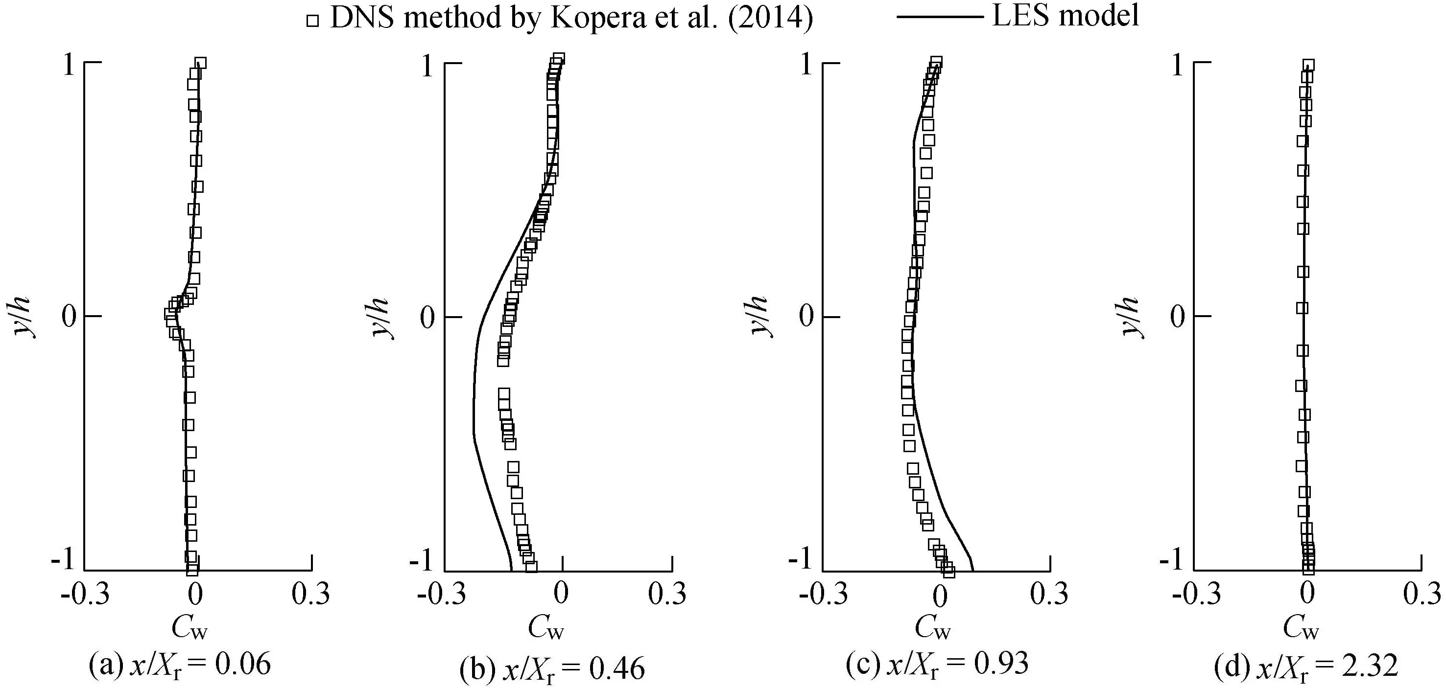
Fig. 7. Comparison of static pressure distribution.

where u′is the turbulent velocity in the x-direction,and u′=u-U;v′is the turbulent velocity in the y-direction,and v′=v-V;and n is the sample number.
The LES model and PIV measurements provide a similar distribution for the three normalized Reynolds stress components (Fig. 8). A high level of turbulence intensity and shear stress occurs in the free shear layer (from x ≈3h to x ≈7h), which may be due to the high mixing rate. The contours show that they emanate from the step edge and accelerate both in width and intensity along the flow direction. However, they decrease sharply when passing through the reattachment zone, and this phenomenon was with the shedding of the large-scale vortices. The step corner region (C in Fig. 3(a)) maintains much lower values as the laminar-like flow is shielded by the step there. In the LES model, the contour ofshows a peak value at the primary bubble center (around x = 4h), and a separation area is clear near the top wall, where it finally mixes with the primary one. The shear stressshows a negative region close to the top wall. However, the top wall separation can hardly be found in the PIV results.
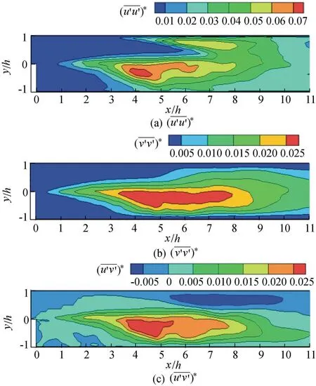
Fig.8.Normalized Reynolds stress components at center profile from LES model.
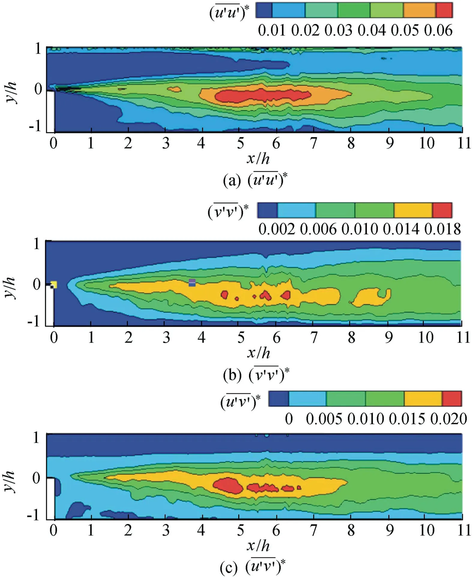
Fig.9.Normalized Reynolds stress components at center profile from PIV measurements.
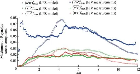
Fig. 10. Distribution of maximum Reynolds stress components along flow direction.

Fig. 11. Normalized turbulent kinematic energy production.
For the maximum value of these parameters, the results of the LES model are in total a little bit larger than those of the PIV measurements,especially for.Differentdistributions occur,particularly before x ≈4.7h.Another peak value is found near the step edge (about x = 0.5h) in the PIV results, while the LES model fails to reproduce it. Before the reattachment point (R), larger values are located at about x = 3h to x = 7h. This region corresponds to the obvious increase of Cp. Therefore, the adverse pressure gradient may contribute to the high rate of mixing by impeding the passage of the large-scale vortices. The maximum Reynolds stress components are also listed in Table 2. The results offrom the LES model are reasonable. However,is overestimated in comparison to the other results.
3.5. Turbulent kinematic energy
Fig. 11 shows distribution of turbulent kinematic energy production at the center profile from the LES model.The twodimensional turbulent kinematic energy production, Pke, is expressed as follows (Scarano et al., 1999):

Pkehas a similar distribution trend to that of the Reynolds stress components. However, its peak value is located around x = 2h at the middle height of the channel, which is further upstream than that of the Reynolds stress components. This was assumed to be induced by the earlier appearance of the large velocity gradients behind the step(Scarano et al.,1999).
The peak value of Pkewas found to be about 0.02 in previous studies(Le et al.,1997;Scarano et al.,1999;Kostas et al.,2002),while the maximum value in this study reached 0.05(Fig.11).A representative profile, x = 4h, was compared in Fig. 12. The peak value in this LES simulation was about twice as large as that of the DNS method(Le et al.,1997)and experimental results (Scarano et al., 1999). A possible reason is the overestimated Reynolds stress values in this LES simulation.
3.6. Instantaneous large-scale vortices
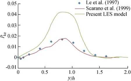
Fig. 12. Comparison of Pke profile with prior studies at x/h = 4.0.
Fig. 13 presents the large-scale vortices in the instantaneous streamlines.Itshowsthat theinstantaneousflow ismoreirregular than the time-averaged flow structure.The free shear layer is full of large-scale vortices (shown by streamlines), and they are rolled up from the step edge and approach the reattachment zone.In the first part of the recirculation bubble, vortices gradually form and develop with increasing size downstream.After that,the developing vortices merge and decompose as they interact with each other. When passing through the reattachment zone,the vortices start to shed and redevelop with the suppression of the bottom wall.This process shows rich vortical behaviors that correspond to the flow structure, and these vortical evolutions may contribute a lot to the time-averaged characteristics. In addition, the streamlines bend where vorticity (wz= 0.5×(∂v/∂x -∂u/∂y))is concentrated.

Fig. 13. Large-scale vortices in instantaneous streamlines simulated with LES model.
Large-scale vortices play an important role in the turbulent flows and contribute greatly to energy or momentum transformation. However, they are usually unavailable in simulations with the time-averaged method, such as the κ-ε model.The LES model performs well in simulation of the instantaneous flow with relatively sparse grids.For BFS flow,although vortices with smaller scales than the sub-grid cannot be reproduced with this model,the main flow features can still be well reproduced. This emphasizes the important role of the large-scale vortices in these strong shear flows.
4. Conclusions
In this study, the LES model and time-averaged κ-ε model were developed for a specific BFS geometrical configuration,and compared with the DNS method and PIV measurements.The following conclusions can be drawn:
(1)The LES model can predict the mean flow structures of BFS flow well, while the DNS method tends to overestimate the recirculation length as compared with the LES model, κ-ε model, and PIV results.
(2) The LES model cannot effectively simulate the boundary layer near wall areas without sufficiently fine grids and it tends to overestimate the top wall separation. As a result, mean velocity, static pressure, Reynolds stresses, and the turbulent kinematic energy all show a larger peak value than they do with other methods.
(3) The LES model can successfully simulate the instantaneous large-scale vortices in BFS flow. Although vortices with smaller scales than the sub-grid are generalized in the LES model, the main flow features can still be reproduced.This emphasizes the important role of the large-scale vortices in these strong shear flows.
Results from this study can provide a reference for engineering applications of the LES model with limited computation capacity.
猜你喜欢
杂志排行
Water Science and Engineering的其它文章
- Flume experimental study on evolution of a mouth bar under interaction of floods and waves
- Porosity and permeability variations of a dam curtain during dissolution
- Possibilities and challenges of expanding dimensions of waterway downstream of Three Gorges Dam
- River bank protection from ship-induced waves and river flow
- Submerged flexible vegetation impact on open channel flow velocity distribution: An analytical modelling study on drag and friction
- Correlations between silt density index, turbidity and oxidation-reduction potential parameters in seawater reverse osmosis desalination
