Investigation on the Helium-foil of Highly Loaded Helium Compressor*
2019-06-18ZhitaoTianQunZhengBinJiangYuDuan
Zhi-tao Tian Qun Zheng Bin Jiang Yu Duan
(Harbin Engineering University,College of Power&Energy Engineering,Harbin,China)
Abstract:After many years development, the air compressor has formed a set of blade type (airfoil) which is suitable for air compressor design from low speed to high speed.Helium has a high sonic speed,and newly devised the expansion and contraction structure of the helium cascade after highly loaded design is obviously different from the structure of the air compressor. Therefore, it is necessary to develop a set of helium blade (helium-foil) with low dissipation loss for highly loaded helium compressor.In this paper,a type of helium-foil is presented.The performances of this helium-foil are compared with the CDA by numerical simulation.The results show that the total pressure loss coefficient of the helium-foil is 5%lower than that of the CDA and the surge margin of the helium-foil compressor is 3%higher than that of the CDA.
Keywords:Helium compressor,Helium-foil,Numerical simulation,Loss
Nomenclature
h Enthalpy
p Pressure
i Incidence angle
C Actual chord length of blade
U Rotor tangential velocity
V Gas absolute velocity vector
W Gas relative velocity
G Mass flow
αGas absolute angle
βGas relative angle
ηIsentropic efficiency
ωˉTotal pressure loss coefficient
φStage load coefficient
Cp Static pressure coefficient
CDA Controlled-diffusion airfoil
OPT Optimized profile
Subscripts
0Design point
1Inlet
2Outlet
Superscript
*Stagnation
1 Introduction
Helium compressor is one of the key components of high temperature gas cooled reactor with the direct helium cycle which plays an important role in the performance of the high temperature gas cooled reactor [1-4]. The major challenge in helium based system is the compressibility of the gas.It is difficult to compress helium due to its thermodynamic properties. Helium compressor needs higher number of stages to achieve a certain pressure ratio then air compressor[5].This makes the shaft of helium compressor relatively slender and then serious vibration problems are caused [6].In order to solve the above problems,reduce the stages of helium turbomachinery, improve the power density of the closed Brayton cycle that achieve a better applications in nuclear power.The highly loaded design method of helium compressor is proposed [7]. This design method has greatly promoted the performance of helium compressor which has the same single stage pressure ratio with the air compressor.
But the modern highly loaded helium compressors used in Close Brayton Cycle have to deal with a number of requirements. Due to economic and ecological demands, high efficiency as well as higher power output, based on both growing mass flows and increasing specific work, is desired.The stacking pattern of the profiles in the radial direction, as well as the profiles themselves, plays an important role for the efficiency of the whole compressor.
In the past, a series of airfoil have been developed for used in subsonic compressor design. Based on a large number of experiments, the NACA airfoils [8] were developed by National Advisory Committee for Aeronautics(NACA)in 1940. And the NACA airfoils were widely used in many aeroengine and heavy-duty gas turbines. The controlled-diffusion airfoils(CDA)were also developed based on both experimental and numerical research work [9]. The appearance of controlled-diffusion airfoils (CDA) made their way into modern compressor design. Although the NACA airfoil and CDA have achieved great success in the application of aeroengines and gas turbines[10-11],it's hard to succeed in highly loaded helium compressor because newly devised of the expansion and contraction structure of the helium cascade which is obviously different from the structure of the air compressor after highly loaded design.
In this paper, a helium-foil of highly loaded helium compressor is developed by numerical optimization method.Then the loss of the highly loaded helium compressor with helium-foil is analyzed.The performances of this helium-foil are also compared with the CDA by numerical simulation.At last, the influence of blade type on three-dimensional flow is also studied.
2 Highly Loaded Design Method
The velocity vectors and associated velocity diagrams for a typical highly loaded axial helium compressor stage and a conventional axial helium compressor stage are compared in Figure 1. The velocity triangle of the highly loaded helium compressor differs greatly from that of conventional helium compressor. Based on the characteristics of high sound speed of helium,the velocity triangle of highly loaded compressor increases the torsional velocity greatly by increasing both the axial velocity and a negative pre-whirl[12-15].As shown in Equation 1 and Equation 2,if the circumferential velocity is unchanged, the stage load coefficient will increase greatly.
The stage load coefficient can be defined as:

The enthalpy rise along the streamline is given as follows:

WhereΔWu=W1u-W2ufor the conventional helium compressor ΔWu=W1u+W2ufor the highly loaded helium compressor.
3 Optimization System
The optimization purpose is to find the extremum of the objective function in the independent variable domain of the given constraint condition.The optimization of the compressor blade type is to take the parameterized geometric parameters of the compressor blade as independent variables and the aerodynamic performance of the blade as the objective function.And then solve the extremum problem. The parametric expression of blade type, the selection of optimization variables and the determination of objective function affect the difficulty of solving the whole optimization process and the efficiency of the optimal solution. This optimization system has been introduced by Jiang [16], so I won’t reiterate them here.Figure.2 shows the optimization design flow chart.

Fig.1 Velocity diagram in helium compressor
4 Numerical Techniques
Figure.3 shows the 2D calculation mesh model.The solidity of this cascade is 1.8. The inlet is set in a distance equal to 2 chords up-stream of the blade and the outlet is set in a distance equal to 2 chords down-stream of the blade.
For the 3D model, the number of blade is 145 and the form of the flow passage of the helium compressor is constant inner diameter. The inlet is set in a distance equal to 2 chords up-stream of the rotor and the outlet is set in a distance equal to 2 chords down-stream of the rotor.
In each flow-path, the periodic multi-block O4H-type structured grid is used which is created by Autogrid5 (NUMECA preprocessor). O-type grids surround the rotor surface and H-type grids are in the remaining regions. Figure.2 shows the grids system of rotor. The cell-centers adjacent to the solid surfaces are placed at y+<1 for all the computations.
The numerical simulation software used in this paper is the commercial flow solver ANSYS-CFX17.The solution results are gained by solving the 3D steady compressible Reynolds-averaged Navier-Stokes equations and to discretize the equations, a finite-volume method is used. The SST turbulence model is used for the closure of the discretized Navier-Stokes equations which is fit for highly loaded compressor and boundary layer calculation[17].

Fig.2 Optimization design flow chart

Fig.3 2D calculation mesh model
The computations are performed by considering a single blade passage with periodic boundary conditions imposed along the boundaries in the circumferential direction.Total temperature and total pressure are specified along with the flow angle at the inlet. At the outlet, static pressure is specified.All solid surfaces are supposed to be adiabatic and no-slip.
To eliminate the effect of grid size on the flow solutions, the investigation of a grid-independence is performed on the rotor. Under the same outlet pressure condition, five different numbers of grids are calculated.The isentropic efficiency is shown in Figure.5. For the isentropic efficiency,there is almost no change, when the grid points is observed from 0.73million to 0.92million.The Contours of shroud surface pressure distribution with different grid points are shown in Figure.6. When the grid point number reaches 0.73million, the shroud surface pressure distribution also does not change with the increase of the grid points. In summary, considering the computational accuracy and cost, total number of grid points of the rotor is set to be approximately 0.73 million.

Fig.4 3D Computation mesh for helium compressor rotor

Fig.5 Numerical results with different grid points
5 Numerical Results and Discussion
5.1 Analysis of the Blade Profile Loss
The main parameters of the initialize profile are shown in Table.1. The initialize profile is controlled-diffusion airfoils (CDA) and the position of the maximum thickness is about at 40% chord.The turning angle of the initialized profile is 55.11°.
A helium foil is got by the optimization system. The comparison of the CDA and optimized profile is given in Figure.7. As shown in Figure.7, the trailing edge of the profile gets thickened while the leading edge of the profile changes little. Though the maximum thickness of the profile did not change after optimization, the location of maximum thickness of the optimized profile moves forward compared with the CDA profile.
The static pressure coefficient is a dimensionless parameter related to the static pressure.It can be defined as:
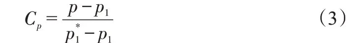
Since the inlet conditions of all cases are the same, the static pressure coefficient can reflect the surface pressure of the blades.

Fig.6 Contour of shroud surface pressure distribution with different grid points

Tab.1 the main parameters of the initialize profile

Fig.7 Comparison of the CDA and the optimized profile
From the static pressure coefficient distribution at 50%height of blade, it can be seen that the pressure of OPT case is lower than that of the CDA case at the minimal pressure point of suction side(Fig.8). And the position of minimal pressure point also moves forward. This means the load of the optimized profile moves forward. The optimized profile has a longer accelerating pressure gradient at the pressure surface which relieves the increase of the boundary layer on the pressure surface and reduces the flow loss of the working fluid.
The comparison of total pressure loss coefficients with different incidence angles between CDA and optimized profile is shown in Figure.9.The loss curve of optimized profile decreases visibly compared with the CDA one, especially at a positive incidence angle.The total pressure loss coefficient of optimized profile decreases 4.2% at the design point and 24% at 6°positive incidence angle. It shows that the optimized profile can suppress the flow separation and reduce the losses of flow in the case of positive incidence angle.
The total pressure loss coefficient along axis at 6°positive incidence angle is shown in Figure.10. It can be seen that the difference of the total pressure loss coefficient between CDA and optimized profile enlarge sharply at the leading edge of the blade.The loss growth of the optimized profile is more moderate than that of the CDA one. There is a loss jump at the trailing edge of the CDA one which means that the flow separation occurred here,while the flow separation of the optimized profile at the trailing edge is not obvious.The flow separation of the CDA one at the trailing edge also increases wake loss.
The Mach number contours of CDA and optimized profile at 6°positive incidence angle are shown and compared in Figure.11.The optimized profile has a higher Maher number than the CDA at the leading edge. This is mainly because of the maximum thickness position of the optimized profile is closer to the leading edge than the CDA one. The optimized profile also has a thinner boundary layer near the trailing edge. This reduces the flow loss of helium effectively. On the pressure surface of the blade profile, optimized profile has a higher Maher number which helps to suppress the accumulation of the boundary layer on the pressure surface.

Fig.8 Static pressure coefficient distributions of rotor at 50%height

Fig.9 Incidence-loss curves
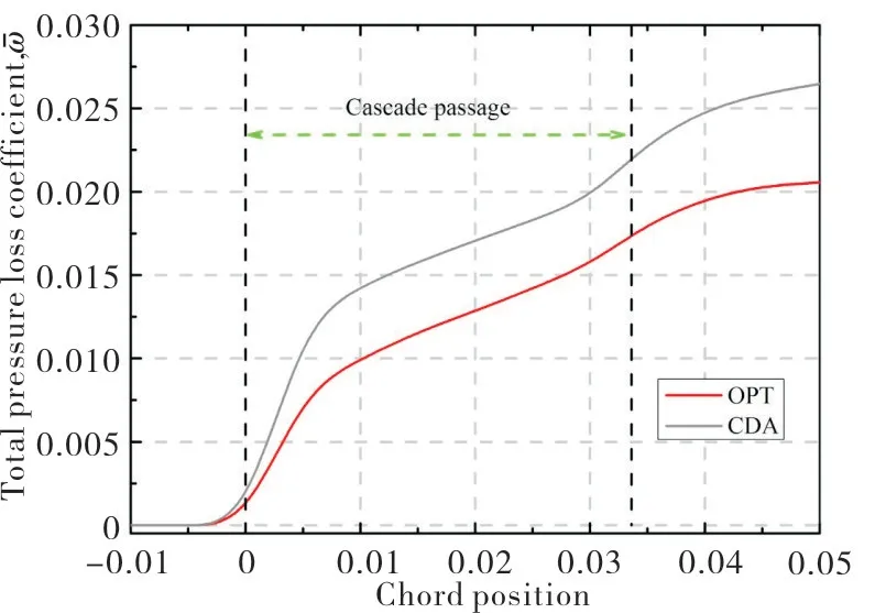
Fig.10 Total pressure loss along axis at 6°positive incidence angle
5.2 Analysis of 3D Flow Loss
The flow in the compressor is a complex three-dimensional flow.The three-dimensional performance of the blade is more important than that of the blade profile in two-dimensional. In this part, the three-dimensional flow loss of the highly loaded helium compressor rotor with the optimized profile is analyzed and compared with the CDA one.
Figure.12 shows the performance maps for the highly loaded helium compressor rotor.Because of using the highly loaded design method, the performance maps of the highly loaded helium compressor is different with the conventional air compressor. The pressure ratio did not increase with the decrease of the massflow but decrease and the reason for this change has been explained in zhi tao T[15].
As shown in Figure.12, both the isentropic efficiency and total pressure ratio of the compressor rotor with the optimized profile are higher than the CDA one.The stable operating range of the compressor rotor is also slightly increased.The compressor rotor with the optimized profile has more obvious advantages under the condition of positive incidence angle.
The total pressure loss coefficient along span at the design point is shown in Figure.13.As shown in Figure.13,the compressor rotor with the optimized profile has less loss at the height of 10%~20% and 70%~90% blade. It means that the optimized profile can inhibit the end wall loss very well.Figure.14 shows the total pressure loss coefficient near the stall point. The optimized profile has a greater advantage than the CDA one in full blade height.

Fig.11 Contour of Mach number(5°)

Fig.12 Performance of compressor at design speed

Fig.13 The total pressure loss coefficient at rotor outlet,G/G0=1.0

Fig.14 The total pressure loss coefficient at rotor outlet,G/G0=0.71

Fig.15 The relationship between relative massflow and relative amount of leakage
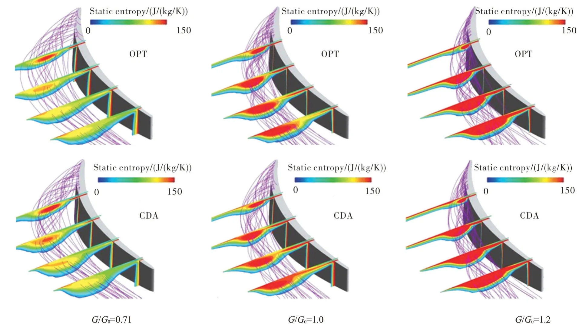
Fig.16 Streamlines and static entropy contours in the tip region

Fig.17 Static entropy contours in the corner region
The relationship between relative massflow and relative amount of leakage are shown in the Figure.15.The compressor rotor with optimized profile has less leakage at low operating conditions and the compressor rotor with CDA has less leakage at high operating conditions. This is mainly due to the difference in the thickness distribution of the blade. The change of relative leakage can also be reflected from the contours of static entropy.
Figure.16 shows the streamlines and static entropy contours in the tip region.With the increase of the massflow,the strength of the leakage vortex increases obviously and the starting position of the leakage vortex moves backward. The compressor rotor with optimized profile has a weaker leakage vortex at low operating condition than the CDA one.Under design conditions, the advantage of the optimized profile is not obvious. However, when the compressor operates at high operating conditions, the compressor rotor with optimized profile has a stronger leakage vortex. This is mainly because of the compressor rotor with optimized profile has relatively large leakage at high loading conditions.
The static entropy contours in the corner region are shown in Figure.17. As shown in Figure.17, with the increase of the massflow, the strength of the corner vortex increases gradually and the scale of the corner vortex decreases gradually. The compressor rotor with optimized profile can restrain the development of the corner vortex and reduce the strength of the corner vortex in low working condition.In the case of high operating conditions, the inhibition is not obvious.
6 Conclusions
In this paper, a blade type of a highly loaded helium compressor is optimized by numerical optimization program.The total pressure loss characteristics of the optimized profile are studied and compared with the CDA one. The threedimensional performance of the blade is more important than that of the blade profile in two-dimensional.So,the three-dimensional flow loss of the highly loaded helium compressor rotor with the optimized profile is also analyzed and compared with the CDA one.Conclusions are as followings:
1)The optimized profile is impactful for the highly loaded helium compressor. The blade profile loss of the optimized profile decrease 4.2%at 0 incidence condition.The advantage of the optimized profile is more obvious than initial CDA profile at high positive incidence condition. The blade profile loss of the optimized profile decrease 24% at 5 incidence condition.
2)The highly loaded helium compressor rotor with the optimized profile can reduce the tip clearance loss at high positive incidence condition. However, when the compressor operates at high operating conditions, the compressor rotor with optimized profile has a stronger leakage vortex. This is mainly because the compressor rotor with optimized profile has relatively large leakage at high working conditions.
3)The highly loaded helium compressor rotor with the optimized profile can restrain the development of the corner vortex and reduce the strength of the corner vortex at high positive incidence condition.
4)The effect of blade profile on the three-dimensional flow loss should be considered in the optimization of blade profile. Only in this way can the excellent effect of optimized profile in practical application be achieved.
杂志排行

风机技术的其它文章
- Multi-objective Optimization of a Fan Airfoil Adaptive for the Inlet Distortion*
- Tip Profile Optimization in a Low Aspect Ratio CAES Radial Expander Based on Orthogonal Design*
- The Effect of Compressibility in Computing Noise Which Induced at a Cavitating Device
- Gurney襟翼在离心压缩机叶轮上的数值研究*
- 吸油烟机多叶离心风机的优化与改进
- Effects of S-shaped Duct on Fan Blade Vibration