Tip Profile Optimization in a Low Aspect Ratio CAES Radial Expander Based on Orthogonal Design*
2019-06-18XingWangWenLiXuehuiZhangYangliZhuZhitaoZuoHaishengChen
Xing Wang Wen Li,2 Xue-hui Zhang Yang-li Zhu Zhi-tao Zuo Hai-sheng Chen ,2*
(1.Institute of Engineering Thermophysics,Chinese Academy of Sciences,Beijing,China,*chen_hs@mail.etp.ac.cn 2.University of Chinese Academy of Sciences,Beijing,China)
Abstract:Blade tip profile based on NACA airfoil is firstly introduced into the radial expander to suppress the tip leakage loss. A blade with optimal NACA tip profile is obtained by coupling orthogonal experiment design and Computational Fluid Dynamic (CFD) model. The tip loss reduction mechanism leakage flow is also revealed. The results illustrate that the optimal NACAtip profile presents smaller leading edge inscribed circle radius,thinner trailing edge.The location maximum thickness is close to the front edge.The influence of leading edge inscribed circle radius and maximum thickness location on radial expander’s efficiency is increased with the increase of tip clearance.The blade with optimal NACA tip profile even increases the radial expander’s efficiency by 1.47%when tip clearance is 8%,and it also presents higher efficiency at off-design condition.The blade with optimal NACA tip profile reduces tip leakage flow velocity near the trialing edge region,weakens the mixing strength between leakage flow and mainstream,and therefore decreases flow loss.
Keywords:Radial Expander,Optimization,Blade Tip Profile,CAES,Orthogonal Experiment Design
Nomenclature
D diameter
H enthalpy
l,Llength
m˙mass flow rate
n rotational speed
p pressure
S entropy
T temperature
π pressure ratio
η efficiency
Subscripts
Axialaxial direction
ininlet
outoutlet
tttotal to total
Superscript
* Stagnation state
1 Introduction
As an important power-output device,the radial expander has the advantage of high expansion ratio and compact structure(Ma et al, 2012)[1], and it is widely adopted in micro gas turbine(Fu, et al, 2017)[2], rocket engine(Letoa et al,2017)[3],renewable energy system(Kim,et al,2017)[4],distributed power generation(Rahbar, et al, 2017)[5] and ORC(Orgainic Rankine cycle)system(Kang,et al,2016)[6],et al.
The efficiency of radial expander is an important performance index.Current references have shown that the tip leakage loss influence the efficiency significantly. The studies conducted by Futral et al(1970)[7], Ishino et al(1991)[8],Jones et al(1996)[9] respectively showed that the efficiency of the radial expander decreased by about 1%if the tip clearance increased by 1%. The result obtained by Pereiras et al(2011)[10] illustrate that the tip clearance reduced the turbine maximum efficiency by up to 8% when the tip clearance increased to 4%of blade span.
Until now, a lot of technologies have been developed and adopted in the turbomachinery to suppress the tip leakage loss by decreasing leakage mass flow, limiting entropy production in the overtip gap, and reducing passage turbulence levels. El-Ghandour et al (2010)[11] proposed a new tip shape to control leakage flow. Zhou et al (2013)[12] adopted winglet geometry to suppress the negative effect of tip leakage flow in a turbine cascade.The method of tip blowing was adopted by Volino (2017)[13] to control the tip leakage in a high-pressure turbine cascade. Maesschalck et al (2014)[14] and Lavagnoli et al (2017)[15] conducted blade tip shape optimization to suppress tip leakage flow. Fu et al(2017)[16] developed a novel honeycomb tip to suppress tip leakage flow in a highly-loaded turbine cascade.
Although these method adopted in axial turbine can effectively suppress leakage flow loss, the tip leakage flow characteristics in radial expander is different. The investigation conducted by Futral(1970)[17]illustrated that the radial clearance size near rotor outlet has greater influence on the efficiency of radial turbine compared with the axial clearance at the rotor inlet. The results obtained by Deng et al(2008)[18]illustrated that radial clearance increased at the rotor outlet has about 8.3 times the effect on stage efficiency.They also found that the“scraping flow”caused by relative motion between the shroud and blade tip,and the pressure difference between pressure surface and suction surface of blade, plays an important role on tip leakage flow (Deng et al,2006)[19].
Above published literatures illustrate that the study on optimization in blade tip profile in radial expander is necessary and possibly to be conducted.First,most of related studies are mainly about axial flow turbines (Yoon et al, 2013)[20],and the relevant research in radial expander is deficient.Second,appropriate profile at blade tip can improve the pressure difference distribution between pressure surface and suction surface of blade and reduce the tip leakage flow loss.Finally, manufacturing the radial expander blade with complex shape is feasible because of the development of the five axis NC machine and 3D printing technology.
In the present study,an optimization of the blade tip profile on radial expander’s efficiency is investigated by orthogonal experiment design which is based on Computational Fluid Dynamic (CFD) model. The influence mechanism of blade tip profile on tip leakage flow structure and flow loss is revealed.And the effect of optimal blade tip profile on radial expander’s efficiency at different inlet total pressure is also investigated. The results obtained in the present work can provide a reference for the design and optimization of turbomachinery with similar structure.
2 Research Object
The radial expander adopted in Compressed Air Energy Storage (CAES) system is selected as the research object in present work, and it has special geometry .As shown in Figure 1, the rotor adopted in CAES system has lower low flow coefficient compared to others reported in the literatures,and the average aspect radio is thus decreased,it means that the proportion of tip clearance in blade height is increased, and the leakage flow has more effects on radial expander’s efficiency. In addition, the blade thickness of present radial expander is relatively higher, it also has effect on the aerodynamic performance and provides space for profile adjustment. The detailed geometric parameters are described in Figure 2 and Table 1.
The standard NACA profile is selected as the design prototype for the tip profile optimization in our present work. It has the advantages of better aerodynamic performance. Comparison between the blade with original tip and NACA tip is depicted in Figure 3. Three parameters are adopted to describe the standard NACA profile. As shown in Figure 4, they are Leading parameters, maximum thickness,and clipping location respectively. The leading parameter is a comprehensive index for the leading shape of blade. Higher leading parameter indicates higher radius of inscribed cycle and thickness at leading edge. The location of maximum thickness influences the distribution of NACA profile. And the clipping location mainly influences the thickness in the downstream part of blade.
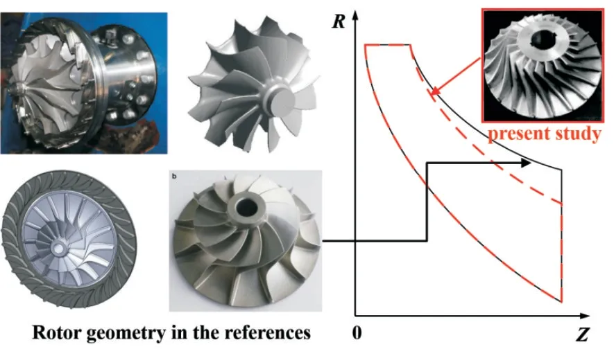
Fig.1 Rotor meridional shape comparison

Fig.2 Definition for the geometric parameters of present radial expander

Tab.1 Operation condition and geometric parameters
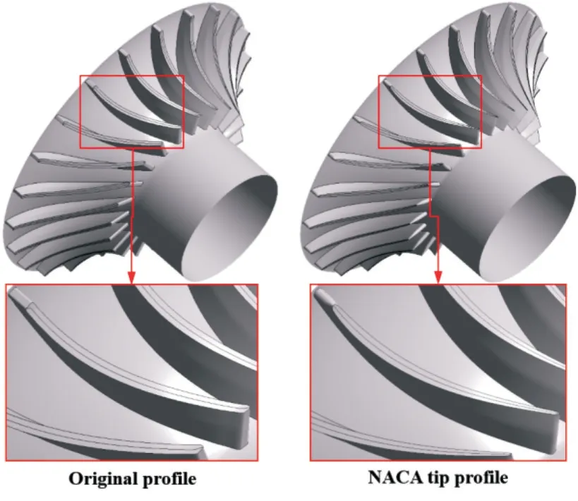
Fig.3 Tip profile comparison


Fig.4 Definition of geometric parameters for blade tip profile
3 Research Model and Method
3.1 Computational Model
The computational model for the present radial expander is depicted in Figure 5.Three-dimensional model with single channel is adopted in the present study. Considering collection chambers are adopted for the radial expanders,boundary conditions is adopted in accordance with the uniformity of the inlet air flow, the uniform total pressure, and uniform total temperature. Flow angles are also specified at the inlet of the model. The average static pressure is specified at the outlet of the model. The inlet turbulence intensity is set to 5%. The rotation speed of the rotor is set based on the requirements of the design operating conditions. The interface between rotating and stationary parts is the“stage interface”,which performs a circumferential averaging of the fluxes through bands on the interface.

Fig.5 Computational domain and boundary condition
The computational mesh for the numerical model is depicted in Figure 6.A structured grid is adopted for the stator and rotor domains.The grid is refined near the wall of the radial expander and tip clearance of the blade to satisfy the requirements of the turbulence model.Generally,the minimum wall y+is less than 1. Based on the result of grid validation,2.0×106elements are adopted for Stages 3.
Gas property tables are adopted to describe the behavior of compressed air to obtain the numerical simulation results of the first stage. The data in these tables are obtained using the REFPROP software,which was developed by the National Institute of Standards and Technology. These tables are generated using in-house developed code.
3.2 Model Validation
The experiment was conducted in our test platform of 1.5 MW CAES system.The total-to-total efficiency is selected as the aerodynamic performance index to conduct the experimental validation. It is obtained by measuring the total pressure and total temperature at inlet and outlet of radial expander respectively by using five-hole probes and temperature sensors. The total-to-total efficiency is defined as follows:

where H is the total enthalpy,p*is the Stagnation pressure,T*is the Stagnation temperature, subscript in represents the inlet of radial expander, and subscript out represents the outlet of radial expander.

Fig.6 Mesh for computational domain

Fig.7 1.5MW scale radial expander test rig
The comparison result of CFD and experiment for totalto-total efficiency is presented in Table 2. The relative error between the predicted and measured total-to-total efficiency is 4.7%, which is less than the allowable deviation of 5% in engineering. The tip clearance sizes at inlet and outlet of the rotor in the CFD model are equal to that in experiment. The error may be caused by the leakage at the shaft end and the variation of blade tip clearance during the operation which are not considered in the present CFD model.
It is a hard task to measure the flow field in the flow channel and blade tip clearance,so there is little test data can be referenced and the direct CFD conparison for the performance and the detailed flow structure is difficult. To further validate the CFD model, NASA turbine in reference (Simonyi et al, 1995)[25] is adpoted to provide an indication for the analysis of tip clearance flow. The geometry and corresponding CFD model of the turbine is presented in Figure 8.
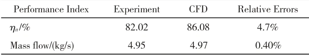
Tab.2 Performance Validation of Radial Expander

Fig.8 NASA radial expander for validation
Further comparison of outlet parameter distributions are shown in Figure 9.It can be found that total to total efficiency,total pressure ratio,total temperature ratio and flow angle obtained by numerical simulation present higher errors at 30%~70% span location. This is mainly due to the outlet of rotor back gap in the experiment. Overall, the calculated disdistributions are basically similar with the experiemtal data(Simonyi et al,1995)[25].

Fig.9 Comparison of outlet parameter distribution for nasa turbine
3.3 Method of Orthogonal Design
The orthogonal design adopts an orthogonal table to manage and analyze a multi-factor numerical experiment. It can intuitively obtain the significance of factors to the required index and optimal scheme by using the minimum number of design schemes. Therefore, the orthogonal design has been widely adopted in the fields of energy (Zhu et al,2014; Feng et al, 2017)[26-27], machinery(Liu et al, 2016;Qu et al,2017)[28-29],biology(Zhang et al,2012)[30].
Figure 10 depicts the process diagram of orthogonal design based on CFD model of radial expander. Total to total efficiency ηttare adopted as the target of the orthogonal design. Maximum Location of Thickness (MTL), Leading Edge Parameters(LP)and Clip Location(CL)are selected as three factors of orthogonal design. The levels for the three factors are shown in Table 3. The CFD model of radial expander is adopted to conduct the orthogonal design.After obtaining the results, significance of MTL, LP and CL to ηttof radial expander can be revealed by range analysis.

Fig.10 Process diagram of orthogonal design based on cfd model of radial expander
An orthogonal array L9(34) is selected in the orthogonal design. The selection of orthogonal array is based on the number of factors and their levels.The column number of orthogonal array should be more or equal to number of factors.In the present study,the orthogonal array of L9(34)with three columns is appropriate for the present study. There are three factors which is equal to the number of column, and there are two levels for each factor.The layout of numerical experiment is listed in Table 4. Three factors are assigned to the columns, and nine trials are assigned to the rows. Due to the properties of orthogonality and uniform scatterance of orthogonal array, nine trials are enough to be conducted to obtain the significance of system parameters to the efficiency of radial expander in the present study.

Tab.3 Factors and levels of orthogonal design

Tab.4 L 9(34)Orthogonal array adopted in present study
The analysis of range (ANORA) is an intuitive method for revealing significance and optimal level of factors to target of orthogonal design.The range R is an index that adopted to reflect the difference between the maximal and minimal values of the results of orthogonal design. The R is defined as:R=max(kij)-min(kij)(2)
where“max(kij)”represents the maximal value of kijand“min(kij)”represents the minimal value of kij; i stands for the factor A-C in Table 3; j stands for the level of the selected factor,from 1 to 3;the range value of R reflects the extent of the variable influencing the indices.The kijin Equation(2) is the estimated index value of factor i at level j in the orthogonal design. The greater the value of R is the more sensitive the factor will be. The level with higher value of kijrepresents the optimal value of the factor.
4 Results and Discussion
4.1 Optimal NACA Tip Profile Analysis Based on Orthogonal Design
Table 5 shows the orthogonal design scheme and its numerical simulation results. It can be found that except for scheme 9, efficiency of radial expander, which with the NACA-based tip profile, is higher than that of prototype blade when tip clearance is 2%,4%and 8%respectively.
Figure 11 depicts the variation of ηttwith NACA profile parameters at different tip clearance. It can be found that maximum thickness location of NACA profile closer to the front edge makes the radial expander performing higher efficiency.As shown in Figure 11(b)and(c),the radial expander with lower LP (Leading Edge Parameters) and higher CL(Clip Location) also present higher efficiency. It means that profile with higher leading edge inscribed circle radius, and lower trailing edge thickness is optimal for the present radial expander.
Figure 12 shows the range analysis results for the profile parameters at different tip clearance.With the increase oftip clearance, the influence degree of trailing edge thickness on efficiency is basically unchanged. However, the influence degree of leading edge parameters and maximum thickness location on efficiency increased with tip clearance.

Tab.5 Orthogonal design scheme and its numerical simulation results (NACA_TIP) efficiency for Tip clearance 2%,Tipclearance 4%,Tip clearance 8%

Fig.11 Variation of ηtt with NACA tip parameters at different tip clearance
Based on the discussion for Figure 11, the optimal NACA profile for blade tip is obtained.As shown in Table 6, it has the parameters of MLT=0.1, LP=3, and CL=0.95. Blade with optimal NACA tip profile presents higher efficiency at tip clearance is 2%, 4%, and 8% respectively, and much more obviously increment in isentropic efficiency is found when tip clearance is 8%. These results illustrate that blade with optimal NACA tip profile allows large tip clearance adopted in the manufacturing radial expander without decreasing the aerodynamic performance of radial expander.
Further tip profile comparison between optimal scheme and orthogonal design scheme is depicted in Figure 13. It can be found that the optimal NACA tip profile presents thinner trailing edge and its maximum thickness location is close to front edge.
4.2 Flow Characteristic Analysis for Optimal NACA Tip Profile
Figure 14 depicts the static entropy distribution in the rotor with original blade and optimal NACA tip profile respectively. When tip clearance is 2%, 4% and 8%, it can be found that a high entropy region, which causes higher flow loss, mainly distributes near the tip clearance at trailing edge of original profile.
Figure 15 depicts the streamline distribution for the tip leakage flow in the rotor. It can be found that the tip leakage flow in the rotor with optimal NACA tip profile presents lower velocity at trialing edge. It illustrates that the mixing strength between leakage flow and main stream is reduced,and the high entropy region shown in Figure 14 is thus suppressed.
Figure 16 depicts the pressure distribution at blade surface of rotor.It shows that the blade surface pressure distribution with fore-loaded type is still found in optimal NACA tip profile,which is same as that of prototype blade.In the blade tip region, the aerodynamic load at the leading and trailing edge of the blade is lower than that of the prototype blade,which effectively reduces the leakage velocity and its mixing strength with mainstream. However, the blade aerodynamic load of optimal NACA thickness distribution is slightly increased, therefore, the power output of it is not significantly reduced.
4.3 Effect on Aerodynamic Performance of Radial Expander
CAES system is always operated under different load to meet the requirement of power grid. Therefore, inlet total pressure of radial expander is also variable during the operation. In the present study, the effects of optimal NACA tip profile on isentropic efficiency of radial expander at off-design condition is also investigated.
As shown in Figure 17, it can be found that the radial expander with optimal NACA tip profile also presents higher efficiency at different operational pressure ratio. Furthermore, much more obviously increase in isentropic efficiency can be obtained by the blade with optimal NACA tip profile when tip clearance is 8%.It illustrates that the blade with optimal tip profile can still improve the efficiency of radial expander,under off-design condition of CAES system.
4.4 Strength Validation of Blade With Optimal NACA Tip Profile
The strength of blade with optimal NACA profile distribution is also investigated in our present work. Figure 18 shows the finite element model of radial rotor. As shown in Figure 18, the rotational speed at design condition is adopted.A displacement constraint is applied on the shaft hole surface. Circumferential displacement constraint is adopted as periodic boundary to realize the strength analysis for full rotor.The aerodynamic load is solved by CFD software and applied on the blade solid surface by one way fluid-solid coupling method.
Figure 19 depicts the finite element analysis results for the rotor blade.It can be found that maximum total deformation of the rotor is 1.45×10⁻⁴m,which meets the size requirement of blade tip clearance; the maximum equivalent stress of the rotor is 7.24×10⁷Pa,which is less than the tensile yield strength of aluminum alloy(2.80×10⁸Pa).
5 Conclusions
In the present study, rotor blade with optimal NACA tip profile is also provided. The influence mechanism of blade thickness distribution on tip leakage flow is also investigated.The corresponding conclusion can be drawn as follows:

Fig.12 Range of NACA tip profile parameters at different tip clearance
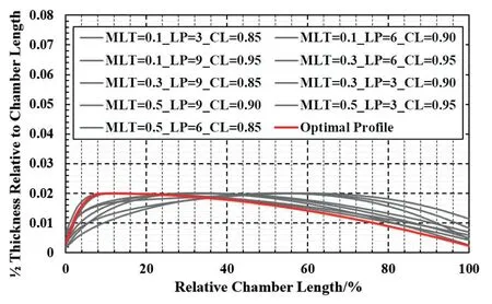
Fig.13 Profile Comparison between Optimal Tip Profile and Orthogonal Experiment Scheme

Tab.6 Total-to-total efficiency comparison for optimal scheme

Fig.14 Entropy distribution in rotor


Fig.15 Streamline distribution in rotor

Fig.16 Pressure distribution at blade surface of rotor

Fig.17 Effects of optimal NACA tip profile on efficiency at different pressure ratio

Fig.18 Finite element strength analysis model
1) The blade with optimal NACA tip profile present higher efficiency when tip clearance is 2%, 4% and 8% respectively. It also presents higher efficiency at off-design condition. These results illustrate that large tip clearance can be allowed in radial expander without decreasing the efficiency of CAES system at variable operation condition.
2)The tip leakage flow loss reduction mechanism of the blade with optimal NACA tip profile is revealed. The rotor with optimal NACA thickness distribution can reduce the tip leakage flow velocity near the trialing edge region.The mixing strength between leakage flow and main stream is thus reduced.As a result,flow loss in the rotor with optimal NACA thickness is therefore decreased.
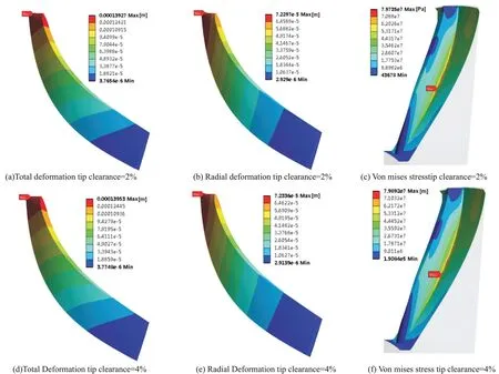

Fig.19 Finite element analysis results for the blade with optimal NACA tip profile
3) The finite element analysis results illustrates that the maximum total deformation and equivalent stress of the rotor with optimal NACA thickness distribution meet the size requirement of blade tip clearance and the tensile yield strength of aluminum alloy.
杂志排行

风机技术的其它文章
- Multi-objective Optimization of a Fan Airfoil Adaptive for the Inlet Distortion*
- Investigation on the Helium-foil of Highly Loaded Helium Compressor*
- The Effect of Compressibility in Computing Noise Which Induced at a Cavitating Device
- Gurney襟翼在离心压缩机叶轮上的数值研究*
- 吸油烟机多叶离心风机的优化与改进
- Effects of S-shaped Duct on Fan Blade Vibration