Numerical Simulation of Unsteady Flow of Reentry Capsule
2019-05-15MAYuanhongSHIXiaotianLVMengSHENQing
MA Yuanhong, SHI Xiaotian, LV Meng, SHEN Qing
China Academy of Aerospace Aerodynamics, Beijing 100074
Abstract: As a main tool for the lunar exploration and Mars landing project, the reentry capsule is responsible for the transportation of personnel and supplies, and it is very important to ensure its safety. The complex flow field caused by the shape of the large blunt cone makes it unstable in transonic and supersonic flight, so its dynamic characteristics need to be analyzed. This paper analyzes the dynamic characteristics of the reentry capsule by computational fluid dynamics(CFD) numerical simulation. The pitching combined dynamic derivative was obtained by simulation of forced pitching oscillation of the flight vehicle using the rigid dynamic grid; the time difference derivative was obtained by simulation of plunging of the flight vehicle using the rigid dynamic grid, too. The direct dynamic derivative was gained by negating the plunging derivative from sum. This paper simulates the pitching and plunging motion of NACA0012 air foil and hypersonic ballistic shape (HBS). The results of the simulation are consistent with the references. The Mars exploration rover entry capsule was simulated and analyzed to ensure a basis for the aerodynamic design and control of the reentry capsule.
Key words: CFD, unsteady flow, reentry capsule, dynamic characteristic
1 INTRODUCTION
With the development of lunar exploration and Mars landing projects in China, the reentry capsule, as a major tool in the space to Earth transportation system, undertakes important personnel and material transportation tasks. So, guaranteeing its safety is very crucial. Considering the requirement for thermal protection, the reentry capsule usually adopts a large blunt nosed inverted cone shape. However, the dynamic instability in pitching or pitching-yawing will occur during its passage at subsonic, transonic and even supersonic velocities. It is easy to enter a self-excited vibration state in the form of limit cycle after being disturbed by external disturbances[1]. Therefore, it is necessary to discuss the dynamic characteristics of the reentry capsule.
The complex flow field caused by the large blunt nosed inverted cone shape of the reentry capsule is the main reason for its dynamic instability at transonic and even supersonic velocities.Teramoto[2]used fine grids to simulate the flow field of the reentry capsule, trying to establish the influence of the structure of the flow field behind the reentry capsule on its dynamic stability.The numerical results showed that the dynamic instability of the reentry capsule was caused by the phase delay of pressure at the base. The research considered that the dynamic instability of the reentry capsule was caused by the phase delay of pressure at the base and the feedback of the flow field behind the reentry capsule, as Figure 1 shows.
Aerodynamic stability parameters of an aircraft are mainly characterized by dynamic stability derivatives. They are the derivatives of six aerodynamic coefficients of aircraft, including three force coefficients and three moment coefficients, which are important for aircraft design and dynamic stability analysis[3].In this paper, NACA0012 airfoil and HBS were selected to verify forced pitching and plunging motion. The Mars exploration rover entry capsule (MEREC) was selected to simulate and analyze its dynamic characteristics, providing a basis for aerodynamic design and control of the reentry capsule.
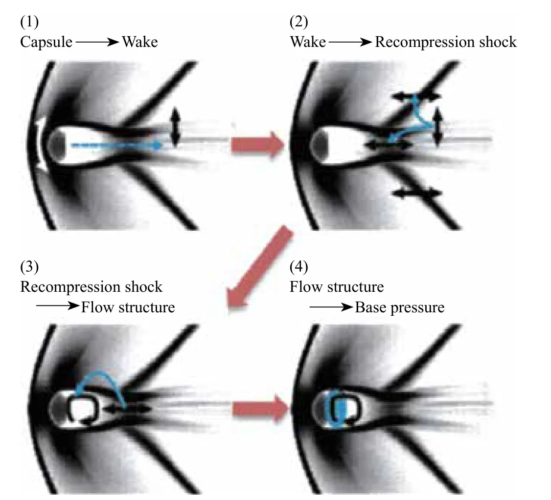
Figure 1 The feedback of the flow field behind the reentry capsule
2 NUMERICAL METHODS
2.1 N-S Equations
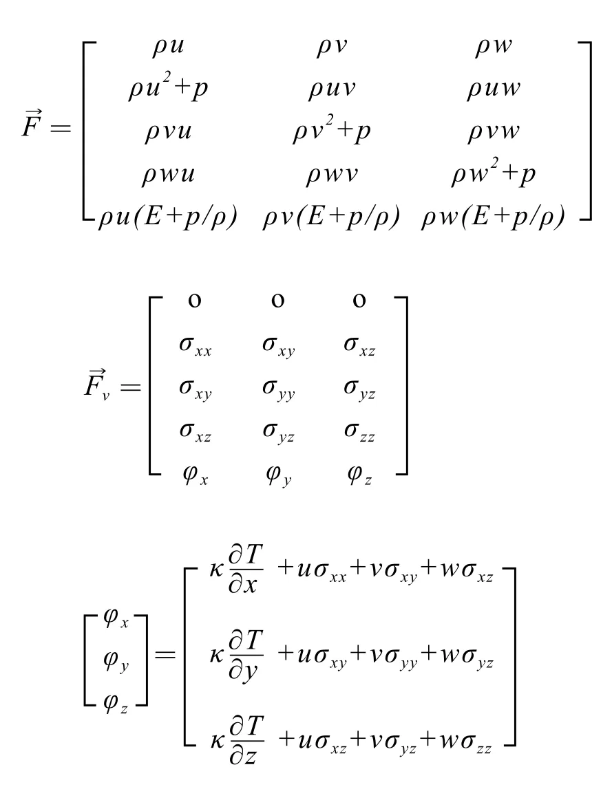
The three-dimensional compressible integral N-S equation can be expressed as:

2.2 Numerical Methods of Combined Derivative
For forced pitching oscillation with a single degree of freedom, the simplified harmonic oscillation (dimensionless) is given as follows:

where α0is initial angle of attack, αmis amplitude, k=ωLref/ 2V∞is reduction frequency.
By using the integral method, the solution formula of combined derivative is:

2.3 Numerical Methods of the Time Difference Derivative
The sinusoidal motion of a forced aircraft is governed by the following law:

where zmis the amplitude of plunging motion.
Similarly, the integral method can be used to obtain the formula for calculating the time difference derivative of small-amplitude plunging motion:

3 NUMERICAL SIMULATION RESULTS AND ANALYSIS
3.1 NACA0012 Airfoil Pitching Motion Numerical Simulation
The NACA0012 airfoil small-amplitude pitching motion test[3]reported in AGARD-R-702 is widely used in pitching motion dynamic tests and CFD dynamic calculation verifications.In this paper, the same flow conditions as the experiments are adopted:

Figures 2 and 3 are the hysteresis curves of lift coefficients and pitching moment coefficients with angles of attack. It can be seen that the calculated results are close to the experimental results,which shows that the simulation results in this paper are reliable.
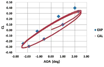
Figure 2 Lift coefficients varying with angles of attack comparing to experimental results
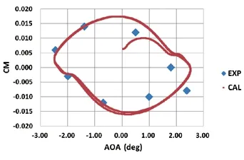
Figure 3 Pitching moment coefficients varying with angles of attack comparing to experimental results
3.2 NACA0012 Airfoil Plunging Motion Numerical Simulation
Plunging motion of NACA0012 airfoil is an example in CFD++ Help Manual[4]. The same flow conditions are adopted:

Amplitude is 3.21 m, f = 0.2653 Hz. Plunging motion is in accordance with sinusoidal law. Figures 4 and 5 are the curves of normal force coefficients and pitching moment coefficients.Comparing the results calculated in this paper and CFD++, it can be seen that the difference between them is small, which shows that the simulation of plunging motion in this paper is reliable.
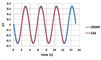
Figure 4 Normal force coefficients varying with time
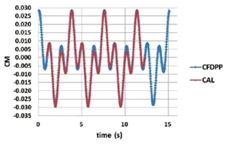
Figure 5 Pitching moment coefficients varying with time
3.3 HBS Motion Numerical Simulation
HBS is a hypersonic ballistic model with a hemispherical cylinder and two expanded skirts. Its dynamic characteristics are tested accurately and are widely used to verify the dynamic derivatives method. The configuration and grids are shown in Figure 6.
The calculated conditions areMa=6.85,α0=0°, 5°, 10°, 15°, 20°, k=0.01, αm=1°, amplitude of pitching plunging is 0.03 m.
From Figures 7 to 9, it can be seen that the calculated results are in great agreement with the reference experiments and calculations,which shows that the method of calculating dynamic derivatives in this paper is also reliable.
3.4 MEREC Pitching Motion Numerical Simulation
To verify the rationality and accuracy of the numerical calculation method, MEREC is selected for numerical verification. The MEREC configuration is shown in Figure 10.
The computational results of forced vibration and their comparison with those of reference are shown in Figure 11. In the reference, the ballistic target launch test model was used. The flight velocities and attitudes of the model were recorded by a series of cameras, and then the dynamic derivatives were extracted from the recorded data. Because the model in the test was powerless, there was a difference between the launch Mach number of the model and the final Mach number in the actual flight process,so it is only used for reference data here. It can be seen from Figure 11 that positive dynamic derivatives appear in the case of small angle of attack (AOA < 10) at Mach numberMa=1.5,Ma=2.5, which indicates that the state belongs in the dynamic instability region. At Mach numberMa=3.5, the dynamic derivatives of the shape are less than 0, indicating that the shape is dynamically stable. This is consistent with the results in the reference.
4 CONCLUSIONS
In this paper, NACA0012 airfoil and HBS are selected to validate forced pitching motion and plunging motion. MEREC is selected for the numerical simulation. It's dynamic instability in the case of small angel of attack atMa=1.5,Ma=2.5.
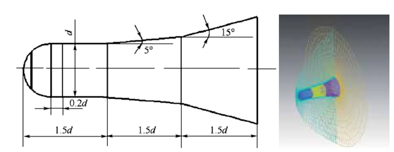
Figure 6 The configuration and grids of HBS
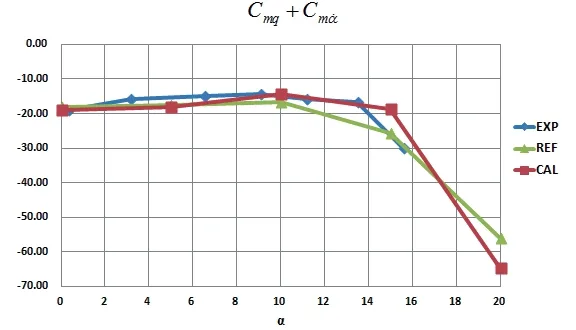
Figure 7 Calculated combined pitching dynamic derivatives of HBS compared to references
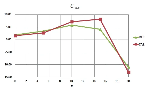
Figure 8 Calculated time difference pitching dynamic derivatives of HBS compared to reference
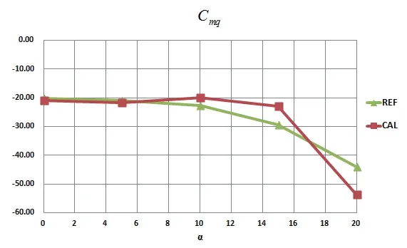
Figure 9 Calculated direct pitching dynamic derivatives of HBS compared to reference
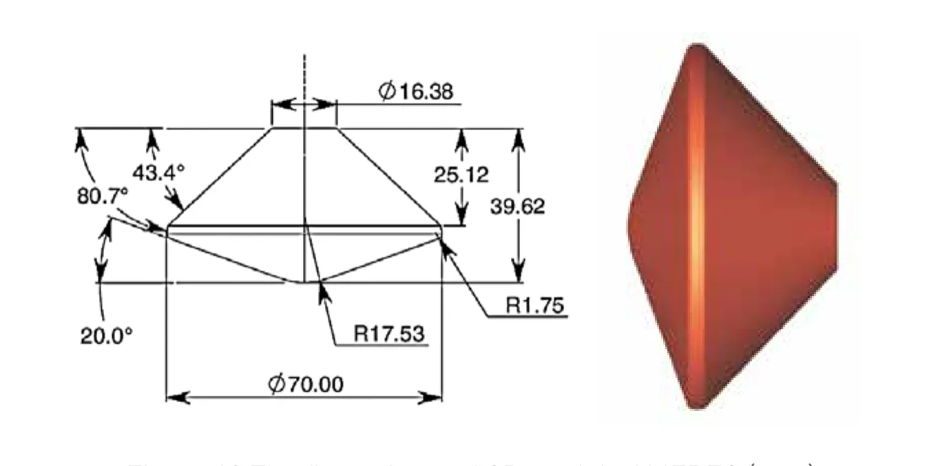
Figure 10 The figuration and 3D model of MEREC (mm)
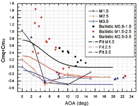
Figure 11 Numerical simulated results of forced motion compared to the reference
The method developed in this paper could be used to calculate and analyze the dynamic characteristics of the reentry capsule, and provide technical support for the aerodynamic design and control system of the reentry capsule.
杂志排行
Aerospace China的其它文章
- Application of Genetic Algorithm in Estimation of Gyro Drift Error Model
- Analysis and Solution of Multipath Effect on Wireless Communications of Launch Vehicle
- CFOSAT-1 Realizes First Joint Observation of Sea Wind and Waves
- Application Advantages of Staring Area Imaging Technology (SAIT) for Microsatellites
- Analysis of China's Nano andMicrosatellite Industry Development
- XUE Huifeng Attended the IAA Spring Meetings
