Efficiency optimized fuel supply strategy of aircraft engine based on air-fuel ratio control
2019-02-27YixunWANGYnSHIMolinCAIWeiqingXUQihuiYU
Yixun WANG,Yn SHI,*,Molin CAI,Weiqing XU,Qihui YU
aSchool of Automation Science and Electrical Engineering,Beihang University,Beijing 100083,China
bSchool of Mechanical Engineering,Inner Mongolia University of Science&Technology,Baotou 014000,China
Abstract Accurate fuel injection control of aircraft engine can optimize the energy efficiency of UAV power system while meeting the propeller speed requirement.Traditional injection control method such as open-loop calibration causes instability of fuel supply which brings the risk of power loss of UAV.Considering that the closed-loop control of AFR can ensure a stable fuel feeding,this paper proposes an AFR control based fuel supply strategy in order to improve the efficiency of fuel-powered UAV while obtaining the required engine speed.According to the optimum fuel injection results,we implement fuzzy-PID method to control the set AFR in different situations.Through simulation and experiment studies,the results indicate that,to begin with,the calibrated mathematical model of the aircraft engine is effective.Next,this fuel supply strategy based on AFR control can normally realize the engine speed regulation,and the applied control algorithm can eliminate the overshoot of AFR throughout all the working progress.What is more,the fuel supply strategy can averagely shorten the response time of the engine speed by about two seconds.In addition,compared with the open-loop calibration,in this work the power efficiency is improved by 9%to 33%.Last but not the least,the endurance can be improved by 30 min with a normal engine speed.This paper can be a reference for the optimization of UAV aircraft engine.
KEYWORDS AFR control;Aircraft engines;Efficiency optimization;Fuel supply strategy;Simulation and experiments
1.Introduction
Currently,fuel-powered unmanned aerial vehicle(UAV)has been widely applied in transportation,agriculture and plant protection because of the advantages of small size,low weight,simple structure,and simple operation.1However,at present,cruising duration of a typical fuel-powered civilian UAV is less than one hour,which is not suitable for long-duration missions.Donateo et al.calculated the flight endurance using fuel batteries,and this method will increase the load on the fuelpowered engine.2Cestino summarized that the basic long dur-ance for UAV should be more than 2 hours.3Therefore,scientists and engineers have paid attention to fuel supply optimal control technology of fuel-powered UAVs in order to prolong the cruising duration.Zhou et al.evaluated the efficacy of a fuel-powered unmanned helicopter of middle size for agriculture spray through comprehensively adjusting the flight parameters.4Bogarra studied the optimization methods for gasoline direct injection engines,and compared them with the spark ignition engine technologies.5Therefore,research on fuel-powered vehicles is still a hot topic nowadays.
Upper bound of the lift force limits the fuel capacity of UAV,and then engine fuel consumption efficiency directly affects the cruising duration.Latest studies of the aircraft engine have mainly focused on the fuel control logic.Hooper et al.carried out tests to examine the minimum engine starting temperature by experimentally testing the engine speed and power.6What is more,they conducted computer modelling of the engine system by experimental research in order to reduce the specific fuel consumption.7However,their confronting problems are starting difficulty and power plunge because it is hard to set the optimal injector pulse width.Lu analyzed the output power and lift force of a two-stoke aircraft engine through experiments,but he ignored the injected fuel control and brought the risk of engine outage because of insufficient fuel supply.8Bayındır et al.obtained the variations in different gas emissions with different engine power.9In addition,Dubey and Rajesh studied the effect of the mixed fuel on the engine characteristics without fuel injection control.10However,their studies are still short of fuel control analysis for a fuel-powered UAV engine.
In order to optimize the combination property of the fuelpowered UAV,the power efficiency,engine speed and other indicators should be synthetically considered,and the characteristics can be determined by the engine control strategy.Das et al.applied a new dual injection strategy to modify a single cylinder direct injection diesel engine to run on homogenous combustion mode.11They analyzed the effect of the injection time around a crank angle range.Chen et al.improved the combustion efficiency of direct injection diesel engine by adjusting the injection strategy,and the key injection parameters were also the fuel injection time and angle.12Costa et al.increased the energy efficiency of a gasoline direct injection engine through optimizing the synchronization strategies of the fuel injection.13They make the mixture characteristics properly adapted to the specific working condition in order to increase the engine energy efficiency.Loop-up table is always used in the industrial control field of engine calibration.Grasreiner et al.carried on virtual engine calibration based on phenomenological methods,and they obtained engine control maps.14Park et al.experimentally optimized a diesel engine,and they calibrated the landmarks of control points.15Therefore,loop-up map is the mainstream in the parameter setting of engine control unit.However,fuel injection without feedback adjustment will cause instability during the transition period of calibration status change because point-to-point calibration is not smooth enough.
Closed-loop control of air-fuel ratio(AFR)can ensure a stable fuel feeding.The AFR control system adjusts the injected fuel in real time according to the feedback parameters in order to make the AFR value maintained at stoichiometric value(generally is 14.7),which can keep the three-way catalyst working with the highest efficiency and control the harmful exhausts such as NOxand CO within an appropriate range.16-18Lately,advanced control methods have been implemented by researchers in the engine control.Choi and Hedrick applied observer-based sliding mode to control AFR stably with a closed loop.19A second-order sliding mode strategy was developed by Ebrahimi,and he eliminated the time delay effects by simulation.20Wu and Tafreshi combined the fuzzy and sliding-mode strategies,and they achieved high control robustness.21Based on Takagi-Sugeno model,Khiar et al.developed a fuzzy control strategy and improved the effectiveness by engine experiments.22Sardarmehni et al.used RBF network to perform a predictive control on internal combustion engine,and they improved the control characteristics with a smoother injected fuel flow.23In addition,neural network control on SI engine was proved to be of better robustness by Zhai et al.24Nevertheless,most of the control studies still stay in the theoretical stage.What is more,overcomplicated methods have problems of poor real time,and the relevant control values are hard to set.Researchers apply fuzzy mathematics theory and fuzzy inference to realize the optimization of PID parameters in the SI engine control.25-27Based on simulation studies,the researchers have obtained a stable control of AFR and speed of engine.However,there is still lack of experiment verification on the AFR control of UAV aircraft engine.
Traditional PID can hardly meet the control requirement of engine AFR because of the high nonlinearity of engine model.Recently,researchers have applied fuzzy mathematics theory to realize the optimization of PID parameters in the SI engine control.25,26Based on simulation studies,the researchers have obtained a stable control of AFR and speed of engine.
This paper proposes a new kind of fuel injection strategy for the aircraft engine which is based on flight working conditions.Distinguished from the previous works,this paper applies different AFR set values under different propeller rotating speeds in order to maximize the power efficiency as well as ensure adequate output power at the same time.Fuel pulse width signal is integrated into the mean value model in order to perform accurate control simulation and parameter optimization.In order to realize stable control under different working conditions,fuzzy-PID control method is implemented to achieve dynamic control target control.Engine control mathematical model is set up,and an aircraft engine test station is built to calibrate and verify the model.The optimum injection parameters are calculated,and based on the dynamic target values the control strategy results are obtained.In order to argument the effect of the AFR controlled fuel supply strategy,its control result is compared with strategy of fixed pulse width and open-loop controlled pulse width.
2.Methodology of model and experiment
2.1.Research object and modeling
A two-stroke fuel-powered engine with model of DLE170 is researched in this study,and main specifications of DLE170 engine are shown in Table 1.However,the application speed range of the aircraft engine is 3500 to 5500 r/min,so the experimental and simulation studies are required to confirm the engine performance.As shown in Table 1,1 inch is equal to 0.0254 m,and 1 cc is equal to 1 mL.
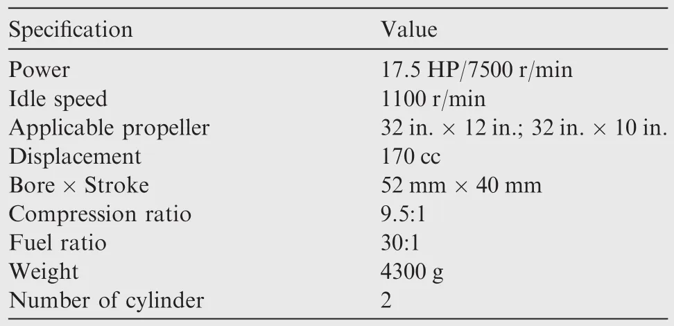
Table 1 Specifications of DLE170 engine.
Fuel supply device of the studied aircraft engine is modified from carburetor to electronic fuel injection system(EFI system)because EFI system is more flexible and can adapt intelligent control.The reason is that the traditional carburetor is purely mechanical and can hardly self-regulate according to the flight parameters.Therefore,when the intake air flow is changed,the intake fuel flow will be too much or too little,and that will cause inefficient burning.EFI system is controlled by electronic controller,and it can accurately calculate the fuel flow according to the gathered operating data.Through an accurately control strategy on the EFI,the aircraft engine can work more smoothly and economically.The parameters of the EFI system are shown in Table 2 where both the inject fuel angle and spark advance angle are 25 degrees because the compression ratio and regular speed of DLE170 engine are relatively high,which lead to little effect of the advance angle.
Modeling of the aircraft engine should mainly focus on the effect of fuel-injection quantity on output engine characteristics.The inject fuel mass flow can be obtained by dynamically analyzing the EFI working process.The magnetic flux formulas when a fuel injector is electrified and not electrified are as follows:

whereU0is the source voltage(V),Rcmeans resistance of coil loop(Ω),iis the loop current(A),Nis the number of the coil,Φbis total magnetic circuit(Wb),tmeans the time,andR0means resistance for protection(Ω).

Table 2 Parameters of EFI system.
The electromagnetic force on the needle valve when the coil is electrified is as follows:
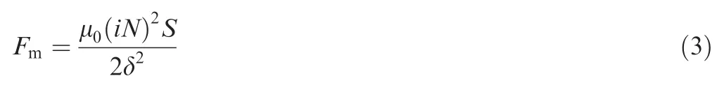
whereFmis electromagnetic force(N),μ0means vacuum permeability,Sis the cross-section of the air gap(mm2),and δ means length of working air gap(mm).
The kinetic equations of the magnetic needle valve are as follows:
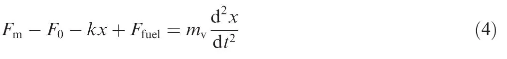
whereF0is the initial tension of spring(N),kmeans spring stiffness(N/mm),xis the needle valve displacement(mm),Ffuelis fuel pressure(N),andmvmeans mass of the needle valve(kg).
When the needle valve is opened,a high-pressure fuel releases,generating a fuel flow.The equation of the fuel flow is as follows:

wheremfiis the mass of inject fuel(kg),μnmeans injector flow coefficient,Snis the hole area of the injector(mm2),gmeans acceleration of gravity(m/s2),ρfis density of the fuel(kg/m3),Piis inject fuel pressure(Pa),Pmis the engine manifold air pressure(Pa),andtdmeans open time of the injector(ms).Mean value model theory has been developed for years.28,29
Compared with a traditional thermodynamics model,the mean value model is simple and practical,and various research studies have applied the theory to the engine control.Fuel vapor and fuel film equations are as follows:

wheremfvis the mass of fuel vapor into the crankcase(kg),mffis the mass flow of the fuel film into the crank case(kg),τfmeans film evaporation coefficient,andmfis whole fuel mass into the crankcase(kg).
Air mass flow equations in the engine manifold are

wheremmanis air mass in the engine manifold(kg),matis air mass through the throttle plate(kg),mapis air mass into the crankcase(kg),nmeans engine speed(rpm),Vdis cylinder displacement(cc),ρmanis air density in the engine manifold(kg/m3),and ηvolis working volume coefficient.
Equation of air pressure in manifold can be written as follows:
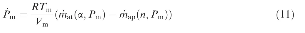
whereRis gas constant factor,and α is throttle opening degree(degree).In the engine manifold,Vmis the volume of the engine manifold(mm3),andTmis the air temperature(K).
Equation of crank shaft and loads on the engine are
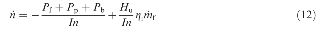
wherePfis friction power(W)related with engine speedn,Ppis pumping loss power(W)related with engine speednand manifold pressurePman,Pbis engine load power(W),Huis gas calorific value which is 45,000 kJ/kg,fuel energy transform efficiency is expressed as ηi,andIis inertia of the engine(kg mm2).
UAV propeller can be divided into elements according to blade element theory.Lift and drag forces on the propeller element are as follows:
whereLproandDproare lift and drag forces(N)respectively,CLandCDare propeller lift and drag force coefficients respectively,ρais atmospheric density(kg/m3),v is line speed relative to the air(m/s),andAΔris propeller element surface area(m2).
Tensile and lift forces can be calculated as follows:

where β is angle between the air flow direction and the horizontal line(degree),andTproandQproare tensile force and rotating resistance(N)respectively.
And the propeller torque is

whereMRis propeller torque(N·m),andrprois UAV propeller radius(m).
Load power of the engine can be obtained as follows:

Moreover,UAV propeller of type NACA 0012 airfoil is chosen,and we set the propeller design values and drag force coefficients according to the standard of U.S.
AFR of the aero engine can be calculated according to Eq.(19):

where λ stands for AFR.What is more,propagation of the engine cycle and sensor measurement delays are considered,and length of the delay timetdis shown by

2.2.Test setup
Efficiency analysis of the aircraft engine requires test of output power.Common studies always implement power dynamometer on engine.30,31However,the traditional dynamometer can hardly simulate the actual UAV operating condition because external load of the aircraft engine comes from the drag force of the propeller which is different from the automobile friction.So in this study,as shown in Fig.1,we design an integrated test station which can measure engine speed,output power and AFR.In this test station,engine output shaft is connected to a torque sensor,and the sensor can measure the output engine speed,too.The other side of the torque sensor is connected to a wooden propeller of size 32 in.×12 in.Coupling joints of both sides are made of aluminum.The capacitor discharge ignition(CDI)is directly connected to the two engine ignition plugs.The CDI can be controlled by the engine control unit(ECU),and ECU can control the ignition angle.The fuel supply pressure of EFI is kept at 0.35 MPa.ECU collects the real-time signals of speed,torque,AFR and throttle opening degree,and sets up the inject fuel width and the spark advance angle.Fig.2 is the photograph of the aircraft engine test station.
2.3.Model calibration and verification

Fig.1 Schematic diagram of test station.

Fig.2 Aircraft engine test station.
In order to make the engine model match the experimental results,this section dynamically calibrates all the model parameters.The model is implemented in a MATLAB environment and all the parameters should be specified.All the parameters can be divided into three kinds:(a)known parameters such as nozzle diameter of the injector,size of the propeller,cylinder number and size,and compression ratio which are available from engine manufacturers;(b)arbitrarily set parameters. These parameters are always nondimensionally expressed as a function of some known parameters,and their values are always obtained from the engine experiments,for example,diameters of inlet and exhaust manifolds;(c)uncertain parameters.These parameters,such as resistance/loss and contraction factor in the inlet and outlet valves,are always intrinsic to the mean value model and needed to simulate a present phenomenon of the engine.Through estimations of several uncertain model parameters including air intake efficiency, film coefficient,and load efficiency,we calibrate the mean value model in order to match the performance of the aircraft engine.
Mean value model of the engine mainly includes fuel vapor and fuel film,air mass flow and model of crank shaft and loads.According to the three models,the uncertain parameters which need to be calibrated in the engine mean value model can be classified into three types:(a)ratio of the fuel film partXand film evaporation coefficient τf.Xand τfare calibrated in pairs by least squares fit method;(b)relationship between the intake air mass flow and the opening degree α.Eq.(11)only reflects the basic calculation principle of the intake air mass flow.However,according to the experience from a series of experiments,when fuel control pulse width and engine speed are definite,the throttle opening degree and the output AFR basically correspond.In order to improve the accuracy as much as possible,the engine intake air mass flow and throttle opening degree are settled to a cubic equation.The fitting parameters are calibrated by least squares fit method according to the experiment results;(c)fuel energy transfer efficiency,friction and loss power.These parameters are directly related to the output power of the engine.According to the engine experiment,we can get the relationship among the engine speed,air flow rate and the throttle opening degree.The parameters that need to be calibrated are nonrepresentational,and they can hardly be measured by tests.In Eq.(12),the engine can be simplified to a first-order equation.According to the dynamic principle,the parameters can be regulated in order to match the experimental results.
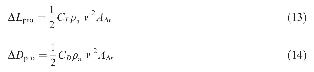
In order to research the effect of AFR control on the output characteristics of the aircraft engine,we design the AFR experiments to verify the mathematical model above.In the experiment studies,we settle the fuel pulse width according to the signals of engine speed and throttle opening degree in order to keep the AFR as stable as possible.Then we appropriately adjust the throttle by slowly increasing and reducing the opening degree meanwhile making sure that the output engine speed and torque are steady.Then we get the experimental results of the engine speed,power and AFR.According to the settled parameters,we simulate the experiment process.In the simulation model,the input throttle opening degree is the same with the experiment setting.The simulation results are shown as Fig.3(a)-(c).From these figures,results of the experiments and simulations are consistent with each other,and then the calibrated engine model is verified.According to Fig.3(a)and(b),in general,the tendency of output power follows that of engine speed.Nonetheless the curve of output power has apparent overshoot at the time when the engine speed stops increasing and maintains steady.The same phenomenon occurs when the engine speed stops decreasing.In Fig.3(c),AFR is kept relatively steady expect when the speed increases or decreases because when the throttle opens larger,the engine speed will increase.In our inject fuel control logic,the pulse width changes with the engine speed,so the fuel flow will also have a rise,and then the engine will not power down for lack of injected fuel.The inertia of engine shaft leads to the overshoot of output torque,which is consistent with the reality.
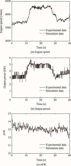
Fig.3 Experiment and simulation comparison curves of engine speed,output power and AFR.
3.Fuel supply control strategy
3.1.Optimum fuel injection
Power efficiency is one of the most important characteristics of the aircraft engine.Engine with higher power efficiency can exploit its potential performance,save fuel and then prolong the UAV flight endurance.Power efficiency of the aircraft engine ηecan be calculated by the following equation:

wherePoutis the system output power(W),Pinis the system output power(W),andToutis the output torque of the engine(N·m).
In the situations of different engine speeds,throttle degrees and so on,there is always an optimum fuel injection option that can make the power efficiency the highest.Aircraft engine integrated experiments can hardly include all the working condition because the experimental process is complicated and some extreme operating conditions are irrealizable.So as far as possible,we implement the verified mathematical model to simulate all the working conditions.
In the real application,fuel supply parameters of the engine are calibrated by testing the optimal testing points of different working conditions.For the applicators,they directly adjust the throttle opening degrees to control the engine speed.Through the engine experiments,when we set the fuel pulse width constant,the engine will work normally with a rotating speed range.However,when the throttle degree is small,the injected fuel flow will be relatively high,and engine will work under the tending rich-fuel condition.That will lead to a waste of fuel because the engine is not fully burning gasoline with combustion of rich-fuel.Moreover,when the corresponding injected fuel flow is relatively low,output power of the aircraft engine will be insufficient,which will result in the risk of speed droop or even engine outage.In this section,we aim to find the optimum fuel injection parameter in order to guarantee both working safety and fuel economy.
In order to find the optimum fuel injection pulse width,we scan the injection pulse width from 4.0 to 7.0 ms in the engine fuel control system,and we scan the throttle opening degree from 30 to 70 degrees according to the real situation.Then we get the efficiency illustration as shown in Fig.4.

Fig.4 Efficiency of different fuel injection pulse width.
From Fig.4,we can get the optimum fuel injection results.The general power efficiency of two-stroke engine used on automobile is 10%to 20%.UAV working torque load comes from the drag force on the propeller which changes with the variation of the engine speed.Besides,the used engine speed range is much higher than that of the ground vehicle.Above all,the aircraft engine exhausts emission very quickly,which can take away some unburned fuel.So,as for UAV,the output power is low and the fuel consumption is high,which can explain the reason why the aircraft engine power efficiency is lower than the common indicator.In this figure,there are some points that need to explain:(a)break point.For example,when the injection pulse width is 4.0 ms,we can see from the figure that the corresponding line only extends until the throttle opening degree is 35 degrees.That is because if the throttle opening degree is set higher,the air-fuel ratio will be over high,and the engine will shut down or work at idle speed.Similarly,when the throttle opening degree is 40 degrees,45 degrees or 55 degrees,there are break points;(b)power down point.In this figure,when the throttle opening degree is 50 degrees and the pulse width is 4.2 ms,there is a power down point.On the same line,power down point's next point always has a lower power or is a break point,which means that this point is at the risk of making the engine power down.For those two kinds of points,we adopt a conservative approach:we accept the nearest points as the control parameter.
Fig.5 is the AFR from the calculation results.When the control points are determined,the corresponding AFR values can be obtained.Furthermore,we can get values of the corresponding output engine speed to make sure that our control can meet the requirement of the UAV.The preliminary control parameters are determinate as shown in Table 3.Based on the parameters,we settle the open-loop control strategy of the engine,and then get the efficiency and AFR results as shown in Fig.6(a)and(b).

Fig.5 AFR of different fuel injection pulse width.

Table 3 Control parameter of fuel supply system.
Fig.6 Efficiency and AFR comparison curves.
In Fig.6(a),the throttle opening degree is enlarged as time increases(31-40 s is 40 degrees,41-50 s is 45 degrees,and so on).We can see that the efficiency with a control strategy is obviously higher than that of an open loop control.So the optimum fuel injection is effective.It can be seen from Fig.6(b)that the AFR is basically controlled at the set values in Table 3.However,during the time when throttle opening degree rises,the response signal of the controlled air-fuel ratio is with an overshoot.Through the aircraft engine experiment,we get a conclusion that when the inject fuel flow is not steadily kept,the engine speed and power will sharply change.So the AFR control is also important for the fuel supply system.While considering the power efficiency,we should guarantee the control effect of the controlled engine speed and the AFR.
3.2.AFR control method
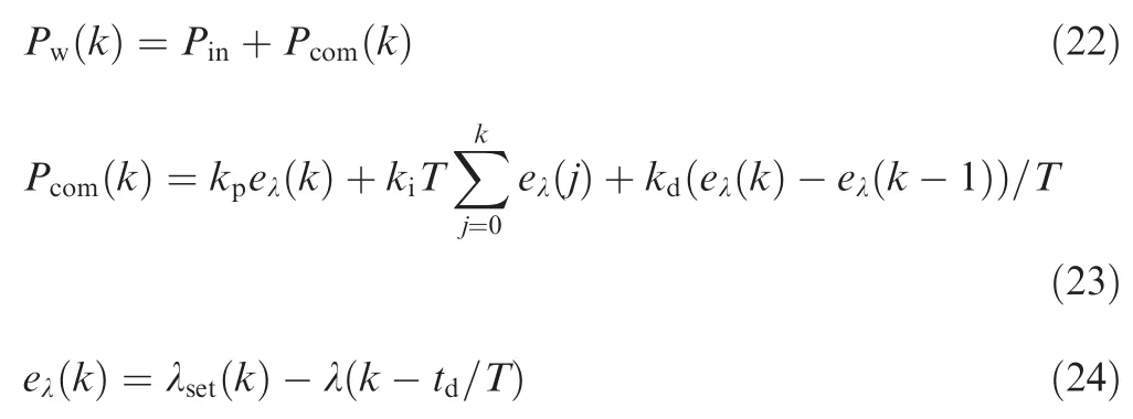
As shown in Fig.7,we apply fuzzy-PID algorithm to control the AFR.λsetis the settled target AFR which is set according to Table 3.Fuel pulse widthPw(ms)is directly inputted in the dynamic fuel model of the engine,andPcom(ms)is the fuel pulse width compensation value obtained by the feedback closed-loop control.The three PID parameters(kp,ki,kd)are adjusted in real time by a fuzzy controller,and inputs of the fuzzy rules are AFR error(eλ),its change(Δeλ),throttle opening degree(α)and its change(Δα).
AFR is directly controlled byPw,andPwcan be calculated by the following equations:
In this paper,the fuzzy rules are self-adjusted according to the fuzzy relations:

where∈[0,3]and they are the fuzzy outputs.kpminmeans the minimum value ofkp,andkpmaxmeans the maximum value.kimin,kimax,kdminandkdmaxstand for the same meaning.
As shown in Table 4,since there are too many fuzzy rules,we select one of the tables as shown in this paper.It is the fuzzy rule ofk′pwhen α and Δα are positive.Compared with artificial neural network,multi-order sliding and other advanced algorithms,and sliding mode,fuzzy-PID method is relatively easy to apply in the practice.The working process of AFR control using fuzzy-PID is shown in Fig.8.Here we simulate the real application:ECU gathers the sample values of the throttle opening degree and AFR.Change rates of the signal are calculated by subtracting the current and previous signals.Throttle degree and its change rate can be considered as the basis of the fuzzy rules.AFR error and its change rate are then fuzzily processed by embedding fuzzy rules into the control system.Parameters of PID control are timely calculated,and the error of AFR will be minimized during the engine working process.
3.3.Results of control strategy
We implement the AFR control algorithm in the fuel supply strategy,and result is compared with that of the preliminary control without AFR control method.As shown in Fig.9,when we compare the two methods with and without AFR control algorithm,and use the fuzzy-PID control method,overshoots of the AFR line disappear.In addition,the AFR control response time is averagely shortened by 2-3 s.
We also obtain the engine speed control results of the two methods as shown in Fig.10.It can be concluded that,when we implement the closed-loop control of AFR to the aircraft engine,the engine speed can be controlled normally.What is more,according to the figure,control strategy of this paper can shorten the response time of the speed control by about two seconds.That is because when we use the AFR control algorithm,the AFR is controlled much better according to the settled AFR value.According to the engine characteristics,the engine speed,AFR and engine throttle opening degree are one to-one corresponding relations.Therefore,when the output AFR is controlled well,the engine speed will be controlled with a rapid response.

Fig.7 Efficiency and AFR comparison curves.

Table 4 Fuzzy rule of k'pwhen α and Δα are positive.

Fig.8 Application procedure of AFR control based on fuzzy-PID.
As shown in Fig.11,through the AFR controlled strategy,optimization of the efficiency is almost the same with the preliminary strategy with pulse width open-loop control.Compared with the original method of using fixed inject fuel pulse width,when the speed is around 6500,7300 and 7600 r/min,the power efficiency is improved by about 33%,15%and 8.7%respectively.
In the application of the aircraft engine,the engine proposes the rotation power for the propeller as a certain speed.Range of the most used speeds is 6500-7500 r/min.When the engine speed is kept still,the UAV can overcome its own gravity,and then the rotor-UAV flight algorithm can be applied.If we assume that the factors,including the UAV flight stationary,the flight weather and environment,the use time of the engine and so on,are kept consistent,we can study the influence of the efficiency on the UAV endurance.
The endurance of a UAV with a fuel-powered engine can be calculated as

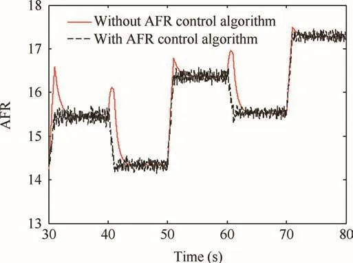
Fig.9 AFR comparison curves with and without control algorithm.

Fig.10 Engine speed curves with and without AFR control algorithm.

Fig.11 Efficiency curves of original,preliminary and closed loop control.
whereTeis the endurance time of the UAV,andVtis the capacity of the fuel carried by UAV.It can be seen that the key factor of the time endurance is the mass flow of the injected fuel.The fuel capacity of DZ310 Plant protection UAV is about 3-4 L,and ρfis about 0.737 kg/L.Then we can get the results of UAV flight endurance as shown in Table 5.In Table 5,the engine efficiency and endurance are calculated under different working speeds.It can be seen that when the engine speed is a normal value(6500 r/min),and UAV works continuously for a while,the endurance can be improved from about 1h30min to 2 h.If the translational velocity of the UAV is 60 km/h,haul distance of the UAV can be prolonged by about 30 km.However,when the engine speed is higher than 7000 r/min,for example,7300 r/min and 7600 r/min,the engine endurance will not be obviously prolonged.That is because the engine efficiency will not be greatly improved at those speeds.So,following the increase of the power efficiency,the UAV endurance will be prolonged.
4.Conclusions
This paper studies the relationship of aircraft engine fuel supply,AFR and power efficiency,and a new fuel supply strategy is proposed based on the UAV flight working conditions.
(1)This paper settles different AFR control targets under different UAV working conditions,and puts forward a method for settling the optimal AFR targets based on aircraft engine model.According to the power down characteristic of the aircraft engine,we define the power down points and break points and accept the nearest points as the AFR control target.The control strategy based on the AFR targets can improve the efficiency from about 5%to 25%.
(2)Fuzzy-PID control method is applied in the dynamic AFR control target,where we integrate the discrete AFR targets in the fuzzy rules.The fuzzy-PID control based strategy can normally realize the engine speed regulation,and the applied control method can eliminate the overshoot of AFR throughout all the working progress.Furthermore,response time of the engine speed can be averagely shortened by about two seconds,and the power efficiency can be improved by 33%when the engine speed is 6500 r/min;when the engine speed is controlled around 7300 r/min,the efficiency can be optimized by about 15%.
(3)Endurance of a UAV type is predicted.When the engine speed is at normal level,the endurance can be improved by 30 min when using this strategy,which can prolong the haul distance of UAV by about 30 km.

Table 5 Endurance comparison.
Acknowledgements
This study is financially supported by the National Natural Science Foundation of China(No.51605013)and the Pneumatic and Thermodynamic Energy Storage and Supply Beijing Key Laboratory.
Appendix A.Supplementary material
Supplementary data to this article can be found online at https://doi.org/10.1016/j.cja.2018.10.002.
杂志排行

CHINESE JOURNAL OF AERONAUTICS的其它文章
- Guide for Authors
- Special Issue call for papers: Emerging Technologies of Unmanned Aerial Vehicles
- Identification of the state-space model and payload mass parameter of a flexible space manipulator using a recursive subspace tracking method
- Effects of splined shaft bending rigidity on cylinder tilt behaviour for high-speed electrohydrostatic actuator pumps
- Event-triggered adaptive control for attitude tracking of spacecraft
- Reliable flight performance assessment of multirotor based on interacting multiple model particle filter and health degree