Numerical study on flow control of ship airwake and rotor airload during helicopter shipboard landing
2019-02-27YongjieSHIXingHEYiXUGuohuXU
Yongjie SHI,Xing HE,Yi XU,Guohu XU
aNational Key Laboratory of Rotorcraft Aeromechanics,Nanjing University of Aeronautics and Astronautics,Nanjing 210016,China
bShanghai Institute of Electro-Mechanical Engineering,Shanghai 200233,China
Abstract A numerical study on flow control of ship airwake during shipboard landing is carried out to address the effect of flow control devices on helicopter rotor airload.The in-house Reynolds Averaged Navier-Stokes(RANS)based solver Rotorcraft AeroDynamics and Aeroacoustics Solver(RADAS),with combination of momentum source approach is employed to conduct the helicopter shipboard landing simulation.The control effects of three aerodynamic modifications of ship superstructure,i.e.ramp,notch and flap,in different Wind-Over-Deck(WOD)conditions are discussed.From the steady simulation results,the effect of spatial variation of ship airwake on rotor airloads is concluded.The aerodynamic modifications reduce the strength of shedding vortex and increase rotor normal force through delaying and relieving flow separation,and therefore are beneficial to alleviate the limitation of control inputs.By contrast,the perturbation of unsteady ship airwake can cause the serious oscillation of rotor forces during shipboard landing.The unsteady simulations show that the turbulence intensity of ship airwake and oscillatory rotor airloading,represented by Root-Mean-Square(RMS)loading,can be remarkably reduced by the ramp and notch modifications,while the flap modification has adverse effect.It means that flow control devices have large potential benefits to alleviate the pilot's workload and improve the shipboard landing safety,but they should be well designed to avoid the introduction of more vortex,which leads to increase in disturbance of flow field.
KEYWORDS Flow control;Helicopter;Rotor airload;Ship airwake;Shipboard landing
1.Introduction
The shipboard landing is one of the most dangerous and challenging tasks for the helicopter pilots.This is mainly due to both the random six-degree-freedom motions of ship and the disturbed shipwake caused by the bluff-body flow separation.1,2This shipwakeis characterized by the unstable recirculation zone,the separated shear layer and the mutual interaction with rotor wake.Its large gradient and unsteady characteristics have significant impacts on the stability and controllability of the helicopter operations.To improve the safety of helicopter shipboard landing,the flow control techniquecan beimplemented to alleviate the adverse effects of airwake by modifying the design of the ship superstructure.
Within the past several decades,extensive studies regarding the ship flow field in the vicinity of the flight deck have been conducted computationally and experimentally.The deep understanding about the flow structure,unsteady characteristics and parametric influence of the isolated ship airwake has been presented in Ref.3-9.However,these studies only focused on analysis of airwake.In 2015,Oruc et al.10investigated the rotor/ship flow field using the efficient momentum source approach for the development of a virtual dynamic interface simulation.The numerical simulation of coupling rotor/ship operational limitation was carried out by Crozon et al.11using steady actuator-disc method and unsteady rotor blade method,illustrating the importance of coupling effects on the wake and rotor in flow as helicopter moves closer to the ship.Additionally,several researchers have focused on the flow control of ship airwake.Czerwiec and Polsky12suggested that the application of the bow- flap could reduce the turbulence intensity over the bow landing spots.The study was conducted using a landing helicopter assault.Findlay and Ghee13conducted wind-tunnel experiments to investigate the effect of aerodynamic modifications to a Navy Destroyer on reducing the adverse effects of the airwake on helicopter operations in headwind condition.In the work of Greenwell and Barrett,14a dense screen,mounted on the sides and roof of the hangar and inclined rearwards was found to give the better performance.Shafer15investigated the active flow control means for ship wake.An improvement of flow field was achieved by using mass jet flow that injects through the hangar face.However,these studies just focused on the effect of flow control on the isolated ship flow field.In 2013,Kääriäet al.16conducted a wind-tunnel experiment to investigate the aerodynamic impact of ship superstructure modifications on helicopter operations.In his work,the potential benefits of aerodynamic modifications to ship airwake and unsteady rotor forces in the crosswind condition were stated.However,limited by laboratory condition,few discussions of flow control mechanism were presented in his study.
In this paper,a numerical study on flow control of ship airwake during shipboard landing is carried out to address the mechanisms for the impacts of the flow control devices on the helicopter rotor airload.Applying the coupling helicopter/-ship simulation method developed in Ref.17the steady simulations of coupling rotor/ship in conditions of different flow control devices are performed first,and the spatial variations of velocity and vortex field and their influence on rotor airload distribution is discussed in detail.Then,the unsteady simulations are conducted,and the research emphasis is placed on the impact of flow control technique on the turbulence intensity of ship airwake and rotor RMS forces and moments from the aspect of unsteady characteristics.Furthermore,the effectiveness of the flow control devices under different WOD conditions is described in this paper.
2.Numerical method
2.1.CFD solver
The in-house solver:Rotorcraft AeroDynamics and Aeroacoustics Solver(RADAS)is used to perform the numerical simulations of the coupling rotor/ship flow field.In RADAS-code,the three-dimensional,unsteady RANS equations are employed as the governing equations:

where W is the vector of conserved variables,F and FVare the convective and the viscous flux vectors,respectively.R represents source term.β is logical variable for rotor model.Vis the volume of gird,Sand n are the area and normal vector of grid surface.
The inviscid and viscous terms in Eq.(1)are computed using the upwind Roe scheme17and central difference,respectively.The dual-time stepping method is applied with the second order Lower-Upper Symmetric Gauss-Seidel(LU-SGS)scheme18to simulate the unsteady flow phenomenon.Twoequationk-ε turbulence model19is used for the RANS closure.
It is important to maintain the unsteady velocity components in the research of flow control for ship airwake.Actually,the capability of unsteady wake simulation strongly relates to the turbulence model used in RANS code.Fig.1 presents the time histories of streamwise velocity of LPD-17 ship model usingk-ε turbulence model and Shear Stress Transport(SST)k-ω turbulence model,respectively.The simulation is performed with a free-stream velocity of 15 m/s and 0°WOD angle.It is clear that the SSTk-ω turbulence model can capture the unsteady characteristics of ship airwake better.

Fig.1 Comparison of streamwise velocity using different turbulence models.
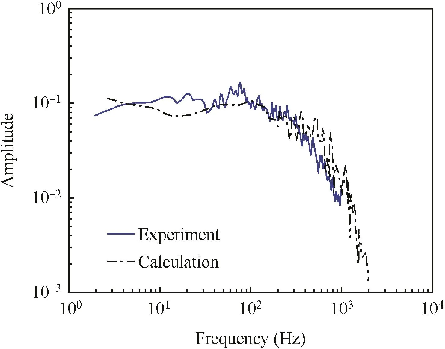
Fig.2 Spectra of streamwise velocity.
Moreover,Polsky has conducted a comparative study between SSTk-ω turbulence model and MILES(Monotone Integrated Large Eddy Simulation)method.The result also shows that the SSTk-ω turbulence model has the ability to capture the unsteady flow field characteristics,especially in the closed-loop pilot response frequency range.To demonstrate the effectiveness of SSTk-ω turbulence model further,spectral analysis is carried out for the unsteady flow characteristics of SFS2.Fig.2 shows the plot of Power Spectral Density(PSD)for the point location on 50%off-body plane over the flight deck.It can be seen that despite some discrepancy,the trend agrees well with the experiment data.
In general,unsteady RANS(URANS)based RADAS solver is able to conduct the comparative study of flow control for ship airwake and the effects of flow control methods on rotor loadings,despite it is insufficient to simulate unsteady characteristics more accurate than Detached Eddy simulation7and Large Eddy Simulation8solvers.
Two rotor models are included in RADAS solver.One is the unsteady model,where each rotor blade is covered by body- fitted grid and can rotate, flap and pitch in outer largescale overset mesh.It captures the unsteady flow field around rotor blades and the development of the rotor vortex at the cost of enormous computational requirements.The other one is based on a momentum source approach,where the solid rotary blades are replaced by an infinitely thin actuator disc.The capability of RADAS to simulate the rotor interaction flow field and the ship/rotor coupling flow field has been demonstrated in Ref.20-23The application of the momentum source model to the computation of the ship/rotor coupling flow field also shows great effectiveness in predicting the main flow field characteristics.Thus considering the requirements of computational cost,the momentum source model is used to account for the rotor simulation.
2.2.Numerical setup
The 1/2-scale Landing Platform Dock-17(LPD-17)ship24and the ‘Dauphin” helicopter rotor25are chosen to conduct the numerical simulation.In the present study,the main rotor is selected to preliminarily conduct the research of flow control for ship airwake,and the tail rotor and fuselage are neglected.As shown in Fig.3,the length of ship is 100 m,the height of the hangar is 8 m,and the lengthLand widthbof the deck are 32 m and 16 m,respectively.The superstructures of the ship,such as masts,radars,weapon installations,affect the turbulence level of the stern flow field above the deck.In the headwind condition,the ship superstructures such as ship tower,radar have obvious effects on the flow field above the flight deck;as a result,the changes of deck flow field caused by the flow control modification could not be clearly identified.To get a better understanding of the control mechanism of the flow control devices,a simplified model without complex superstructures shown in Fig.3(b)is employed in the headwind condition.
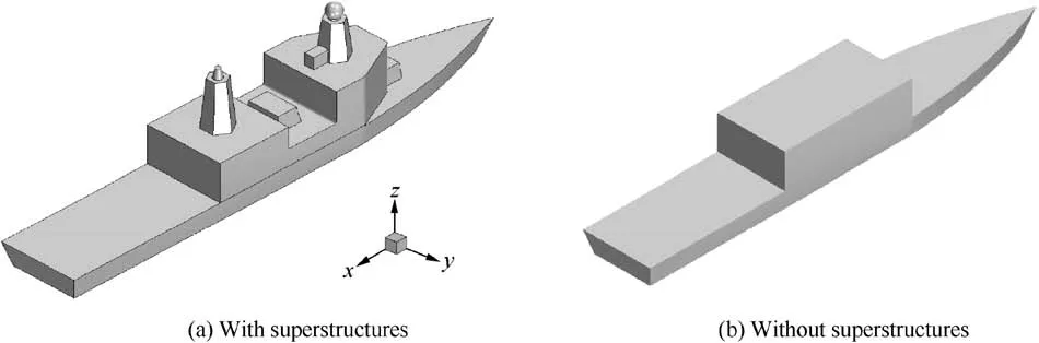
Fig.3 Sketch of LPD-17 ship model.

Fig.4 Schematic of aerodynamic modifications of ship model.
There are two ways to control the disturbed ship airwake.15First,the adverse aerodynamic environment,such as the recirculation zone and the free shear layer,can be eliminated or shifted out of the helicopter's landing route.The other one involves methods to reduce the intensity of the shedding vortex in landing area by limiting or filtering the flow above the deck.Based on this,we design three aerodynamic modifications of superstructures:aft ramp,notch and longitudinal flaps,as illustrated in Fig.4.The aft ramp is installed on the top of the hangar,and the length is about 1/6 of the hangar height.The rectangular notch is built on the top of the hangar,and the height and length are about 1/8 and 1/2 of the height of the hangar.In Fig.4(c),a series of distributed flaps longitudinally mounted on the top of the hangar with the space of 1/3 of the hangar height.The length,width and height of the modification are 1,1/40 and 1/6 of the hangar height,respectively.
A rectangular computational domain(8LS×6LS×6LS,whereLSis the overall ship length)is employed,and the sea and ship surface are specified as no-slip walls.The front and right-side surfaces are set as velocity-inlet boundary condition,while other surfaces are set as pressure-outlet boundary condition.The baseline ship/rotor mesh contains 6 million cells,and the mesh is refined in the vicinity of the ship deck where the actuator disk is located.Take the case of the aft ramp modification,Fig.5 shows the schematic of mesh system.The mesh around the aft ramp modification is further refined to maintain the calculation accuracy,resulting in 6.8 million cells.For the notch modification and flap modification,the refined mesh sizes are 7 and 7.5 million cells,respectively.The first wall unit value is set as 2 mm in order to meet the requirement of standard wall function in turbulence model.
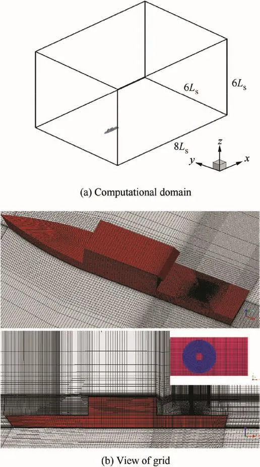
Fig.5 Mesh system used for ship/rotor simulation.
The incoming velocityV∞in the present study is 15 m/s and set to a uniform inlet profile.For the coupling rotor/ship simulations,5000 iterations are needed for the steady solvers for the convergence to ensure the robustness of the calculations.For the unsteady simulation,based on the incoming velocity and the minimum grid size,the time step for unsteady calculations is 0.002 s,and the internal iteration is 10 per time step.
3.Results and discussion
3.1.Headwind condition
The coupling flow is high disordered and unsteady,both the spatial and temporal disturbances of flow have influence on the rotor operations.In the present study,the control mechanisms that how the modifications affect the coupling flow and rotor airload is investigated from two aspects:space and time.
3.1.1.Spatial characteristics
Figs.6 and 7 show the overall and sectional iso-vorticity contour maps for four numerical cases.The velocity magnitudes are also included in Fig.6.When the air flows over the hangar,it separates at the corner of hangar because of its bluff body configuration.Then the separated air flow continues to move downstream and reattaches at the deck and thus forms a large recirculation region behind the hangar.In addition,two contra-rotating vortices are generated at both sides of the ship deck.As shown in two figures,the flow structure of ship wake is changed remarkably under the influence of flow control devices.In the case of the ramp modification,the flow separation can be delayed when the air flows along its surface.As compared with the baseline,the reduction in the strength of shedding vortices and the size of recirculation region generated behind the hangar are observed.Furthermore,the center of recirculation region is closer to the hangar door.For notch modification,two flow separations are captured in Fig.7.The first separation occurs at the notch corner and leads to a downward velocity component in flow field.When the disturbed air flows over the corner of the hangar door where the second separation occurs,it causes the decrease in vortex strength obviously.For flap modification,the large-scale vortex generated above the deck is divided into several smallscale vortices when the air flows over the distributed flaps.The numerical results show that the strength of vortex generated above the deck weakens,but the recirculation size is relatively unaffected.Moreover,the high vorticity can be seen in the top left of the diagrams in Fig.7,which is caused by the flow separation from the top front corner of the ship superstructure.
When the helicopter is landing to the deck,it hovers to follow up the ship above the hangar.In order to explore the effect of flow control methods on the velocity distribution above the flight deck,three lateral monitor lines alongy-axis,i.e.,x/L=0.25,0.50,0.75 are given and these lines are located in the plane 9 m above the deck,as shown in the Fig.8,the variation of downwash(downwardz-component of velocity)has more influences on helicopter operation than other velocity components.Fig.9 gives the velocity profiles ofz-velocity(Vz)at three monitor lines,and the velocity component is normalized byV∞.The ramp increases the downwash over the rotor plane,and the magnitude is higher at the fore part of the rotor than that at rear part due to the forward movement of large-scale recirculation.The increased asymmetry in longitudinal direction will play an important role in the longitudinal operation.In the case of the notch modification,the downwash at three monitor lines also increases,but the increment is small.As for the last modification,the flow is blocked and cut by the distributed flaps;thereby the magnitude of downwash is reduced.Although the vortex intensity is weaken,the flow is more disordered than other cases because several small-scale vortices are also introduced by the flow cut.
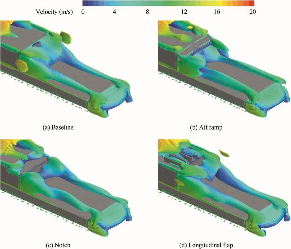
Fig.6 Iso-vorticity of coupling ship/rotor for four cases,colored with streamwise velocity.

Fig.7 Iso-vorticity contour map at longitudinal symmetry plane.
The comparison ofx-velocity(Vx)at three monitor lines is shown in Fig.10,and thex-velocity is normalized byV∞.The notch and ramp modifications increase thex-velocity as com-pared with baseline,which helps to increase the rotor loadings.While in the case of flap,both thex-velocity andz-velocity are decreased.
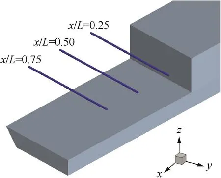
Fig.8 Schematic of monitor lines.

Fig.9 Comparison of Vzat three monitored lines.
Then,we discuss the effects of flow control on rotor airload during shipboard landing.The standard port-side deck landing maneuver is adopted,which includes the following steps(Fig.11):approaching the ship,hovering alongside the port,keeping station over the landing spot,and finally landing during the quiescent period.The most demanding step for the pilot is from the hovering alongside to station-keeping,because the helicopter's operations are most affected by the disturbed ship airwake.To study the effect of the controllers on the helicopter landing,the rotor aerodynamic forces at five discrete positions in the flying route are monitored,which is illustrated in Fig.12,and the plane that the rotor operates is 9 m above the flight deck(the hangar is 8 m in height).
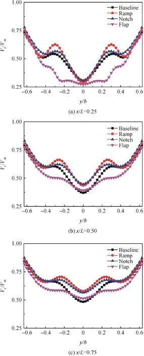
Fig.10 Comparison of Vxat three monitored lines.

Fig.11 Steps of standard port-side deck landing.

Fig.12 Schematic of monitored positions in flying route.
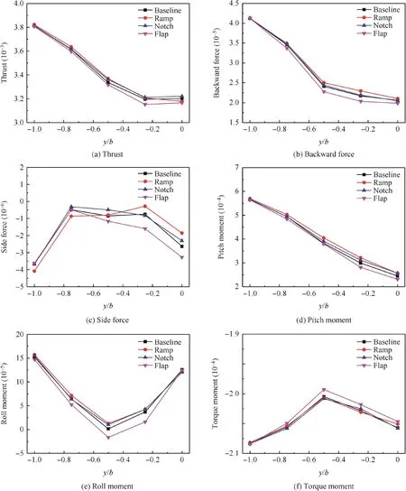
Fig.13 Variations of rotor forces and moments during lateral flight.
Fig.13 shows the variations of forces and moments during the lateral flight in head-wind condition where the rotor operates at the condition of rotor tip Mach number,Matip=0.643 and collective pitch, θ =12.82°.The force and moment are normalized by air density,rotor rotation speed and radius.It should be pointed out that,to get an insight into the variations of rotor airloads influenced by ship airwake,the rotor control inputs,i.e.collective and cyclic pitches,are kept constant in simulation.In baseline case,the rotor forces and moments gradually decrease during the helicopter translates from portside position to hover position over the deck.When the rotor is located above the deck edge(y/b=-0.5),the advancing blade is just immersed in the ship airwake and the asymmetry of relative in flow velocity on the rotor plane reaches the minimum.Therefore,the side force,roll and torque decrease first and then increase in the process of lateral flight.In headwind condition,both thex-andz-components of velocity account for the variation of rotor airloads.For ramp and notch modifications,although the downwardz-velocity increase,the largerx-velocity in ship airwake brings about the increase in the rotor thrust,while an opposite trend occurs in the case of flap modification due to the significant reduction ofx-component velocity.The rotor thrust,lateral and longitudinal moments directly relate to the collective pitch and the cyclic pitches,respectively,indicating that the additional operation input is needed for the flap modification.As a result,the reduction in the available operation margin has an adverse effect on the landing safety.In addition,the rotor backward force,side force and torque moment in flap case are larger than that of other cases;this results that the pilot should pay more attention to keep balance between the helicopter attitude and ship deck.
As stated above,the flow control methods indeed change the spatial variation of velocity and vortex field above the deck and impact the rotor forces and moments during the helicopter shipboard landing,but the improvement is limited as compared with the baseline case.
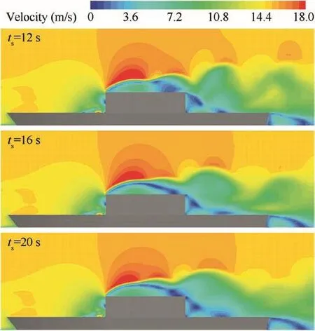
Fig.14 Contour maps of velocity at center slice for different time observations.
3.1.2.Temporal characteristics
The disturbed ship wake is also highly unsteady.Fig.14 shows the contour maps of velocity distribution at central slice at three time(ts)observations with a 15 m/s wind in the headwind condition.As can be seen,the ship airwake is time-varying,which leads to the unsteady loading on rotor and eventually decreases the handing quality.In this section,we study the time-varying property of ship wake and its influence on rotor unsteady loadings under different flow control means.
A variable,Turbulence Intensity(TI),is introduced to analyze the time-varying characteristics of the ship airwake.It is defined by the following expression:

Fig.15 Comparison of turbulence intensity of ship airwake.

Fig.16 PSD plot of time-varying thrust.

where σ andUlocalare the velocity standard deviation and the local mean velocity during the sample time,respectively.Considering the size of ship model and the in flow velocity,the sample time is set as 20 s.
Comparisons of TI computed by the total mean velocity among four cases are shown in Fig.15.The three monitor lines of velocity magnitude are located alongy-axis,i.e.,x/L=0.25,0.50,0.75,as shown in Fig.8.Because the aft ramp can delay and relieve the flow separation,the turbulence intensity is lower than the baseline.By contrast,the flap modification increase the turbulence intensity due to the formation of more vortex.
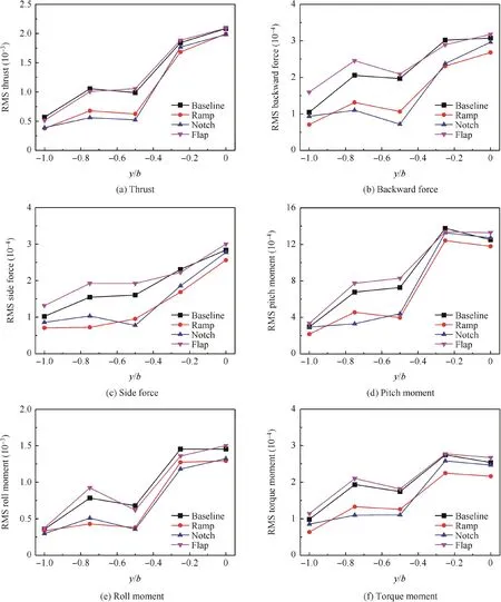
Fig.17 Variation of RMS loadings in headwind condition.

Fig.18 Schematic of aerodynamic modifications of ship model in crosswind condition.
Fig.16 shows the PSD plot in terms of the thrust time history,including the history of rotor thrust in baseline case,in which the rotor is 9 m above the center of the flight deck,namely the locationy/b=0 in Fig.12.Affected by the unsteady ship wake,they fluctuate significantly with time and the perturbation magnitudes are about 10%-20%of the steady values,and the dominant frequencies of rotor thrust is<3 Hz.The high-frequency disturbances of ship airwake do not increase the pilot's difficulty in operation due to the helicopter's inertia,while the low frequency disturbances,especially in the range of 0.1-3 Hz that with great energy,might bring about the amplitude displacement of helicopter,and the pilot needs to correct controls continuously to keep balance.Therefore,to effectively evaluate the magnitude of the unsteady disturbance,the RMS loading(e.g.RMS thrust)within the frequency bandwidth of 0.1-3 Hz is introduced.The RMS is defined as2
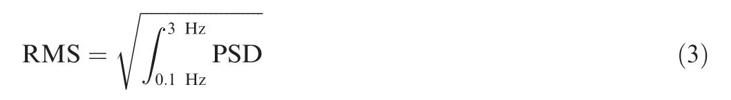
Fig.17 shows the comparison of RMS loadings of six component aerodynamic force for four cases.The locationsy/b=0 andy/b=-0.5 represent the center and left-side of deck,respectively.When the helicopter hovers above the landing spot,i.e.,y/b=0,the rotor is completely immersed in the unsteady ship airwake and the unsteady perturbations of the forces are greater than those of other positions.Between-1<y/b< -0.25,there are very encouraging reductions in RMS loadings for the ramp and notch modifications,except the slight increase in RMS pitch above the landing spot.It means that the two modifications are beneficial to relieve pilot's workload,but the flap modification exhibit negative effects in most conditions.As stated in Section 3.1.1,the flap reduces the strength of the vortices,meanwhile brings about some adverse effects,such as multiple separations and small scale vortex.However,it does not mean that the flow quality cannot be improved by filtering and cutting.If the smaller flap,such as net device,is used to filter the large scale vortex in the ship wake,beneficial results may be achieved.Limited by the capacity of the present numerical method,the experimental study will be carried out in our future study.
3.2.Crosswind condition
In this section,we further investigate the effectiveness of flow control modifications on ship wake and rotor aerodynamics in crosswind conditions.In the case of crosswind,the shedding vortex and the shear layer separate from the side edges of the hangar,thus the original ship model with complex superstructure in Fig.3(a)is used.Two modifications,i.e.ramp and notch,are installed at the right-side surface of the hangar,as shown in Fig.18.
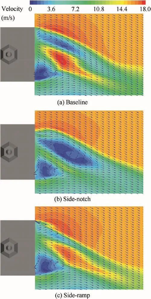
Fig.19 Velocity contours in horizontal plane for three cases at starboard 30°WOD.
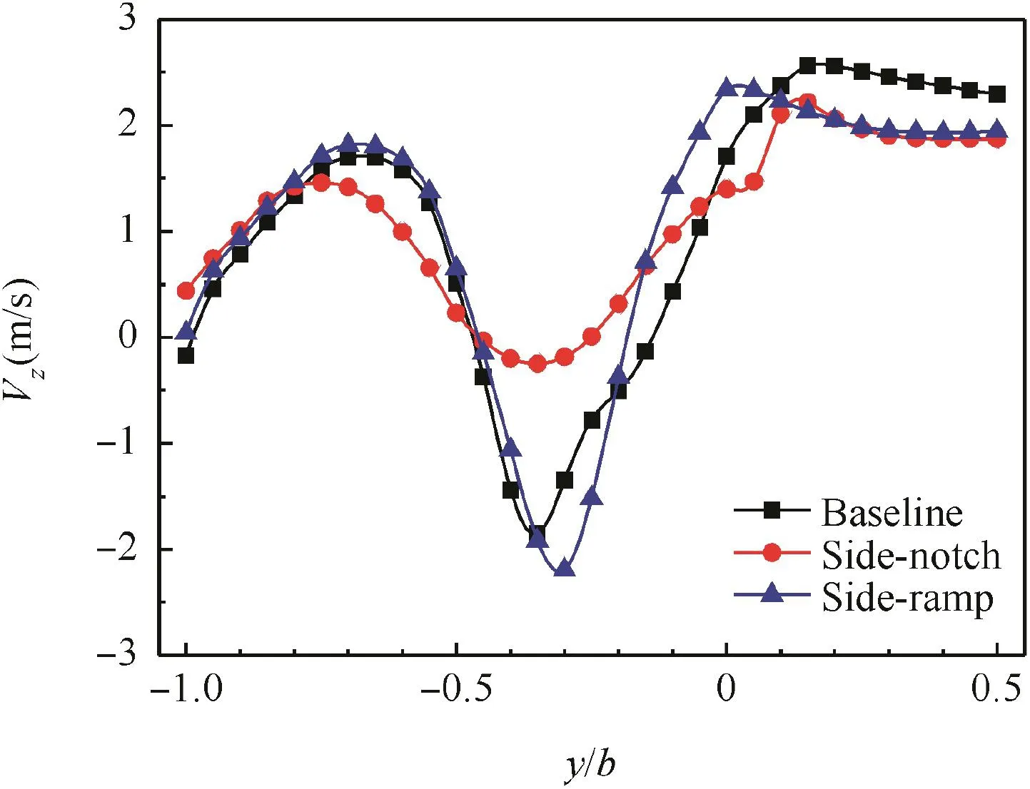
Fig.20 Comparison of vertical velocity between baseline,sidenotch and side-ramp.
Fig.19 shows the contours of total velocity in the horizontal plane(8 m above the deck)at starboard 30°WOD,and the incoming wind speed is the same as that in the headwind condition.The distribution of velocity vector is also shown in the figure.Due to the blocking effect of the ship tower and the hangar,two low-velocity regions with vortex are generated at both sides of the flight deck.Compared to the baseline,the side-notch modification makes the low-velocity region at the right side of the deck shift to the deck center,leading to the improvement of velocity distribution,despite the unsteady level of velocity vector increases little at the center of flight deck.For the side-ramp modification,it is noted that the deflection angle of velocity vector is smaller than that in the baseline,as the WOD is consistent with the installation angle of the modification,which is advantageous to the delay of flow separation.
Fig.20 presents the comparison of vertical velocity along a monitoring line(8 m above the deck,16 m away from the hangar)at 30°WOD.The increased downwash reduces the effective angle of attack of the main rotor blades and hence the rotor thrust,which further reduces the available control margin of helicopter operations.The peak of downwash is clearly seen at the left side of deck(-0.5≤y/b≤0),and the explanation for this is that the shedding vortex separating from the top of ship tower contains the large vertical velocity component.As seen in the figure,there is an obvious improvement in the vertical velocity distribution of the side-notch modification,while the side-ramp modification has little effects.
Fig.21 shows the variations of RMS forces and moments for the baseline,notch and side-ramp modifications during lateral flight at starboard 30°WOD.The monitor locations of rotor RMS loadings are shown in Fig.12.Different from the headwind condition,the peak of RMS loadings occurs aty/b=-0.5(left-side deck edge),where the rotor is wholly immersed in the ship wake in this condition.As shown,the notch modification is equally as effective as the side-ramp modification over the landing spot(y/b=0)with reduction of 10%-25%in all RMS loadings and an improvement of 15%-35% between-1≤y/b≤ -0.25,in RMS roll is achieved.For RMS thrust aty/b=-0.25,by 49%the notch modification has reduced the peak levels.The reduction of RMS loadings for the side-ramp modification can also be seen between-1≤y/b≤ -0.25,where there are very encouraging reductions in RMS thrust of up to 50%.
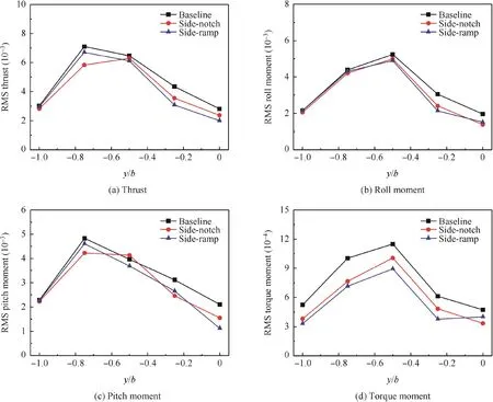
Fig.21 RMS loadings for three cases in starboard 30°WOD.

Fig.22 RMS loadings for three cases in starboard 15°WOD.
Then,the numerical cases in starboard 15°WOD are conducted.Fig.22 maps the RMS thrust,pitch,roll and torque moments in this condition.From the port to the deck center,the RMS airload gradually increases,because the region with the maximum turbulence intensity still locates around the deck center in the small WOD.As illustrated in the figure,the RMS forces and moments can be reduced through two modifications,especially in the case of the ramp.It is also interesting to note that the modifications can change the ship wake and improve the RMS airload better in this condition by comparing it with starboard 30°WOD in Fig.21.In addition,there are fluctuations in the distribution of RMS loadings for the side-notch modification,which might be explained by the fact that multiple flow separations caused by the step structure of notch modification would increase the lateral gradient of unsteady characteristics in the coupling flow field.
4.Conclusions
A numerical study on flow control of ship airwake during the shipboard landing is presented in this paper.Steady and unsteady simulations are carried out separately to investigate the effect of spatial and temporal variations of ship airwake on the rotor airload under different flow control methods.From the results stated above,the following conclusions can be drawn:
(1)All the flow control methods obviously change the spatial variation of ship airwake.The ramp and notch modifications reduce the strength of shedding vortex behind the hangar through delaying and relieving flow separation,respectively.The results regarding rotor airloading also illustrate that the flow control methods are beneficial to increase the overall rotor airload and alleviate the reduction of the available operation margin,but the improvement arising from spatial change of ship airwake is limited.
(2)The time-varying ship airwake can cause the serious oscillation of rotor forces and moments during shipboard landing.The simulations show that the turbulence intensity of unsteady ship airwake and oscillatory rotor airloading in terms of RMS loading can be remarkably reduced by the ramp and notch modifications.It means that these flow control methods have large potential benefits to improve the handing quality.
(3)From the results of flap modification,it can be concluded that the control device should not only reduce vortex strength of ship airwake,but also improve the flow quality and void the production of small-scale vortex.For example,if the smaller flap,such as net device,is used to filter the large scale vortex in the ship wake,improved result may be achieved.
(4)The fixed modifications are investigated in the present paper for mechanism study.The simulation results illustrate that the control devices improve the ship airwake and rotor airload better in small WOD conditions and limit in the large WOD as the flow structure changes with WOD condition.In our future work,the parametric study will be carried out to design the adaptive control devices,which can work well in most conditions.
Acknowledgement
This work was supported by the Fundamental Research Funds for the Central Universities(No.NS2018007).
杂志排行

CHINESE JOURNAL OF AERONAUTICS的其它文章
- A review of chatter vibration research in milling
- Impact of reduced frequency on the time lag in pressure distribution over a supercritical airfoil in a pitch-pause-return motion
- Thermal state calculation of chamber in small thrust liquid rocket engine for steady state pulsed mode
- Sliding mode control design for oblique wing aircraft in wing skewing process
- Adaptive optimization methodology based on Kriging modeling and a trust region method
- Aircraft engine fault detection based on grouped convolutional denoising autoencoders