Active disturbance rejection based load frequency control and voltage regulation in power systems
2018-11-02LiliDONGAnusreeMANDALIAllenMORINECYangZHAO
Lili DONG,Anusree MANDALI,Allen MORINEC,Yang ZHAO
1.Department of Electrical Engineering and Computer Science,Cleveland State University,Cleveland,OH 44115,U.S.A.;
2.Department of Transmission Substation Services at FirstEnergy Corp,76 South Main Street,A-Go-11,Akron,OH 44308,U.S.A.Received 1 June 2018;revised 21 September 2018;accepted 28 September 2018
Abstract
An active disturbance rejection controller(ADRC)is developed for load frequency control(LFC)and voltage regulation respectively in a power system.For LFC,the ADRC is constructed on a three-area interconnected power system.The control goal is to maintain the frequency at nominal value(60Hz in North America)and keep tie-line power flow at scheduled value.For voltage regulation,the ADRC is applied to a static var compensator(SVC)as a supplementary controller.It is utilized to maintain the voltages at nearby buses within the ANSI C84.1 limits(or±5%tolerance).Particularly,an alternative ADRC with smaller controller gains than classic ADRC is originally designed on the SVC system.From power generation and transmission to its distribution,both voltage and frequency regulating systems are subject to large and small disturbances caused by sudden load changes,transmission faults,and equipment loss/malfunction etc.The simulation results and theoretical analyses demonstrate the effectiveness of the ADRCs in compensating the disturbances and achieving the control goals.
Keywords:Active disturbance rejection control,power systems,load frequency control,static var compensator,voltage regulation,disturbance,system uncertainty
1 Introduction
A power system consists of generation,transmission,distribution,and load.The majority of power systems use three-phase AC power which meets the strong needs for economic transmission to great distances.In an AC power system,the power absorbed or delivered by the resistive components of a RLC load is called active(or real)power with a unit of watt(W),while the power absorbed or delivered by the reactive parts of the load(such as capacitors and inductors)is named as reactive power whose unit is defined as volt amperes reactive,or var[1].The active and reactive powers in a transmission network are independent of each other,and controlled separately[2].The changes of active power influence system frequency.As gener-ation chases load variations,frequency deviates from scheduled values.Therefore,active power is related to load frequency control(LFC).The variations of reactive power affect bus voltage.Therefore reactive power is associated with voltage control[2].As stated in[1],“sustained operation of power systems is impossible unless generator frequencies and bus voltages are kept within strict limits”.In addition,“a reliable power system must remain intact and be capable of withstanding a wide variety of disturbances”such as sudden load changes,transmission system faults,equipment loss/malfunction and so on[1].LFC and voltage control are utilized to keep the constancy of frequency and voltage despite the presence of disturbances,so as to ensure the sustained operations and stability of power systems.The dynamic performance of a power system is dependent on the effectiveness and robustness of LFC and voltage control[3],both of which maintain a balance between load and generation.Once the balance is broken,power system blackouts are likely to occur[1].The famous North American blackout of 2003 was linked to the short-term(10–50h)system instability triggered by disturbances[4].Therefore a robust control system against disturbances is essential for a reliable power system.
Modern power systems consist of multiple control areas which are connected with each other via tie lines.In each control area,any sudden load perturbation could cause the normal operating point of a power system to vary from its prescribed values.As a result,the deviation occurs about the operating point such as nominal system frequency and scheduled power exchange to the other areas[5].The LFC is thus used to stabilize the system frequency at around 60Hz(the standard frequency in North America),and keep tie-line power flows at scheduled values[6].The linear combination of frequency deviation(Δf)and net power interchange error(ΔPtie)is defined as area control error(ACE).The major objective of LFC is regulating the ACE.As the ACE is driven to zero by LFC,both Δfand ΔPtiewill bedriven to zero as well[2].In the literature,the LFC has been investigated for almost five decades[6–8].The PI/PID based LFC is the most established solution in power industry[5,9–16].Although the PI/PID controllers are easy to implement,they are not effective to provide satisfactory dynamic performance in the presence of various load changes[17].Long settling time and large overshoot are the primary hindrances of PI/PID controllers.Nowadays the power systems are undergoing unprecedented changes with the incorporation of large number of renewable energy sources,distributed generation and demand response.These changes introduce significant uncertainties and disturbances to the power system control.Traditional PI/PID controllers are not robust against such uncertain systems with large disturbances.Consequently many advanced control methods have been proposed for LFC[6–8].Such advanced controllers include optimal control approaches(particle swarm optimization algorithms,tabu search algorithms and bacterial foraging optimization algorithm etc.),adaptive and selftuning methods,robust approaches such as H∞control,LQG,and μ analysis,and intelligent approaches consisting of artificial networks,fuzzy logic,genetic algorithms and so on[6–8].Among these advanced controllers,an emerging robust control technology entitled active disturbance rejection control(ADRC)is initially applied to three-area power systems by Dong et al.[18,19],and is demonstrated to be an effective LFC.In[18,19],non-reheat,reheat,and hydraulic turbines are located in the three different areas respectively.The ACE,Δf,and ΔPtieare successfully driven to zero despite the presence of various types of disturbances(i.e.,large step load change,random load change,and loss of equipment)[19].The ADRC mainly relies on the reference input,output,and the order of a system.In its framework,the difference between the mathematical and actual system models is defined as a generalized disturbance(GD).The GD is estimated by an extended state observer(ESO)and then compensated by a feedback controller in real time.Because the ADRC is independent of an accurate mathematical model,it is very robust against system uncertainties and external disturbances.Therefore the ADRC is a natural fit for modern complex power systems.Following[18,19],more ADRC-based LFCs are presented in literature[20–25].The nonlinear part associated with a turbine named as generation rate constraint(GRC)is investigated in[20],where an anti-GRC scheme is added to the ADRC.In[21,22],two different algorithms that are used to optimize the controller parameters of ADRC are discussed.They are diminishing step fruit fly optimization algorithm(DSFOA)[21]and gravitational search algorithm(GSA)[22].A reduced-order ADRC is applied to the power system in[23],where one non-dominant pole is disregarded for the transfer function model of each area.The same ADRC as in[18,19]are employed to regulate frequency deviations for two-area and four-area power systems respectively in[24,25].It is verified in[18–25]that the ADRC is not only robust against disturbances and model uncertainties,but can compensate nonlinearities for multiple-area power systems.In addition,compared to the other advanced controllers[6–8]with numerous tuning parameters,the ADRC with linear ESO only has two(one for controller and the other for ESO).This advantage makes it simple to implement in practice.
Besides frequency control,voltage control is vital to the satisfactory performance of a power system.It is more efficient to transmit power at high voltages for a long distance than at low voltages[2].The generator voltages are usually in the range of 11 to 35kV.The voltages(from generators)are stepped up to the transmission voltage level(typically 230kV and above),and then stepped down to the sub-transmission level[2].The distribution systems represent the final stage in power transfer to the end users(industrial,commercial,and residential customers),who are supplied with the utilization voltage such as 120V(single phase)in North America.The objective of voltage control is maintaining the voltages at different buses within ANSI(American National Standards Institute)C84.1 limits(or±5%tolerance).The control of voltage levels is accomplished by adjusting the production,absorption,and flow of reactive power at all buses in the power system.The generating units provide the basic means of voltage control through automatic voltage regulators[1,2].Nevertheless,additional means are required to control voltages throughout the transmission and distribution systems[2].Among the devices that could serve this purpose,the static var compensator(SVC)is the dominate one that has been extensively used in power industry for decades due to its low cost and efficiency.The SVC is a device in the family of the flexible alternating current transmission system(FACTS)[26].It senses the voltage from the transmission grid and maintains the voltage at a nominal level by supplying or absorbing reactive power to and from the grid.However,the irregular disturbances in a power system make it very difficult for the SVC to achieve ideal voltage regulations.The robustness of the SVC is inadequate to withstand large,sudden,or rapidly changing load disturbances.The ability of SVCs is limited by delays in reactive power measurement[27].Consequently,the var output of a SVC sometimes drops during voltage sag,and increases during voltage swell[28],causing the instability of power systems.In addition,a poorly tuned SVC could give rise to voltage oscillations in the power system with varying disturbances[28].Therefore,a supplementary controller shall work together with the SVC to enhance its robustness and stability.Different control techniques have been developed for SVC systems.In addition to conventional PID controllers[29–31],the advanced control methods have been applied to SVCs such as adaptive backstepping sliding mode H∞control[32],adaptive fuzzy logic control[33],dual-function neuron-based external controller[34],adaptive sliding mode control[35],and others[36].The PID controllers[29–31]have aforementioned problems(as we discussed in load frequency control).The advanced controllers in[32–36]are complex in structure and difficult to implement.An ADRC is merely a combination of ESO and a feedback controller.The simple structure and robustness make it convenient and easy to use in the SVC.An ADRC with nonlinear ESO is applied to the SVC in[37,38].The ADRCs with both linear and nonlinear ESOs are constructed on the SVC in a wind power system with asynchronous generators in[39].The nonlinear ESO is as effective as a linear ESO in estimating GD.However,the former has multiple tuning parameters while the latter only has one.In this paper,an ADRC with linear ESO is developed for the power system in North America where synchronous generators are typically used[1].Both step disturbances and random time-varying disturbances are added to the SVC system to test the robustness of the ADRC.Besides the classic ADRC,an alternative ADRC is originally developed for the SVC.For the design of alternative ADRC,the known part of the SVC model is utilized in control law.The ESO is only used to estimate the unknown part of the system and external disturbances.With available model information,the alternative ADRC shows better transient performance than classic one in later simulation studies.The former also requires smaller controller gains than the latter.The focus of this paper is on the development of an ADRC for the two major control loops of power systems:LFC and voltage control separately in the presence of various disturbances.
The rest of this paper is organized as follows.The ADRC for annth-order system withmnumber of inputs is developed in Section 2.The application of ADRC to LFC is discussed in Section 3.The alternative ADRC for voltage control is developed in Section 4.Concluding remarks and future research are given in Section 5.
2 Classic ADRC design
The ADRC is originally designed by Han in a nonlinear form[40,41],and later linearized by Gao[42–44]for the easiness of implementation and vast applicability.The linear ADRC(with linear ESO)achieved enormous success in motion control[45],Micro-Electro-Mechanical Systems[46,47],web tension[48],automobile systems[49,50],power systems[18–25],and many other areas.In this section,the classic linear ADRC is derived for annth order system withmnumber of inputs and external disturbances[18–20].The general form of annth order system is given by

whereY(s),U(s)andD(s)are the Laplace transforms of output,input,and external disturbance of the system,andG(s)is the plant transfer function(TF):

In(2),ai(i=0,...,n)andbi(i=0,...,m)are the constant coefficients forG(s).The differential equation model for(1)is given by

whereu(t),y(t)andd(t)are the input,output and disturbance for the system.Integratingmtimes both sides of(3)yields

whereb=bm/an,r=n−m,andf(y(t),u(t),d(t))(orf)is the GD which includes all the terms except forbu(t)andy(r)(t).We choose state variables asx1=y,x2=,...,xr=y(r−1),andxr+1=f.Supposefis differentiable within the interests,andh= ˙f.Then the state-space model of(4)is represented by

whereX=[x1,x2,...,xr+1]T,

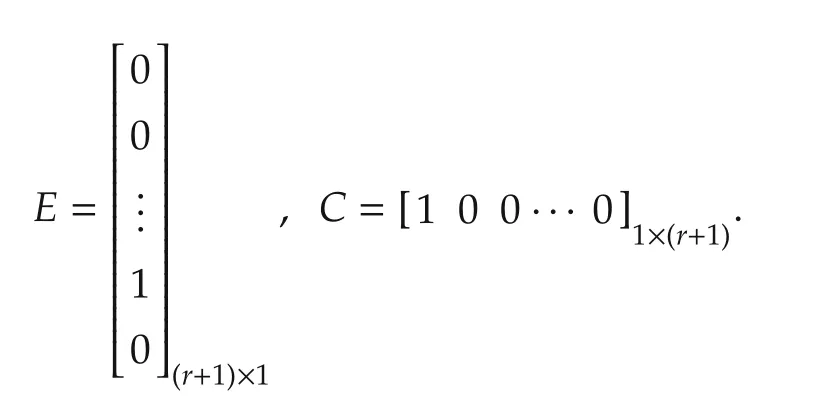
For a classic ADRC,an ESO is used to estimate both system states and the GD(orf).The ESO is represented by

where the observer state vectorZ=[z1,z2,...,zr,zr+1]Twithz1≈y,z2≈,...,zr≈y(r−1),andzr+1≈f,and observer gain vectorL=[β1,β2,...,βr,βr+1]T.The observer gains β1,...,βr+1are selected in such a way that the characteristic equation of the ESO will be(s+ωo)r+1where ωois a positive observer bandwidth.From[44],we have

The observer statezr+1is used to approximatef,the GD.We choose the control law as

whereu0is to be determined.Supposezr+1is an accurate estimate off.Substituting(8)into(4)yields

Our control goal is drivingyto a constant reference signalr.Then the simplified system(9)can be controlled by a state feedback controller(u0)with controller gainsk1,k2,...,kr:

Let the statesy,,...,y(r−1)in(10)be replaced by their estimatesz1,z2,...,zr.Substituting(10)into(8),we obtain the control law as

whereK=[k1,k2,...,kr,1]is controller gain vector.The controller gains are chosen in such a way that the characteristic equation of the feedback controller is(s+ωc)r,where ωcis a positive controller bandwidth.According to[44],we have

From the equation development above,we can see that there are only two tuning parameters for the ADRC.They are controller and observer bandwidth ωcand ωorespectively.Therefore,the ADRC is simple to implement,and easy to tune.In addition,the unknown system dynamics and external disturbances are included in the GD,and actively compensated by the feedback controller.Therefore,the ADRC is robust against system uncertainties and disturbances.
3 Application of ADRC to LFC
In an interconnected power system,LFC is used to stabilize frequency oscillations despite the presence of load disturbances.In the modern world,the power industry is in a transition from vertically integrated monopolistic power utility to a structure under deregulation where competitive markets exist[7].The transition not only increases the complexity of power system,but introduces uncertainties to system modeling.Furthermore,various types of apparatuses with large capacity and fast power consumption increase power load changes(or disturbances)significantly[8].These substantial disturbances and model uncertainties make it difficult to achieve ideal frequency control.Therefore,a LFC that is reliable(i.e.,performing intended functions in normal conditions),robust(i.e.,working under perturbations and system variations),and economic is highly in demand.As presented in Section2,ADRC is robust against both system uncertainties and external disturbances.It is cost-effective due to its simple structure and easiness of tuning.Therefore,the ADRC meets the demands of LFC,and is an ideal solution to frequency stabilization problem.In this section,the ADRC is developed and tested on a three-area interconnected power system.
3.1 Dynamic model of three-area power system
The power system is illustrated in Fig.1,where three areas are connected with each other through tie lines.Each area hasngenerating units that are owned by different generation companies(or Gencoij,wherei=1,2,3;j=1,...,n).In Fig.1,ΔPL1,ΔPL2,and ΔPL3represent active power load changes.Every generating unit consists of a turbine,a generator,and a governor.The governor is a device to sense the frequency bias caused by the load change.The input and output of the governor are electrical power change ΔPeand valve position change.In order to ensure satisfactory and stable parallel operation of multiple units,the speed governor is provided with droop characteristic(denoted byR).Turbine is used to transform the natural energy,such as from steam(for non-reheat and reheat turbines),into mechanical power(ΔPm)that is supplied to the generator.

Fig.1 Schematic diagram of three-area power system.
Here we use non-reheat turbine as an example to construct the ADRC-based LFC.DefineGET(s)as the transfer function from ΔPe(s)to ΔPm(s).TheGET(s)for non-reheat turbine is

The generator converts the mechanical power from turbine to electrical power.A change in active power demand is reflected throughout the system by a change in frequency(Δf).As generation chases load variations,frequency and tie-line power flow deviate from their scheduled values.DefineMas area inertial constant,andDLarea load damping constant.The TF of the generator is

The goal of LFC(ADRC)is to regulate the frequency deviation(Δf)and tie-line power error(ΔPtie)in the presence of varying active power loads.Specifically it is utilized to control ACE to zero.The measurable ACE is defined as

whereBis area frequency bias setting[2].Fig.2 shows the block diagram of a generating unit with a non-reheat turbine.

Fig.2 The block diagram of a generating unit with non-reheat turbine.
From Fig.2,the ACE output(orY)is given by

where

Define

Then(16)can be rewritten asY(s)=GP(s)U(s)+D(s),which matches the general form(1).Therefore,each generating unit can be controlled by the ADRC developed in Section2.From(13)–(16),the relative system order for each generating unit is three.Therefore,a fourth-order ESO can be utilized to estimate the system states and GD for the generating unit.
3.2 Simulation results
The performance of the ADRC is compared to that of the PI controller which is tuned by genetic algorithm linear matrix inequalities(GALMI)[5].In order to conduct the comparison study,we build the ADRC and GALMI-based PI controllers on the same three-area power system model as in[5]where three Gencos are distributed in each area with non-reheat turbines.The two control systems are simulated in Matlab/Simulink[19].The controller and observer bandwidths of the ADRC for three areas are ωc=4rad/s,and ωo=20rad/s.The PI controller gains are given in[5].The parameter values of the power system can be found in[2,51].In order to test the robustness of both controllers against large disturbances,a step load change with large magnitude is added to each area att=2 seconds.The magnitudes of the load changes are ΔPL1=100MW,ΔPL2=80MW,and ΔPL3=50MW,respectively.The ACEs,frequency errors,and control efforts(ΔPc)are illustrated in Figs.3–5.
These figures show that the ADRC produces smaller overshoot and shorter settling time than PI controller in ACE and frequency errors.However,the control efforts of the ADRC have small spikes at the beginning of simulation.The spike could be caused by the slight lag of ESO in response to external disturbance.Nevertheless,the peak value of the control effort of the ADRC is no more than 0.2p.u.,which is reasonable in practice[2,19].The ADRC shows superior transient performance to PI controller.

Fig.3 System responses and control efforts in area1(reprinted from[19]with permission from Elsevier).

Fig.4 System responses and control efforts in area2(reprinted from[19]with permission from Elsevier).
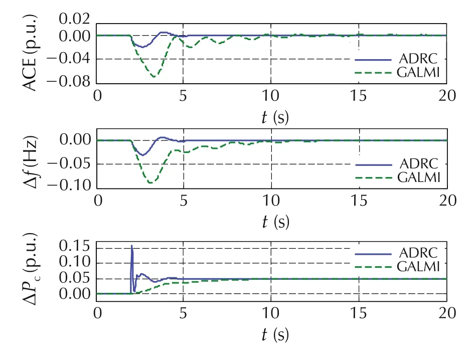
Fig.5 System responses and control efforts in area3(reprinted from[19]with permission from Elsevier).
4 Application of ADRC to SVC
SVCs are shunt-connected static generators and/or absorbers of reactive power[3].Their outputs are varied so as to control the voltage of the electric power system.The control goal is to maintain the voltages at nearby buses within ANSI C84.1 limits(or±5%tolerance).The problems of maintaining voltages within the required limits are complicated by the fact that the power system is subject to different kinds of disturbances that could cause voltage sags or swells.Both step and random disturbances are common in power systems.Here the ADRC is utilized to effectively compensate the disturbances,and keep constant voltages for the reliable operation of power systems.
4.1 Dynamic model of SVC
The single-line diagram of a SVC is shown in Fig.6.The SVC system mainly consists of a voltage measuring device,voltage regulator,thyristor susceptance controller,and transmission network.The voltage measuring device is used to measure the positive-sequence voltage from the network.The measured voltageVmis compared with the reference signalVref,which is the desired or nominal bus-line voltage(usually considered as 1p.u.).The voltage error betweenVrefandVmis regulated by a voltage regulator,which outputs susceptanceB.Distribution unit,synchronization unit,thyristor switched capacitor(TSC)and thyristor controlled reactor(TCR)constitute the thyristor susceptance control.Using the susceptanceB,the distribution unit computes the firing angle which determines switching on/off of the TSC and/or TCR[26].The synchronization unit keeps the firing of the thyristors in synchronism with the frequency of the AC voltage so that the firing angle α does not drift.The synchronous timing is provided by a phase locked loop(PLL)[26].Depending on whether the busline voltage is above or below the terminal voltage level,the SVC will either absorb or generate reactive power through controlling TSC and TCR.
The simplified diagram model of the SVC is shown in Fig.7 whereerepresents the difference betweenVrefand the measured voltage(from voltage measuring device,of whichH(s)is the TF),Vsis an external disturbance voltage,andGR(s)is the TF of voltage regulator.The thyristor susceptance control is modeled byGB(s).It generates pulses to turn on or off the TCR and TSC based on the firing angle of the thyristors to control vars.The output of susceptance controlBSVCis multiplied by the voltage(VT)from the transmission line to yield current(ISVC),which is then sent to the networkGN(s).
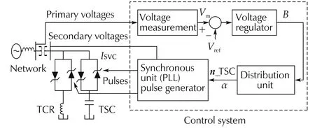
Fig.6 Single-line diagram of SVC[26].
The TF of the voltage measuring device is

whereTmis the time constant of voltage measuring device.The TF of the voltage regulator is given by

whereTis the time constant of regulator,andKSLis the reciprocal of the droop characteristic.According to[2,52],the TF model of the thyristor susceptance control is given by

whereTdis the gating transport delay,andTBisthetime constant of thyristor firing sequence control.From[2],the parameterTdhas such a small value that it is normally neglected,making e−Tds=1.Therefore,(23)is rewritten as

The network,GN(s),can be represented by a constant.Combining(21),(22),and(24),we have a third-order loop gain TF as follows for the SVC system:

whereis a constant.According to(2)–(6),a fourth order ESO is needed to estimate the states and GD for the third-order system given by(25).The classic ADRC based on(5)-(12)can be developed for the SVC.

Fig.7 Simplified transfer function model of SVC.
4.2 Alternative ADRC design
In the SVC system,the parameter(TB)of thyristor susceptance control could vary significantly with the rapid changes of inductive load while the other two parametersTandTmare almost unaltered[52].Therefore,we can divide the TF in(25)into two parts:the known and unknown.Suppose−A0,−A1,and−A2are negative open-loop poles.Then(25)is rewritten as

whereY1(s)is the measured voltage,andU1(s)is the input of SVC including both disturbance(d′)and control effort().For alternative ADRC design,an ESO is employed to estimate the unknown dynamics only.The available information of the plant is utilized in the controller design.The differential equation model of(26)is


Equation(27)can be rewritten as

The state variables for(29)are chosen as:=y1,andis bounded.The state equations are

where

The four system states can be estimated using the ESO:


The reference signal(r1)for nominal voltage should be 1p.u.The control law is then designed as

where the controller gains are given as follows:

From(12),the controller gains of classic ADRC for a third-order system are,3,and 3ωc.Since bothA1andA2are positive for the SVC system,(35)shows that the controller gains of alternative ADRC are smaller than the ones for classic ADRC.Smaller controller gains are easier to implement in practice.Therefore,this is one advantage of alternative ADRC over the classic one.
4.3 Stability and robustness analyses
The performance of a power system could be degraded by various types of disturbances.In addition,model uncertainty broadly exists in the SVC system.In this section,we study the robustness of the ADRC against disturbances and system uncertainties.The block diagram of a closed-loop SVC control system is shown in Fig.8,whereH(s)is a prefilter,C(s)represents the controller(classic or alternative ADRC).The details of TF development for constructing Fig.8 can be found in[19,44,46].The nominal values of system parameters for SVC are provided in[2,52].In the following frequency-domain analyses,the parameters ofKSL,TB,andTmare changed between−15%and+20%of their nominal values.

Fig.8 Closed-loop control system.
The Bode diagrams of the loop gain transfer function(from Fig.8)are illustrated in Figs.9 and 10.For classic ADRC,the gain margins are ranging from 13.2dB to 19.1dB,andthe phasemargins are rangingfrom 92.5°to 94.6°.For alternative ADRC,the gain margins are ranging from 14dB to 15.7dB,and the phase margins are ranging from 98.4°to 100°.The positive stability margins indicate the stabilities of the closed-loop system with both ADRCs despite the presence of parameter variations.
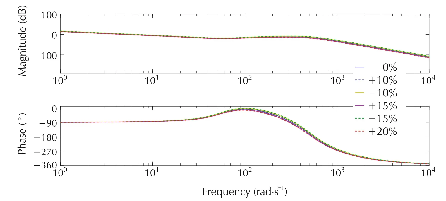
Fig.9 Bode diagrams of loop gain transfer function with varying parameters for classic ADRC controlled SVC system.
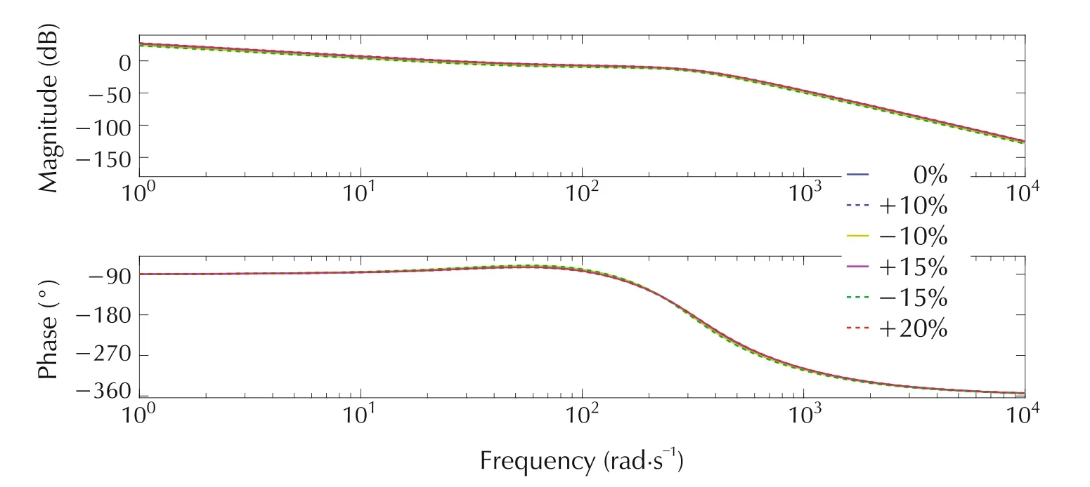
Fig.10 Bode diagrams of loop gain transfer function with varying parameters for alternative ADRC controlled SVC system.
The Bode diagrams of the TF between input disturbanceD′(s)and outputY1(s)are shown in Figs.11 and 12.The figures demonstrate excellent disturbance rejection properties of both classic and alternative ADRC that are unaffected by the variations of the system parameters.The Bode diagrams in this section not only demonstrate the stability of two ADRC controlled SVC systems,but also show the robustness of both controllers against disturbances and system uncertainties.

Fig.11 Bode diagrams of disturbance transfer function for classic ADRC in the presence of parameter variations.

Fig.12 Bode diagrams of disturbance transfer function for alternative ADRC in the presence of parameter variations.
4.4 Simulation results
In this section,we simulate ADRC controlled SVC system in Simscape Power Systems(of Matlab/Simulink).Unlike the Simulink model that is based on the mathematical model of a physical plant,Simscape Power Systems contain real models of electrical power components,including three-phase machines,electric drivers,and components for such applications as FACTS.It helps us develop and test system-level performance,and provides a way to construct realistic power system model.The Simscape Power System model for a SVC control system is shown in Fig.13.The model consists of a network with a 500kV voltage source,three-phase series RLC branch which represents the system impedance and load.The network is rated at 3000MVA with an X/R ratio(or system reactance/resistance ratio)of 10 and the load is 10MW.The SVC model is connected to the three-phase network.The internal structure of the voltage regulator in the SVC block is illustrated in Fig.14,where the output of voltage measuring device(V1meas),and the reference signal(Vref)constitute the input of ADRC.We use per unit system in simulation results.For a per unit system,if the actual voltage is controlled to be same as the base/nominal voltage,the per-unit voltage will be 1.0p.u.
As shown in Fig.14,different kinds of disturbances are added to the transmission network respectively.Here we apply both large and small disturbances to the SVC system.Large voltage disturbances are usually represented by step disturbances,which include positive and negative step disturbances.A positive step disturbance stands for loss of load,while a negative step disturbance represents loss of transmission line,transformer,or generator.Small voltage disturbances are caused by sudden incremental change in the load[2].Operating a steel mill’s arc furnace,starting a large induction motor,and energizing a transformer are the examples of small voltage disturbances.A small disturbance can be represented by the random disturbance with randomly varying magnitude and frequency.Small voltage disturbances create power quality problems such as voltage flicker;whereas large voltage disturbance can cause voltage collapse which results in stability issues and blackouts.The robustness of the ADRCs against these disturbances is tested in simulation.

Fig.13 SVC control system in Simscape power systems.

Fig.14 Internal structure of the voltage regulator in Simscape power systems.
Our control goal is to maintain the steady state voltage within 5%of nominal voltage(i.e.,0.95–1.05p.u.)at nearby substation buses and at the end-user customers,who utilize 120V RMS in North America.Classic and alternative ADRCs are applied to the SVC separately.The controller and observer bandwidth(ωcand ω0)are tuned for the two controllers respectively so that the output voltage is driven to 1p.u.(±5%tolerance).In order to fairly compare the performances between both controllers,we choose the same ωcand ω0for both ADRCs to achieve as fast settling time as possible.In the simulations,a negative step disturbance with a magnitude of 0.3p.u.(300MW)and positive step disturbance with a magnitude of 0.03p.u.(30MW)are added to the system att=10s.Fig.15 shows the step responses of SVC systems with both classic and alternative ADRCs in the presence of negative step disturbance.Fig.16 demonstrates the control signals of two controllers with negative step disturbances.Fig.17 illustrates the step responses of the SVC system with both ADRCs in the presence of positive step disturbance.Fig.18 presents two control signals with positive step disturbance.Fig.19 shows the random disturbance that is added to the SVC system during the whole simulation period.Fig.20 demonstrates the voltage responses of the SVC systems to the random disturbance under the control of two ADRCs.Fig.21 presents both control signals with random disturbances.
From the simulation resulsts,we can see that both classic and alternative ADRCs successfully drive the system voltage to the nominal value(±5%tolerance)despite the presence of different kinds of disturbances.Fig.16,Fig.18,and Fig.21 exhibit that the amplitudes of the control signals of classic ADRC are equivalent to the ones of alternative ADRC.With the equivalent control efforts,the alternative ADRC produces much shorter settling time in system response than classic one after the step disturbance is introduced to the system(see Fig.15 and Fig.17).If the ωcand ω0for classic ADRC were increased,the settling time would be reduced.However,the control effort of classic ADRC would become bigger.A large control effort(usually associated with large cost)is not a good option for real-world applications where minimizing the power consumption is critical.Although there are overshoots in Fig.15 and Fig.17 att=10s,the overshoots are within the limit of 0.05p.u.,and thus are acceptable.In addition,the voltage response to alternative ADRC has smaller oscillations than the one to classic ADRC in the presence of a random disturbance.

Fig.15 System responses of SVC with negative step disturbances.

Fig.16 Control signals with negative step disturbance.
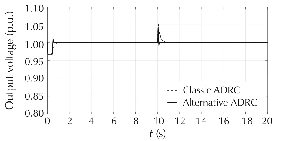
Fig.17 System responses of SVC with positive step disturbance.

Fig.18 Control efforts with positive step disturbance.

Fig.19 Random disturbance.

Fig.20 System responses of SVC with random disturbance.

Fig.21 Control signals with random disturbance.
5 Conclusions
The constancy of frequency and voltage is a critical factor in determining the quality of power supply and utilization[2].However,due to the large and small disturbances caused by sudden load changes,transmission system faults,equipment loss and malfunction and so on,the voltage and frequency deviate from their nominal values from time to time.The deviations degrade the performance of power system,and could dangerously lead to blackouts.With its strong robustness against disturbances,the ADRC is a natural fit for the uncertain power system which is constantly subject to step and random disturbances.Particularly,the ADRC only has two tuning parameters which are simple to determine.
One contribution of the paper is successful application of the classic ADRC to two crucial control loops in power systems:voltage regulation(through SVC)and LFC.Although the classic ADRC has been applied to the LFC and SVC individually in literature,it has not been employed to both LFC and SVC before.The classic ADRC effectively drives the ACE to zero.It exhibits superior transient performance to PI controller in LFC.Classic ADRC is a feasible controller for SVC as well.The other contribution of the paper is original development of an alternative ADRC on the SVC.Because the partial model information of the SVC system is available,the alternative ADRC makes use of the known part of the model,and generates reduced controller gains compared to classic ADRC.The reduced controller gains are an attractive option for practical exercises where small gains are easy to implement.Simulation results show that both classic and alternative ADRCs keep the voltage at all buses within ANSI C84.1 limits for SVC.Using the same amount of control efforts,alternative ADRC produces shorter settling time(with step disturbances),and smaller oscillations(with random disturbances)than classic ADRC in the output of SVC.Frequency domain analyses demonstrate the stability and robustness of the two ADRCs against disturbances and system uncertainties.
In the future,we plan to consider the nonlinearities in system models such as the rate limits on valve position,generation rate constraint for governor,the occurrence of switching time bifurcation in a TCR-SVC system,and non-negligible gating transport delay in thyristor susceptance control.We will employ the ADRC to compensate such nonlinearities and test the control system in Simscape Power Systems.
杂志排行
Control Theory and Technology的其它文章
- From flatness,GPI observers,GPI control and flat filters to observer-based ADRC
- Embedded model control:Reconciling modern control theory and error-based control design
- Development of nonlinear disturbance observer based control and nonlinear PID:A personal note
- Active disturbance rejection control:some recent experimental and industrial case studies
- Intelligence evolution for service robot:An ADRC perspective
- Editorial
