Dynamic responses of reinforced concrete beams under double-endinitiated close-in explosion
2018-10-18BinRoLiChenQinFngJinHongZhongxinLiuHengboXing
Bin Ro,Li Chen,b,*,Qin Fng,Jin Hong,Zhong-xin Liu,Heng-bo Xing
a State Key Laboratory for Disaster Prevention and Mitigation of Explosion and Impact,Army Engineering University,Nanjing,Jiangsu Province,210007,China
bSchool of Civil Engineering,Southeast University,Nanjing,Jiangsu Province,210096,China
cTianjin Key Laboratory of Civil Structure Protection and Reinforcing,Tianjin Chengjian University,Tianjin,300384,China
Keywords:Reinforced concrete(RC)beam Close-in explosion Failure mode Dynamic response Double-end-initiation
ABSTRACT The reinforced concrete(RC)structural component might suffer a great damage under close-in explosion.Different from distant explosions,blast loads generated by the close-in explosion are non-uniformly distributed on the structural component and may cause both local and structural failure.In this study,an experimental study was conducted to investigate the dynamic responses of RC beams under doubleend-initiated close-in explosions.The experimental results show that the distribution of blast loads generated by the double-end-initiated explosion is much more non-uniform than those generated by single-point detonation,which is caused by the self-Mach-reflection effects.A 3D finite element model was developed and validated in LS-DYNA by employing the modified K&C model.Intensive numerical calculations were conducted to study the influences of the initiation way,scaled distance and longitudinal reinforcement ratio on the dynamic responses and failure modes of RC beams.Numerical results show that the RC beam suffers greater damage as the cylindrical explosive is detonated at its double ends than the scenario in which the cylindrical explosive is detonated at its central point.RC beams mainly suffer flexural failure and flexure-shear failure under the double-end close-in explosion,and the failure modes of RC beams change from the flexural damage to flexure-shear damage as the scaled distance or the longitudinal reinforcement ratio decreases.The direct shear failure mode is not usually observed in the double-end-initiated explosion,since the intense blast loads is basically concentrated in the midspan of RC beam,which is due to self-Mach-reflection enhancement.
1.Introduction
A growing number of terrorist attacks and accidental explosions have taken place in recent years.Close-in explosion usually seriously damage the structural components and cause significant casualties and property losses.Therefore,the investigation into dynamic responses of building structures under close-in explosion is attracting more and more attention.
There are many definitions about close-in explosion.Enstock and Smith[1]defined the close-in explosion as an explosive charge detonated at a very short range from a structure.Gel'fandetal et al.[2]suggested that the extent of close-in region Rnwas in the range 0<Rn<20r0,where r0was the characteristic dimension of explosive charge.ACSE[3]defines close-in explosion as explosions with a scaled distance of less than 1.2 m/kg1/3.The scaled distance is defined as Z=,where R is the distance between explosive and structure;W is the charge weight of explosive.Different from distant explosions,blast loads generated by close-in explosions are non-uniformly distributed on the structural components and may cause both localized and global failure.Localized failure often takes place in the form of localized punching and spalling,while global failure is typically manifested as flexural failure[4].
Present researches on dynamic responses of building structures are mainly focused on beams,plates,columns and other loadbearing components.Experimental researches on dynamic responses of RC components under blast loads can get true and accurate results,but there are also some problems such as high cost and safety.Schenker et al.[5]carried out a blast test on full-scale concrete slabs.The comparison between concrete slabs protected by aluminum foam and unprotected slabs proved that the aluminum foam material had an effect of lightening the blast load.The damage degrees and failure modes of a series of RC beams under close-in explosion were studied by Zhang et al.[6].Codina et al.[7]carried out an experimental studyondynamic responses of RC columns under close-in blast loading and calibrated parameters of Riedel-Hiermaier-Thoma(RHT)concrete material model.It was firstly added to the LS-DYNAV971R5.10 version.Based on Johnson-Holmquist[8]model,the maximum failure surface,elastic yield failure surface and residual failure surface were introduced to RHT model to control the shear failure surface.Wang et al.[9]carried out an experimental study on the blast resistance of RC slabs under close-in explosion.Spalling with a few cracks in concrete were clearly observed.
Finite element codes are more and more widely applied in the field of analyzing structural behaviors under blast loading with the development of computer technology.Chen et al.[10]conducted numerical analyses on the dynamic responses of the prestressed RC beam subjected to blast loading by utilizing explicit nonlinear finite element software LS-DYNA,and only the distant explosion scenario was assumed.Yan et al.[11]investigated the failure mechanism of RC beams under close-in explosion.A detailed generation process of cracks,spalling of bottom concrete and concrete cover were simulated.A dynamic plastic damage model for concrete was developed and employed by Zhou et al.[12]to study the responses of RC slabs subjected to blast loading.Comparison of numerical results with the experimental results quantified the model's uncertainty on prediction of damage of RC slabs.The popular K&C model concrete model embedded in LS-DYNA was improved by Hong et al.[13]to simulate the local damage and structural responses of RC components under contact or close-in explosion.Cui et al.[14]carried out a numerical investigation into the failure mechanism of RC columns under close-in explosion.A rapid damage assessment method of RC columns was also proposed based on the numerical results.It is obvious that the finite element method is owning the great benefit on simulating local damage of RC structure under close-in explosion.However,because of the lack of accurate loading model of close-in explosion,a large part of computational resource is spent on the calculation of interaction between close-in blast wave and loading components,but not the structural responses.
The theoretical methods often used for the dynamic responses of RC structural components are the equivalent single degree of freedom(SDOF)method and the modal approximation method,etc.[15].Krauthammer et al.[16,17]analyzed the responses of the roof of RC box-structure under blast loads with the Timoshenkobeam theory.The complete distribution of the dynamic deflection,the dynamic shear and bending moment along the roof span were obtained.Chen et al.[18]developed a new analytical method based on the static membrane action theory to study the dynamic responses of restrained RC structures subjected to blast loads.The analytical results show that the dynamic resistance capacity increase with increasing load rate and restraint stiffness and with decreasing reinforcement ratio.Incorporating an elastoviscoplastic rate-sensitive model into the equivalent SDOF system,Chen et al.[19]proposed a new analytical method to investigate the dynamic responses of partially prestressed concrete beams subjected to blast loads,on base of the layered-section method.However,the failure mechanism of structural components is very complex as it can be affected by many factors.Actually,the theoretical method is not accurate enough to predict the local damage of structural components under close-in explosions.
Although previous researches have made great progress in the analysis of structural components under close-in explosion,there are still many improvements that can be made in this field.Most experimental studies mainly focused on the dynamic responses of structural components,but ignored the non-uniform distribution of blast overpressures on the attack surface.In addition,the explosives were usually detonated at single point in most studies and the influence of initiation way on the dynamic responses of RC structural components was not considered.
In this study, field experiments were carried out to investigate the dynamic responses of RC beams under double-end-initiated close-in explosions,and the blast overpressures distributed on the attack surfaces of RC beams were measured.A FE model was developed in LS-DYNA to analyze the influence of initiation way,scaled distance and longitudinal reinforcement ratio on dynamic responses of RC beams.The modified K&C model proposed by the authors[13]was employed into the FE model to simulate the behaviors of concrete in the numerical simulation.
2.Experimental program
2.1.Mechanism of the Self-Mach reflection
Double-end-initiation of the explosive cylinder usually induces a local enhancement of blast loads due to self-Machreflection [20].Fig.1 shows the mechanism of self-Machreflection with cylindrical explosive initiated at its double ends.Two curved shock wave fronts impinge against each other during propagation after initiating simultaneously at both ends of cylindrical charge.In generally,the collision between the two similar shocks wave front can be considered as a reflection against the rigid face which is denoted as y-axis.The regular reflection takes place as the incident angle is smaller than the critical angleα.However,the Mach reflection occurs as the incident angle is larger than the critical angleα,which is called self-Mach-reflection.When the self-Mach-reflection takes place,the incident shock wave and reflected shock wave converge at a point and form the enhanced Mach wave.
2.2.Preparation of the specimen
Three RC beams designated as B1,B2 and B3 were tested in the experiment.The details of the RC beams loaded in the test are shown in Fig.2.The tested beams are 2500 mm long with the square cross section of 200×200mm2.The longitudinal reinforcing bars are HRB335 grade with a diameter of 20 mm.The transverse reinforcing bars are HRB235 grade with a diameter of 8mm,and the even spacingof transverse bars is 150 mm.The longitudinal reinforcement ratio and transverse reinforcement ratio is 1.90%and 0.35%[21,22],respectively.The concrete is C40 grade and the concrete cover depth for the reinforcing bars is 25 mm.The experimentally measured mechanical properties of reinforcing bars and concrete are shown in Table 1.
2.3.Blast test setup and procedure
Fig.3 shows the loading device of the blast test[23].The tested RC beams were horizontally arranged inside an underground pit with a dimension of 204mm×1500mm×2500mm.And the upper surfaces of tested beams were kept flush with the ground surface.Four rectangular steel blocks with the sectional dimension of 200 mm×100 mm and depth of 20 mm were mounted at both ends of the tested beams,which were constrained by steel bars and steel nuts to fix the tested beams.
In order to measure the blast overpressure time histories on the tested beam generated by double-end-initiated close-in explosion,three PCB B102 series pressure transducers P1,P2 and P3 were set parallel to the top surface of each beam,as shown in Figs.3(c)and Fig.4.The remaining space of pit mouth was filled with the steel plate to avoid the diffraction of blast wave.In addition,three WYJL-300(LVDT)displacement transducers D1,D2 and D3 were mounted on the bottom surface of each beam to record the variation of beam deflection during the explosion,as shown in Fig.4.The WYJL-300 displacement transducer is a kind of electric LVDT sensor with electric resistance of 5KΩ,which was manufactured by Xi'an Xinmin Electronic Technology Co.,Ltd.The measuring range,frequency and working voltage of it are 300 mm,2000 Hz and 12VDC,respectively.
The explosive used in the test was rock emulsion explosive manufactured by Nanjing Changshan Chemical Co.,Ltd.,and the shape of the explosive was cylindrical.The TNT equivalence coefficient of the rock emulsion explosive was determined to be 0.609 by Fan et al.[24].The explosive was hung 1.5 m right above themid-span of the tested beam and was initiated by two detonators at its both ends.Tested beams numbered B1,B2,and B3 were exposed to overpressures induced by emulsion explosives weighting 9.0 kg,13.4 kg and 24.0 kg,respectively.Fig.5 shows the diagram of dimensions of cylindrical explosives.The details of emulsion explosive used in each test are shown in Table 2.
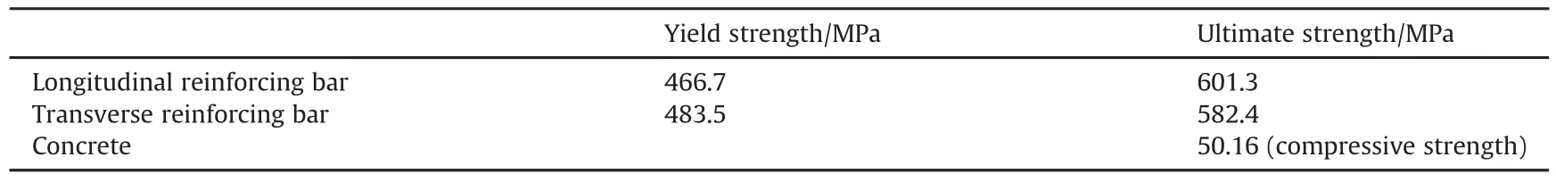
Table 1 Experimentally measured mechanical properties.
2.4.Test results and discussion
2.4.1.Overpressure time histories
The overpressures induced by different charge of explosives applied on the tested beams were recorded by pressure transducers P1,P2,and P3,whose locations are presented in Fig.4.And the overpressure time histories recorded by pressure transducers in the blast test are presented in Fig.6.The distances from point P1,P2 and P3 to the orthographic projective point of the explosive on the attack surface are 760 mm,380 mm and 0mm,respectively.It is generally found that the intense blast loads are concentrated in the mid-span of RC beams.When the emulsion explosive charge is 9.0kg,the test peak overpressure at P3 is 34.24MPa,which is 4.8 times larger than that at P1,i.e.,5.91 MPa.When the emulsion explosive charge is 13.4kg,the test peak overpressure at P3 is 24.20 MPa,which is about 1.7 times larger than that at P1,i.e.,9.07MPa.When the explosive charge is 24.0 kg,the peak overpressures at P2 and P3 exceed 70MPa and 35MPa,respectively,however,overrun the measuring range of pressure transducers.It could also be estimated that the peak overpressure at P3 point is at least about 5 times larger than that at P1.The peak reflected overpressures calculated by Conwep[25]that assumes the charge to be spherical and initiated at its central point are also exhibited in Fig.4.In comparison,the reflected peak overpressures at P3 calculated by Conwep are basically about 50%larger than that at P1 in three scenarios,however,the concentrative degree of blast loads is much lower than those in the corresponding testing scenarios.It could be concluded that the blast loads generated by the doubleend-initiated close-in explosion are highly centralized in a close range around the orthographic projective point of the explosive on the attack surface,which is far different from those generated by the central point detonation.The main reason for this phenomenon is that a self-Mach-reflection occurs in the radial direction of cylindrical explosive and enhances the overpressure significantly.
2.4.2.Damage and crack pattern
Fig.7 shows the damage and crack patterns of the tested RC beams after exposure to blast loads.It is obvious that B1,B2 and B3 suffer different degrees of damage,and serious damage is induced by the blast scenario with small scaled distance.Slight concrete fracture and six macro cracks appear on the bottom and side surface of B1 and B2,however,the residual deformation is not significant.In comparison,a large amount of concrete spalling appears at the bottom surface of B3,as well as much more cracks also can be found around B3.The damage of B3 are the most serious.All the concrete cover for the reinforcing bars near the left support of B3 has fallen apart,and numbers of large cracks propagate through the core concrete.It can also be found that only a little concrete on the upper surface of both B1 and B2 has crushed,while a much larger area of concrete at the middle part of the upper surface of B3 has also been crushed.In addition,significant residual deformation could be found on B3 after explosion.
2.4.3.Displacement time histories
The displacement time histories at three transducers,D1,D2 and D3,of tested beams are plotted in Fig.8.It is generally accepted that the displacement response decreases from mid-span,D3,to the end,D1.Compared with B1,the maximum displacements at D1,D2 and D3 of B3 increase 291.8%,316.6%and 393.2%,respectively,from 14.49 mm,27.26 mm and 34.84 mm-56.77mm,113.57 mm and 171.83 mm.As for the residual deformation,the residualdisplacements at D1,D2 and D3 of B3 increase 663.2%,719.8%and 931.0%, respectively, from 5.03 mm, 9.75mm and 11.76mm-38.39 mm,79.93 mm and 121.25 mm.It is still valid in the double-end-initiated close-in explosion that the maximum displacement and residual displacement of the beam increase with the charge weight when the stand-off distance is maintained.

Table 2 Details of the emulsion explosive.
3.Numerical analysis
3.1.Finite element model and boundary condition
A FE model was developed in the commercial software LSDYNA,as shown in Fig.9.The 8-node solid element(SOLID_164)and 3-nodes beam element(BEAM_161)were utilized to model concrete and reinforcement,respectively.Four rigid blocks to restrain double ends of the beam were also modeled by using the solid element(SOLID_164).The fine mesh size determined in this FE model for concrete and steel reinforcing bars is 12.5 mm and the total number of elements is 55376.The nodes that both concrete and reinforcing bars shared were merged up to simulate a full bonding relationship.
As for the boundary condition,*AUTOMATIC_SURFACE_TO_-SURFACE was employed to model the frictional contact between the concrete and the rigid blocks.The nodes of the upper surface of the upper rigid block and the bottom surface of the lower rigid block were constrained in all directions.
3.2.Material model
In LS-DYNA,there are many material models that can be used to simulate the behavior of concrete material such as*Mat Johnson Holmquist(MAT_111)[26],*Mat CSCM Concrete(MAT_159)[27],*Mat_Winfrith_Concrete(MAT_084)[28],*Mat Concrete Damage Rel3(K&C)[13],etc.Among these material models,the K&C and CSCM model are usually employed to describe concrete behavior under blast or impact loads.In this study,the modified K&C model proposed by the authors[13]was utilized.
Three modifications were employed in the modified K&C model,i.e.tensile damage accumulation,relationship between yield scale factor and damage function and tensile DIFt.
In the original K&C model,the tensile damage accumulation is determined as follows,
Experiments from instrumented spalling tests[29]showed that the fracture energy increases with the strain rate,which was taken into consideration in the proposed model.The damage accumulation was modified as follows,
where dλis tensile damage accumulation;is the effective plastic strain increment;p is pressure;b2is damage constant;ftis tensile strength of concrete.
The original(1+p/ft)was changed to (1-p/ft)in Equation(2).This is because that the value of(1+p/ft)could be very small when the pressure is close to-ft,which usually causes numerical instability.This modification makes that the tensile damage function is identical to the compressive damage function.Another modification is that the factor rfwas excluded to make it more convenient and clear to describe the general relationship of fracture strain and fracture energy with strain rate revealed in the tests[29].
In the original K&C model,the relationship between yield scale factorηand damage functionλis automatically generated,benchmarked with limited specimens.The parameterηandλwas respectively determined with the uniaxial compression stressstrain relationship σ11- ε11of concrete in the modified model,
whereηis yield scale factor;Δσis failure surface for the deviatoric stresses;Δσmis maximum stress difference;Δσyis yield surface for the deviatoric stresses;σis stress;fcis compressive strength of concrete.
where dλis tensile damage accumulation;γis failure surface for the deviatoric stresses;rfis the strength dynamic increase factor;p is pressure;b1is damage constant;ftis tensile strength of concrete;ω is the fractional dilatancy.
Different from the static scenario,the strain rates of the engineering material under blast or impact loads are much higher up to 102~103s-1.Thus,the mechanical properties of strain-rate dependent materials can be significantly enhanced at high strain rates.The increment of material strength at high strain rate could be described by the relationship between the dynamic increase factor(DIF)and the strain rate,i.e.,the ratio of dynamic-to-static strength versus strain rate[10].
The third modification was that the empirical formula proposed by Xu[30]was adopted to replace that proposed by Malvar[31]in the original K&C model to calculate dynamic tensile strength increase factor DIFt of concrete.The empirical formula is expressed as
where˙ε0=1s-1,Fm=10,Wx=1.6,S=0.8 and Wy=5.5.
In this study,the DIF of concrete compressive strength was defined with the formula proposed by Model Code 2010[32],as shown in Eqs.(6)and(7).
where fcis the dynamic compressive strength at strain rate˙ε;fcsis the quasi-static compressive strength at˙εcs;logγ=6.156α-0.49;α =1/(5+3fcu/4);fcuis the static cube compressive strength in MPa.
The DIF of reinforcing barsgiven by Malvar[31]was employed in this study,as described in Eq.(8)and Eq.(9),
where fyis the yield strength of steel in MPa;fysis the quasi-static yield strength of steel in MPa;DIF is constant when˙ε≥200s-1.
The*Mat Plastic Kinematic(MAT_003)material model which is able to describe isotropic and kinematic hardening plasticity was employed to model the behavior of longitudinal reinforcing bars and stirrups.This material model is available for beam,shell,and solid elements.The material model*MAT_RIGID(MAT_020)was utilized to model the behavior of rigid blocks at beam ends.
The keyword card*Mat Add Erosion was employed to describe the physical fracture or crushing of concrete.In this study,the principal strain was chosen as the failure criteria.According to Luccioni et al.[33],the maximum principal strain at failure for concrete varies a lot in different numerical studies.The maximum value can be 0.15 and the minimum value can be 0.01.The maximum principal strain at failure for concrete in our study was adjusted between 0.01 and 0.15 with the gradient of 0.01.When the value was 0.03,the damage and crack patterns of FE models was similar to those of tested RC beams.Thus,the maximum principle strain for concrete was empirically set at 0.03.
3.3.Blast loading model
Different from external distant explosion,the overpressures generated by the double-end-initiated close-in explosion is highly non-uniform and may cause both local and structural failure to structure components.AUTODYN is an explicit finite element program that can be used to analyze nonlinear dynamic behavior of solid, fluid and gas.Based on the testing data and the calculation results in AUTODYN,the authors[20]proposed a blast loading model on the beam-like component,where the cylindrical explosive was initiated at its double ends and the scaled distance was within the close-in range.Therefore,the proposed blast loading model was employed in this calculation.
The distribution of blast loads on the attacking surface of the beam was simplified,as shown in Fig.10.It was assumed that the overpressure within the range of half the distance from the adjacent pressure transducer is constant,and its amplitude is the same as that of the central pressure transducer.
The empirical formulas to determine the overpressure pressure time history given by the authors[20]are presented as follows,
where Ps0is the peak reflected overpressure;t0is the duration time of positive overpressure;θis the decay coefficient;;Z is the scaled distance;D and L are the diameter and length of cylinder explosive,respectively;A1,A2,A3,B1,B2,B3,C1,C2,C3are all constants empirically determined by the authors[20].
The empirically determined constants A1,A2,A3,B1,B2,B3,C1,C2,C3are presented in the following Tables 3-5.
The comparisons of calculated overpressure time histories withexperimental overpressure time histories are shown in Fig.11.It can be seen from Fig.11 that the calculated overpressure time histories by the simplified blast loading model show good agreement with the experimental data.
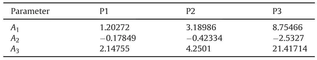
Table 3 Constants of peak reflected overpressure Ps0.
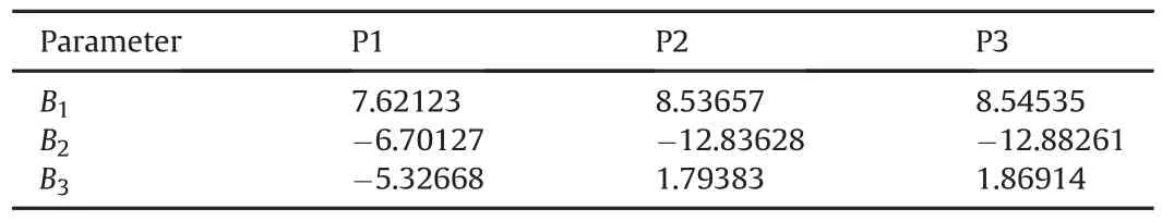
Table 4 Constants of positive duration time t0.
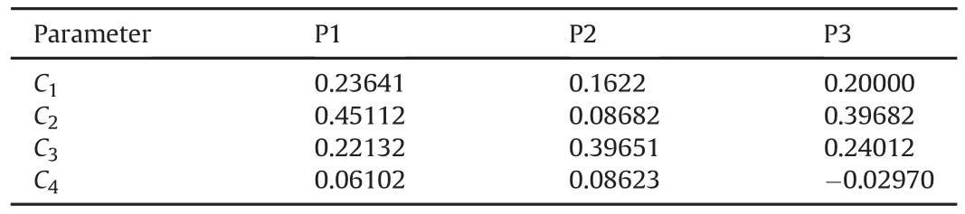
Table 5 Constants of decay cofficient θ.
3.4.Validation of the finite element model
Comparisons of displacement time histories between the test data and FE results are plotted in Fig.12.It is obvious that the FE results basically agree well with the test data.It can also be found that the free oscillation periods and oscillation amplitudes predicted by the FE model are a little smaller than the test data after loading.This difference was mainly attributed to the simplification of boundary condition.Because the rigid blocks were assumed to be completely fixed in FE model,but its outward movement in the direction of beam length could not be constrained by the bolts in the field test.In addition,the unexpected elastic deformation of steel bars and steel nuts was not considered in the FE model.
Fig.13 shows the comparison of damage morphologies of RC beams between the in-situ test and the FE calculation.It is found that the predicted failure modes of B1,B2 and B3 by the FE model agree well with the in-situ observations.The damage degree of the RC beam increases significantly with the scaled distance decreasing from 0.85 to 0.61.In addition,the test beam B1 and B2 mainly suffer a little flexural deformation,while beam B3 suffers flexural damage as well as serious shear damage.
4.Parametric discussion
4.1.Initiation way
The initiation way of explosive has a significant effect on the propagation of blast wave it generates[34].With differences from the common single point initiation,double-end-initiation of cylindrical explosive inevitably results in a local enhancement of blast loads due to the self-Mach-reflection of blast wave[20].Therefore,dynamic responses of structural components vary from each other as the initiationway varies.The differences of dynamic responses of the RC beam with cylindrical explosive initiated at its central point and the RC beam with cylindrical explosive initiated at its double ends are discussed in this section.The construction details of the calculated RC beam in this section were the same as the tested specimen described in section 2.1.
The overpressures and distribution of blast loads applied on the attack surface of the calculated RC beam with cylindrical explosive initiated at its double ends were determined by the blast loading model described in section 3.4.The distribution of blast loads on the attack surface of the RC beam with cylindrical explosive initiated at its central point was assumed as for the double-endinitiation(Fig.10).However,the overpressures were adopted from Ref.[20]as calculated by the authors.Fig.14 presents the determined overpressure time histories of P1,P2 and P3 under central-point-initiation and double-end-initiation,respectively.The diameter-length ratio and the scaled distance were 0.4 and 0.4 m/kg1/3,respectively.It can be found that the peak overpressure at P3 generated by double-end initiation is 146.99 MPa,which is 2.2 times of that generated by central-point initiation.In addition,the peak overpressure at P3 by double-end initiation is 7.3 times larger than that at P1,while the peak overpressure at P3 by central-point initiation is just 2.2 times larger than that at P1.It also proves that the blast loads generated by the double-end-initiated close-in explosion are highly centralized in a close range around the orthographic projective point of the explosive on the attack surface,and the overpressures are dramatically enhanced compared to the central-point-initiated close-in explosion.This is because a self-Mach-reflection occurs in the radial direction of the double-endinitiated cylindrical explosive,and as a consequence of which,the overpressures are significantly enhanced.
Fig.15 shows the comparisons of the calculated displacement time histories under two initiation ways.It is found that both the calculated RC beams have residual deformation after detonation.The maximum displacements at D1,D2,and D3 by double-end initiation are 145.81 mm,284.05mm and 377.23mm,which are respectively 59.6%,62.5%and 63.7%larger than those by centralpoint initiation,i.e.,91.34 mm,174.81mm and 230.38 mm.The residual displacements at D1,D2,and D3 by double-end initiation are 76.69mm,158.69 mm and 196.49mm,which are 56.3%,64.2%and 61.7% larger than those by central-point initiation,i.e.,49.07 mm,96.65 mm and 121.52 mm.This indicates that the overpressures induced by double-end-initiated close-in explosion may cause much more serious damage to the calculated RC beam than central-point-initiated close-in explosion.
Equivalent plastic strain contours in concrete under two initiation ways are exhibited in Fig.16.It is obvious that the beam suffered much more macro cracks under double-end initiation than that under central-point initiation.Flexure-shear damage can be found in both RC beams,while the risk for shear failure of the beam under central-point-initiated explosion is greater.The reason for the difference is that the double-end-initiated close-in explosion leads to more centralized distribution of greater blast loads on the RC beam than central-point-initiated close-in explosion.It also indicates that the direct shear failure is rarely observed in the double-end-initiated explosion,since the intense blast loads is basically concentrated in the mid-span of RC beam,which is due to the self-Mach-reflection enhancement.
4.2.Scaled distance
Scaled distance is another factor that affects the blast loads explosive generates,even in the double-end-initiated close-in explosion,and in turn affect dynamic responses of RC structures.In this section,the other parameters were kept unchanged as the influence of scaled distance was discussed.The construction details of the calculated RC beam in this section were the same as the tested specimen presented in section 2.2.The blast loads generated by double-end-initiated close-in explosion applied on the calculated RC beam were also determined by the blast loading model described in section 3.4.The diameter-length ratio of the cylindrical explosive was determined as 0.4 and the scaled distances were 0.4m/kg1/3,0.6m/kg1/3,and 0.8 m/kg1/3,respectively.
Comparisons of maximum displacements and residual displacements of RC beams under double-end-initiated explosion with different scaled distances are shown in Fig.17.The maximum displacements at D1,D2 and D3 decrease about 91.8%,92.2%and 92.5%,from 141.82 mm,284.05mm and 377.23 mm-11.68 mm,22.94 mm and 28.13 mm,respectively,as the scaled distance increases from 0.4 m/kg1/3to 0.8 m/kg1/3.In addition,the residual displacements at D1,D2 and D3 decrease 94.3%,94.5%,and 94.0%from 76.69mm,158.69 mm and 196.49mm-4.34 mm,8.75mm and 11.78mm,respectively,as the scaled distance increases from 0.4m/kg1/3to 0.8 m/kg1/3.
Fig.18 shows the equivalent plastic strain contours of RC beams as the scaled distance varies.Serious concrete fracture and many macro cracks can be seen in the RC beam as the scaled distance is 0.4m/kg1/3and 0.6 m/kg1/3.However,just a small amount of macro cracks can be observed in the RC beams as the scaled distances is 0.8m/kg1/3.In addition,slight concrete spallation appears at the bottom surface near the mid-span of the beam as the scaled distance is 0.4 m/kg1/3.The RC beam suffers flexural damage as the scaled distance is 0.8 m/kg1/3,while flexure-shear damage as the scaled distance is 0.4m/kg1/3and 0.6m/kg1/3,respectively.And the RC beam suffers the most severe damage as the scaled distance is 0.4m/kg1/3.It could be concluded that the failure modes of RC beams change from flexural damage to flexure-sheardamage as the scaled distance decreases,which is similar to distant explosions.
4.3.Longitudinal reinforcement ratio
The other parameters were kept unchanged as the influence of the longitudinal reinforcement ratio was discussed.The blast loads generated by the double-end-initiated close-in explosion applied on the calculated RC beam were also determined by the blast loading model described in section3.4.The diameter-length ratio of the cylindrical explosive and the scaled distance were determined as 0.4 and 0.5m/kg1/3,respectively.The longitudinal reinforcement ratio was changed by adjusting the diameter of longitudinal reinforcing bars,which was set at 10 mm,30 mm and 50 mm,respectively.And the corresponding longitudinal reinforcement ratios were 0.48%,4.65%and 13.83%,respectively.The other construction details of the calculated RC beam were the same as the tested specimen described in section 2.2.
The maximum displacements and residual displacements of the beam with different longitudinal reinforcement ratios are shown in Fig.19.It could be found that the maximum dis placements at D1,D2 and D3 decrease about 82.1%,82.2%and 82.7%,from 136.87 mm,281.98 mm and 334.83 mm-24.52 mm,50.09 mm and 57.84 mm,respectively,as the longitudinal reinforcement ratio increases from 0.48%to 13.83%.The residual displacements at D1,D2 and D3 decrease 80.1%,82.0%and 79.4%,from 90.09 mm,197.73 mm and 228.4 mm-17.91 mm,35.62mm and 47.02 mm,respectively,as the longitudinal reinforcement ratio increases from 0.48%to 13.83%.It indicates that the blast-resistant capacity under close-in explosion would be improved by increasing the longitudinal reinforcement ratio.
Equivalent plastic strain contours of RC beams with different longitudinal reinforcement ratios are presented in Fig.20.It is obvious that the RC beams with the longitudinal reinforcement ratio of 0.48%and 4.65%suffer flexure-shear deformation,while the beam with longitudinal reinforcement ratio of 13.83%mainly suffers slight shear fracture in concrete.With the largest amount of macro cracks and the maximum plastic deformation,the calculated beam with the longitudinal reinforcement ratio of 0.48%suffers the greatest degree of damage.It can also be concluded from Fig.20 that the damage degree of the RC beam increases with the decreasing of longitudinal reinforcement ratio.
5.Conclusions
Experimental and numerical investigation into the dynamic responses of RC beams under double-end-initiated close-in explosion were conducted in this study.Parametric discussion was carried out to study the influences of initiation way of cylindrical explosive,scaled distance and longitudinal reinforcement ratio on the dynamic responses of RC beams.Conclusions obtained from this study are listed as follows.
(1)The field blast test illustrates that the blast loads generated by the double-end-initiated close-in explosion are highly centralized in a close range around the orthographic projective point of the explosive on the attack surface.Due to the self-Mach-reflection in the radial direction of cylindrical explosive,the overpressures generated by the double-end initiated close-in explosion are significantly enhanced and highly centralized.
(2)The initiation way of cylindrical explosive has a significant effect on the dynamic responses of RC beams.The RC beam suffers obviously more serious damage under double-end close-in explosion than central-point initiation owing to the self-Mach-reflection enhanced blast loads.Due to the high centralized distribution of blast loads generated by the double-end close-in explosion,RC beams mainly suffer flexural failure and flexure-shear failure.The direct shear failure is rarely observed under double-end-initiated explosion.In addition,the risk for shear failure of the beam under double-end-initiated explosion is lower than that under central-point-initiated explosion.
(3)As with other blast loading types,the scaled distance significantly affects the dynamic responses of RC beams exposed to double-end-initiated close-in explosions studied here.The deformation and damage degree of the RC beam increase dramatically as the scaled distance decreases from 0.8 m/kg1/3to 0.4 m/kg1/3.In addition,the failure modes of RC beams change from flexural damage to flexure-shear damage as the scaled distance decreases from 0.8m/kg1/3to 0.4m/kg1/3.
(4)The dynamic responses of RC beams can also be affected by the longitudinal reinforcement ratio.The displacement responses and damage degree of the RC beam decrease significantly as the longitudinal reinforcement ratio increase from 0.48%to 13.83%.
Acknowledgements
This work is supported by the National Natural Science Foundations of China(Nos.51622812,and 51427807),National Basic Research Program of China(No.2015CB058003)and China Postdoctoral Science Foundation(No.2017M613379).
杂志排行

Defence Technology的其它文章
- Overview of Al-based nanoenergetic ingredients for solid rocket propulsion
- Implications of fine water mist environment on the post-detonation processes of a PE4 explosive charge in a semi-confined blast chamber
- Systematic research on the performance of self-designed microwave plasma reactor for CVD high quality diamond
- cis-1,3,4,6-Tetranitrooctahydroimidazo-[4,5-d]imidazole(BCHMX)as a part of explosive mixtures
- Joining and machining of(ZrB2-SiC)and(Cf-SiC)based composites
- Structural evolution,optoelectrical and corrosion properties of electrodeposited WO3integration on Zn-TiO2electrolyte for defence super application