基于螺旋贝壳仿生的发动机增压器涡轮蜗壳设计提升涡轮性能
2018-10-11张克松王希波马云海
吴 娜,张克松,王希波,马云海
基于螺旋贝壳仿生的发动机增压器涡轮蜗壳设计提升涡轮性能
吴 娜1,张克松1,王希波1,马云海2※
(1. 山东交通学院汽车工程学院,济南 250357;2. 吉林大学工程仿生教育部重点实验室,长春 130022)
增压器蜗壳性能直接影响增压器整体效率和性能。通过降低蜗壳内腔流动阻力、减少蜗壳能量损失对提高增压器效率和性能具有重要意义。海洋螺旋形贝壳在进化过程中形成了减少流体阻力、降低运动过程中流体能量损耗的结构特征。该文以螺旋贝壳为仿生原型,通过逆向工程技术获取贝壳内腔数据,在几何分析的基础上提取内腔截面部分数据作为仿生蜗壳设计原始数据,并完成数学建模。通过数据优化得到增压器涡轮蜗壳仿生设计截面曲线,实现蜗壳仿生曲面设计。建立原型增压器和仿生增压器计算模型,在原型增压器仿真模型与台架试验吻合较好的条件下,采用流体力学软件对原型及仿生优化增压器涡轮效率、流通特性及蜗壳内流态等性能进行仿真分析。结果表明,涡轮流通能力不变情况下,仿生蜗壳使涡轮效率提升3%,最大可提升5%以上;流场分析结果表明,仿生优化蜗壳减小蜗壳壁面附近的流动损失和流道内气流摩擦,壳内流动平稳均匀,无旋流,是涡轮效率明显提高的根源。本文所采用的方法对增压器涡轮性能的提升显著,可以为汽车和农业机械涡轮增压系统设计和优化提供参考和借鉴。
仿生;设计;试验;涡轮蜗壳;涡轮效率;螺旋贝壳;流通能力
0 引 言
涡轮增压器已成为柴油机和汽油机的重要部件。涡轮增压器的使用可以大幅提升内燃机的动力性能和燃油经济性,也是内燃机小型化的关键手段。研究提升增压器性能得到国内外工程人员的重视[1-5]。增压器蜗壳对涡轮和增压器性能有着重要影响[6-9],蜗壳的不同几何设计参数影响蜗壳的曲率变化、蜗壳腔内流体与壁面间的摩擦力及压力梯度分布,改变蜗壳腔内流场分布,影响蜗壳腔内的流体运动规律、压力分布及能量损失,影响蜗壳工作性能[10-13],增压器蜗轮蜗壳流道设计水平对涡轮的效率和流通能力起着关键作用[14-17]。目前还没有成熟的蜗壳流道截面的设计方法,蜗壳结构的优化设计方法还处在不断发展完善中[18-20 ]。
传统增压器蜗壳的设计采用公式计算并修正的方法进行,常用计算方法为周向平均速度法和等环量法。这2种传统设计方法完全依据理论计算得出。尽管设计结果也会根据实验数据进行微调整,但完全依据理论计算的蜗壳设计方法单一,且阻碍了蜗壳设计技术的快速发展。
仿生设计通过对生物结构、生物功能和生命过程的认识为解决工程和机械设计中的难题提供巧妙的设计思路和灵感[21-25]。采用仿生技术进行涡轮蜗壳设计可实现蜗壳设计技术的创新和发展。螺旋贝壳是软体动物的保护外套,在亿万年的进化过程中,已进化出适应海洋生存,减小流动摩擦阻力的宏观流线形结构和形体,这为增压器蜗壳设计提供了新的思路和方法。本文以螺旋贝壳为研究对象,采用仿生学方法对现有增压器涡轮蜗壳进行优化设计,采用数值模拟方法对优化前后的涡轮结构进行全面分析研究,对比研究仿生蜗壳性能。
1 仿生增压器涡轮蜗壳设计
1.1 螺旋贝壳内腔截面轮廓线建模
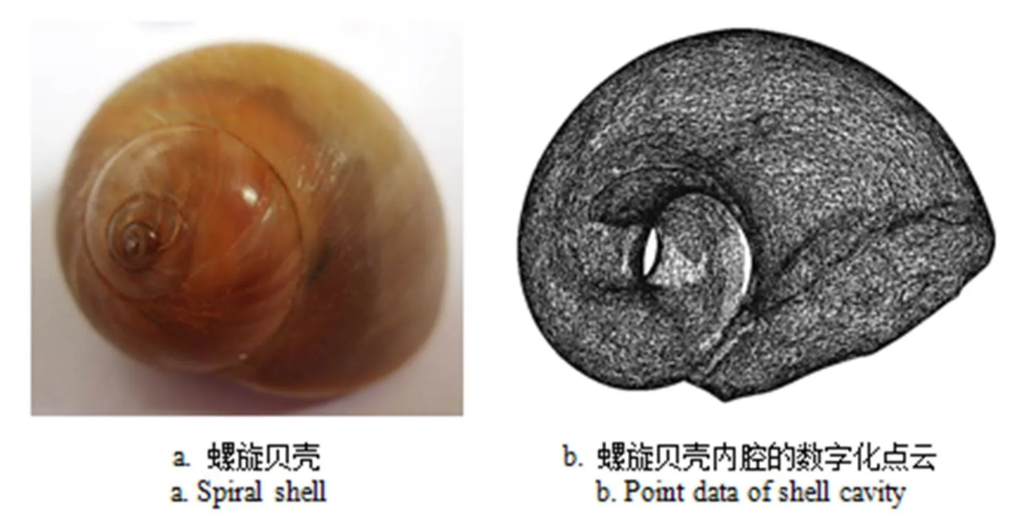
螺旋贝壳如图1a所示。利用逆向工程技术,获取螺旋贝壳内腔的数字化点云如图1b所示。考虑到增压器蜗壳入口和出口的比值大小直接影响增压器整体效率,由螺壳大端入口按螺旋方向取其270°内的螺旋贝壳曲面模型,过螺壳正投影圆心均角度依次截取16个截面,角度间隔18°,如图2a所示。螺壳内腔截面轮廓线形状如图2b所示。对第1条截面轮廓曲线进行几何特征分析,结合增压器蜗壳流道设计原理,提取轮廓线的曲率变化均匀、流线型较好的部分数据点云,拟合处理后作为蜗壳流道截面设计的部分基准轮廓线(如图2b所示)。将曲线在数学分析软件中进行几何特征分析可知,点云拟合曲线是长轴为17.54,短轴为14.18椭圆的一部分。

图1 螺旋贝壳和内腔点云
采用最小二乘法完成曲线数学建模。曲线数学模型方程为

通过曲线镜像获得增压器仿生蜗壳通道最大截面几何形状如图2c所示,其形状类似水滴形。依次处理获得其余15条螺壳内腔截面轮廓部分曲线,数学模型如表1所示,其中。软件镜像处理后获得增压器涡轮蜗壳流道截面设计曲线。

表1 螺壳内腔截面部分轮廓曲线的数学模型
1.2 仿生增压器涡轮蜗壳设计
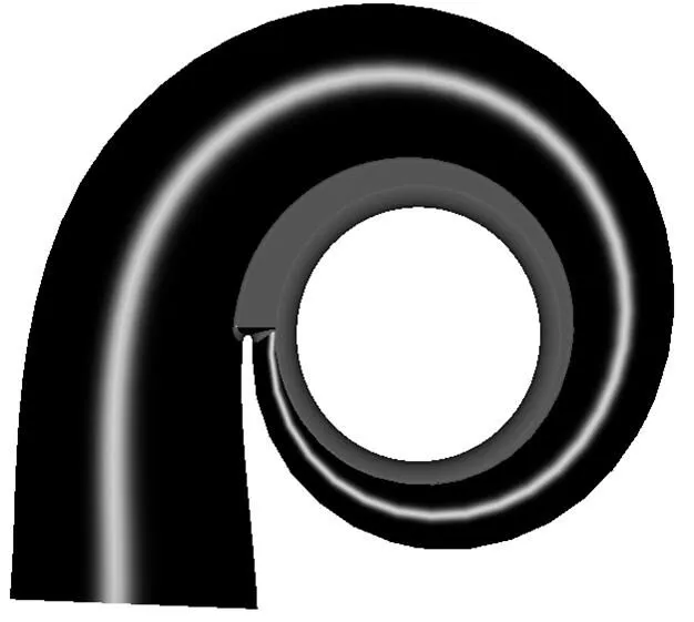
将获得的截面曲线依据面积由小到大的次序沿360°圆周向展开排列,作为增压器蜗壳流道设计的截面线,每个截面线分隔间距为22.5°,具体形式如图3所示。以16条截面轮廓线为基础数据实现增压器涡轮蜗壳的曲面设计,蜗壳流道出口处曲面与蜗壳通道曲面相切过渡,将造型曲面依据实际增压器涡轮蜗壳厚度进行加厚处理,实现仿生增压器涡轮蜗壳流道设计,如图4所示。

图3 蜗壳流道截面仿生设计曲线

图4 仿生蜗壳设计模型
2 仿生增压器涡轮蜗壳性能仿真分析
本文以某型排量1.5 L的车用汽油机用增压器为研究对象,采用数值模拟方法分析常用工况范围内原型蜗壳和仿生设计蜗壳的性能差异。首先以原型蜗壳建立数值模型,并验证其可靠性。然后以原型蜗壳为基础,匹配仿生蜗壳。在常用工况范围内对仿生蜗壳和原型蜗壳进行数值仿真,并从微观流场探索两者差别,从而实现对增压器蜗壳的优化。
2.1 仿真模型建立
原型蜗壳与仿生蜗壳的三维建模结构如图5所示。建模过程中2个增压器蜗壳/保持一致,蜗壳出口宽度与出口直径保持一致。仿真模拟中涡轮形式采用全轮盘向心径流式结构,叶片数为11片,进口直径为37 mm,出口直径为32.1 mm,值为12.56 mm,相应压气机叶轮直径为44.2 mm,蜗壳喷嘴宽度4.8 mm。

图5 原型与仿生蜗壳结构对比
仿真数学模型采用雷诺时均N-S方程组[26],选用RNG方程模型。计算域分为蜗壳进口延长段、蜗壳、转子和涡轮出口延长段共4个域,转子区域采用结构化网格,在叶片周围添加O型结构网格;而蜗壳由于流道造型复杂,采用非结构网格;在涡轮和蜗壳的各个壁面附近均添加了附面层网格[26],2种结构的蜗壳在划分网格时采用同样的网格参数和方法。仿真模拟中,共用的涡壳进口延长段、转子区域和涡轮出口延长段的网格单元数分别为119 595,2 769 008和116 085;原型涡壳网格数为752 431,仿生涡壳的网格数为784 168,仿生涡壳由于和原型涡壳保持相同的值而增大了流道截面,其网格总数比原型涡轮模型多3.1万。
蜗壳和出口延长段设定为静止域,转子部分设定为旋转域,流体域之间用冻结交接面连接。模型壁面均设定为光滑、无滑移、绝热的状态,流体定义为理想气体,流体粘度设置为温度的函数,各物性参数根据试验数据查表而得[27]。模拟计算中,2种蜗壳所匹配的涡轮转子域完全相同。
2.2 数值仿真模型验证
数值仿真模型的试验验证在QYZ-2型增压器试验台进行,如图6所示。图6a为试验台照片,图6b为试验台工作流程图。压气机进口流量采用双纽线流量计测量,最大测量误差小于2%FS。压气机入口和出口均设有有压力传感器和温度传感器,涡轮进口处设置有有涡轮进气压力和进气温度传感器,涡轮出口的延长管道中有涡轮排气压力和排气温度传感器。压力传感器最大误差小于2.5%FS,温度传感器最大误差小于3%FS。
高压气源的空气经过燃烧室的加热达到试验设定的涡轮进气温度,燃烧室的燃油为柴油。涡轮流量等于压气机流量加上燃油流量。试验时,增压器转速误差控制在±200 r/min,在增压器工作工况稳定3 min后通过数据采集器同时采集所有相关参数。

图6 增压器试验台及结构原理图
验证试验以原型蜗壳进行,对比在相同转速、相同进口绝对压力和进气温度条件下,试验流量和模拟流量。选取12×104、16×104和20×104r/min作为典型工况点进行验证,3个工况对应的蜗壳进口绝对压力、温度、实测流量和模拟仿真得到的流量如表2所示。
对比表2中实测流量与模拟流量,可以发现在中、低转速工况下,模拟和试验吻合较好;而在高转速工况下,模拟值与试验值相差略大,最大误差为2.68%。这与模型的简化、试验传感器精度、测量不确定性等因素有关[28-29]。总体而言,模拟计算的最大误差在允许范围内,认为仿真模型与试验吻合较好,模型具有较好的可靠性,可以满足后续研究的要求。

表2 原型蜗壳的模拟计算和试验对比
3 原型蜗壳与仿生蜗壳仿真结果分析
对2种蜗壳进行典型工况的模拟计算,选择12× 104、16×104和20×104r/min三个转速,分别代表涡轮运行的低中高转速。模拟计算后,对所涉及的工况进行宏观性能分析,评价参数为涡轮效率、流通特性和蜗壳总压损失系数。
3.1 涡轮效率分析
涡轮效率是评价涡轮工作性能的最重要参数之一。两种蜗壳对涡轮效率的影响如图7所示。在不同转速工况下,随着膨胀比的增加,涡轮效率先增大而后减小。转速越低,涡轮效率变化越快。
由效率对比分析可知,所有工况下,配有仿生优化蜗壳的涡轮效率均高于原型蜗壳的涡轮效率,2种情况下涡轮效率差值均在1.3%以上。固定转速条件下,涡轮进口压力越小,两者效率的差值越大;在中低转速工况下,普遍相差3%以上。涡轮转速越低,效率差值越大,当转速为12×104r/min、进口膨胀比为1.2的工况时,效率最大差值为5.56%。这些趋势说明,相对原型蜗壳,仿生优化蜗壳不但效率高,而且在低工况时明显提升了涡轮效率。中低转速工况下普遍提升3%以上,最大提升效率5%以上。这有利于增压器改善发动机的换气情况,特别是低速工况,有效改善废气涡轮增压器低速响应特性,从而提升发动机低速扭矩和加速性能,有利于改善车辆的燃油经济性能和动力性能。

图7 仿生蜗壳与原型蜗壳的涡轮效率对比
3.2 涡轮流通特性分析
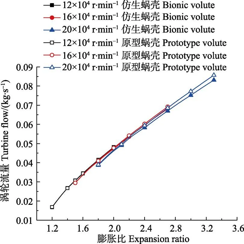
2种蜗壳对涡轮流通特性的影响如图8所示。随着膨胀比的增加,涡轮流通能力增加,对应变化关系基本呈线性关系。涡轮流通能力受转速的影响较小,在中低转速工况下,涡轮的流量曲线基本重合,在20×104r/min高转速的高膨胀比工况时,仿生优化蜗壳的涡轮流量略小于原型蜗壳,但没有明显差别,其流通特性基本相同。
3.3 流场分析
当仿生涡轮的流通能力与原型涡轮基本保持一致情况下,涡轮效率有了明显的提升。涡轮效率提升的主要原因是涡轮流场的优化。由图7可知,20×104r/min时涡轮虽具有最高效率点,但是效率曲线的最高点不在同一工况点,仿生蜗壳和原型蜗壳的涡轮最高效率点分别对应的膨胀比为2.1和2.3,所以流场分析选取转速为16× 104r/min、膨胀比为1.8的工况进行。

图8 仿生蜗壳与原型蜗壳的涡轮流量特性对比图
图9为原型和仿生蜗壳周向90°~220°范围内的轴向截面上的速度矢量分布。原型蜗壳在流道喷嘴出口附近出现2个气流回旋涡,说明蜗壳内部有螺旋滚流,在上下壁面附近气流的影响下,上下回旋涡的旋向相反,产生混流现象。蜗壳流道中产生的气流螺旋滚流使得蜗壳内部流动特性变差,增加混流损失,影响涡轮叶轮内部的流动,降低了涡轮总体效率。而优化后的蜗壳流道内部的气流则规律地流向蜗壳出口喷嘴,且呈上下对称分布,气流的流动方向一致性更好,气流更为平滑地进入叶轮流道中进行膨胀做功,有利于下游的涡轮转子做功,使增压器性能提高。

图9 相同周向位置的叶轮流道50%叶片高度截面上的速度矢量分布
4 结 论
1)以螺旋贝壳为研究对象,采用仿生方法实现增压器涡轮蜗壳优化设计。通过逆向工程技术获取螺壳内腔几何数据,并提取16条螺壳截面部分数据曲线作为蜗壳仿生优化设计原始数据,完成数学建模。曲线经软件处理后生成增压器涡轮仿生蜗壳设计。
2)2种蜗壳的增压器涡轮流体仿真结果表明,在涡轮流通能力基本不变的情况下,优化蜗壳涡轮的效率得到明显提升,最大可提升5%以上,涡轮做功能力增加,仿生设计方法对涡轮性能的提升显著。
3)涡轮流场分析结果表明,优化后的涡轮内部流体流动更为合理,蜗壳流道内的气流上下对称平稳流入下游涡轮叶轮内部,内部气流较为顺畅,改善了原型蜗壳内的滚流现象,减小了由于混流引起的能量损失,蜗壳出口气流的波动较小,这些因素有效促进废气的能量转换,提升了涡轮总体效率。
[1] Korpela, S., Principles of Turbomachinery[M] . Hoboken, New Jersey, USA:John Wiley & Sons, 2011.
[2] Rakopoulos, C. and Giakoumis, E., Diesel Engine Transient Operation[M]. London, UK: Springer-Verlag, 2009.
[3] 曹刚,杨迪,李庆斌,等. 涡轮增压器混流蜗壳设计[J]. 车用发动机,2014(4):26-30.Cao Gang, Yang Di, Li Qinbing, et al. Design of turbocharger mixed flow volute[J]. Vehicle Engine, 2014(4): 26-30. (in Chinese with English abstract)
[4] 邢世凯,李聚霞,李晴,等. 可调向心涡轮蜗壳流动周向非均匀性的研究[J]. 内燃机学报,2016(6):562-568. Xing Shikai, Li Juxia, Li Qing, et al. Uniformity of circumferential flow in volute of variable radial turbine[J], Transactions of CSICE, 2016(6): 562-568. (in Chinese with English abstract)
[5] 陈东. 基于FLUENT的车用涡轮增压器蜗壳内三维流场分析[D]. 天津:天津大学,2012. Chen Dong. Analysis of the Three Dimensional Dlow Dield in the Durbocharger based on FLUENT[D]. Tianjin: Tianjin University, 2012. (in Chinese with English abstract)
[6] 刘国良. 增压器涡轮瞬态性能仿真与试验研究[D]. 北京:清华大学,2012. Liu Guoliang. Transient performance Simulation and Experimental Investigation on Turbocharger Turbine[D]. Beijing: Tsinghua University, 2012. (in Chinese with English abstract)
[7] 符丁元. 基于FLUENT的涡轮增压器流场分析与优化[D]. 武汉:武汉理工大学,2013. Fu Dingyuan. The Analysis of Flow Fiele in Turbocharge based on FLUENT[D]. Wuhan:Wuhan University of Technology, 2013. (in Chinese with English abstract)
[8] 谷爱国. 车用涡轮增压器蜗壳流场分析[D]. 长春:吉林大学,2007. Gu Aiguo. The Analysis of Flow Field in a Scroll for the Turbocharger of Truck Engine[D]. Changchun: Jilin University, 2007. (in Chinese with English abstract)
[9] 任洪娟,马其华,田永祥. 涡轮增压器蜗壳内三维流场模拟分析[J]. 拖拉机与农用运输车,2009,36(3):87-89. Ren Hongjuan, Ma Qihua, Tian Yongxiang. Simulation analysis of 3D flow in volute of a turbocharger[J]. Tractor & Farm Transporter, 2009, 36(3): 87-89. (in Chinese with English abstract)
[10] Harri Pitkanen, Hannu Esa, Arttu Reunanen, et al. Computational and experimental study of an industrial centrifugal compressor volute[J]. Journal of Thermal Science, 2000, 9(1): 77-83.
[11] Xiaoqing Qiang, Jinfang Teng, Zhaohui Du. Influence of various volute designs on volute overall performance[J]. Journal of Thermal Science, 2010, 19(6): 505-513.
[12] Dai Y, Engeda A, Cave M, et al. A flow field study of the interaction between a centrifugal compressor impeller and two different volutes[J]. Proc. IMechE, Part A: J. Power and Energy, 2010, 224: 345-356.
[13] Xu C, Amano R. Eliminating static pressure distortion by a large cut back tongue volute[J]. Asme Turbo Expo: Power for Land, Sea, & Air, 2006:155-164.
[14] Beck J, Johnson P, Peterson P, Optimized E.F.I. for natural gas fueled turbine[J]. SAE Transactions-Fuels& Lubricants, 1991(911650): 1-33.
[15] Zhu S, Deng K, Liu S. Modeling and extrapolating mass flow characteristics of a radial turbocharger turbine[J]. Energy, 2015 (87): 628-637.
[16] Marelli S, Capobianco M. Steady and pulsating flow efficiency of a waste-gated turbocharger radial flow turbine for automotive application[J]. Energy, 2011 (36): 459-465.
[17] Brinkert N, Sumser S, Schulz A, et al. Understanding the twin scroll turbine-flow similarity[J]. ASME Turbo Expo 2011, 135(2): 2207-2218.
[18] 范厚传,王航,刘云岗,等. 矩形截面与圆形截面蜗壳对涡轮性能影响的比较研究[J]. 内燃机与动力装置,2012(6):21-25. Fan Houchuan, Wang Hang, Liu Yungang, et al. A comparative study on the influences of rectangular section volute and circular section volute on turbine performance[J]. Internal Combustion Engine & Powerplant, 2012(6): 21-25. (in Chinese with English abstract)
[19] 李博. 涡轮增压器涡轮蜗壳内非定常流CFD计算[D]. 济南:山东大学,2006. Li Bo. CFD Calculation of Unsteady Flow in Turbine Volute of Turbocharger[D]. Jinan: Shandong University, 2006. (in Chinese with English abstract)
[20] 刘云堃,杨名洋,邓康耀,等. 双通道蜗壳径流涡轮的设计与流动机理研究[J]. 车用发动机,2017(1):8-13. Liu Yunkun,Yang Mingyang, Deng Kangyao, et al. Design and flow mechanism analysis of radial turbine with twin-entry volute[J], Vehicle Engine, 2017(1): 8-13. (in Chinese with English abstract)
[21] 张锐,罗刚,薛书亮,等。沙地刚性轮构型仿生设计及牵引性能数值分析[J]. 农业工程学报,2015,31(3):122-128. Zhang Rui, Luo Gang, Xue Shuliang, et al. Bionic design of configuration of rigid wheel moving on sand and numerical analysis on its traction performance[J]. Transactions of the Chinese Society of Agricultural Engineering (Transactions of the CSAE), 2015, 31(3): 122-128. (in Chinese with English abstract)
[22] 王骥月,丛茜,梁宁,等. 基于海鸥翼型的小型风力机叶片仿生设计与试验[J]. 农业工程学报,2015,31(10):72-77. Wang Jiyue, Cong Qian, Liang Ning, et al. Bionic design and test of small-sized wind turbine blade based on seagull airfoil[J]. Transactions of the Chinese Society of Agricultural Engineering (Transactions of the CSAE), 2015, 31(10): 72-77. (in Chinese with English abstract)
[23] 马云海,马圣胜,贾洪雷,等. 仿生波纹形开沟器减黏降阻性能测试与分析[J]. 农业工程学报,2014,30(5):36-41 Ma Yunhai, Ma Shengsheng, Jia Honglei, et al. Measurement and analysis on reducing adhesion and resistance of bionic ripple opener[J]. Transactions of the Chinese Society of Agricultural Engineering (Transactions of the CSAE), 2014, 30(5): 36-41. (in Chinese with English abstract)
[24] 陈美舟,程修沛,贾晓东,等. 仿生手掰穗玉米收获装置结构及运行参数优化[J]. 农业工程学报,2018,34(5):15-22. Chen Meizhou, Cheng Xiupei, Jia Xiaodong, et al. Optimization of operating parameter and structure for corn ear picking device by bionic breaking ear hand[J]. Transactions of the Chinese Society of Agricultural Engineering (Transactions of the CSAE), 2018, 34(5): 15-22. (in Chinese with English abstract)
[25] 马云海,裴高院,王虎彪,等. 挖掘机獾爪趾仿生斗齿提高其入土性能仿真与试验[J]. 农业工程学报,2016,32 (18):67-72. Ma Yunhai, Pei Gaoyuan, Wang Hubiao, et al. Simulation and experiment of badger claw toe bionic excavator bucket tooth for improving performance of digging and cutting[J]. Transactions of the Chinese Society of Agricultural Engineering (Transactions of the CSAE), 2016, 32(18): 67-72. (in Chinese with English abstract)
[26] Hamel M, Abidat M, Litim S. Investigation of the mixed low turbine performance under inlet pulsating flow conditions[J]. Comptes Rendus Mecanique, 2012(340): 165–176.
[27] Anderson J. Computational Fluid Dynamics[M]. London: McGraw-Hill Education, 1995.
[28] Olmeda P, Tiseira A, Dolz V, et al. Uncertainties in power computations in a turbocharger test bench[J]. Measurement, 2015(59): 363-371.
[29] Lavagnoli S, Maesschalck C, Paniagua G. Uncertainty analysis of adiabatic wall temperature measurements in turbine experiments[J]. Applied Thermal Engineering, 2015(82): 170-181.
Bionic design of turbocharger volute based on spiral shellsimproving turbine performance
Wu Na1, Zhang Kesong1, Wang Xibo1, Ma Yunhai2※
(1.250357,;2.130022,)
The performance of the supercharger volute directly affects the overall efficiency and capability of the turbocharger. It is important to improve the efficiency and performance of the turbocharger by reducing the flow resistance and decreasing the energy loss of the volute. Many measures are taken to improve the efficiency of the volute. Ocean spiral shells have evolved to reduce fluid resistance and cut down fluid energy loss during motion. In this paper, the spiral shell was taken as the biomimetic prototype, and the cavity data of the spiral shells were obtained by reverse engineering technology. The internal cavity cross-section data of shells were extracted in the range of 270 degrees. After the cross-section curves were optimized, they were taken as the section curves to construct the bionic volute. And then the volute bionic surface design was realized. The computational models of the prototype and bionic supercharger were finished. Taking the turbocharger volute of the gasoline engine with 1.5-liter displacement as the research object, the numerical analysis method was used to realize the performance difference between the bionic volute and the prototype volute. First, the prototype numerical model’s reliability was verified. Then the bionic volute was matched with the prototype turbine system. The numerical simulation of the bionic volute and the prototype volute was carried out in the range of common working conditions, and the difference between the two was explored from the microscopic flow field. During the modeling process, the A/R values of the two turbine volutes were the same, and the outlet width of the volute was consistent with the outlet diameter. The verification test was carried out on a QYZ-2 turbocharger test bench. The inlet flow of the compressor was measured by a double-line flowmeter, and the maximum measurement error was less than 2% FS. Both the inlet and the outlet of the compressor were provided with a pressure sensor and a temperature sensor. The turbine inlet was provided with a turbine inlet pressure sensor and an intake temperature sensor, and the turbine outlet had a turbine exhaust pressure sensor and an exhaust temperature sensor in the extension duct. The maximum error of the pressure sensor was less than 2.5% FS, and the maximum error of the temperature sensor was less than 3% FS. The maximum error of the simulation calculation was within the allowable range. The simulation results showed that the simulation model was in good agreement with the test bench, and has good reliability. Therefore, the numerical model can meet the requirements of subsequent research. In the simulation, 12×104, 16×104and 20×104r/min were selected to represent the low, medium and high operation speed of turbine respectively. The evaluation parameters included turbine efficiency, flow characteristics and total volute loss coefficient. The results showed that the turbine flow capacity increases with the increase of the expansion ratio increase. And the turbine flow characteristics of the two volutes were basically the same. The results showed that the turbine efficiency can be increased by 3% and by up to 5% under the condition of keeping the same turbine flow capacity matching two volutes. The flow field analysis results showed that the bionic optimization volute reduces the flow loss near the inner surface of the volute and the airflow friction in the flow channel. And the flow resistance was small, the whole flow in the bionic volute was smooth and uniform, and there was no swirling flow. Therefore, the turbine efficiency can be significantly improved. The bionic design method used in this paper had a significant improvement on turbocharger turbine performance, and can provide reference and method innovation for the design and optimization of automotive and agricultural machinery turbocharging systems.
bionic; design; experiments; turbine volute;turbine efficiency; spiral shells; flow capacity
10.11975/j.issn.1002-6819.2018.19.008
TB17
A
1002-6819(2018)-19-0060-06
2018-06-18
2018-08-16
国家自然科学基金资助项目(51505259,51475205);山东省自然科学基金资助项目(ZR2015EL026)
吴 娜,副教授,博士,主要从事仿生机械工程研究。 Email:wuna1978@163.com
马云海,教授,博士生导师,研究方向为仿生材料及其摩擦学。 Email:myh@jlu.edu.cn
吴 娜,张克松,王希波,马云海.基于螺旋贝壳仿生的发动机增压器涡轮蜗壳设计提升涡轮性能[J]. 农业工程学报,2018,34(19):60-65. doi:10.11975/j.issn.1002-6819.2018.19.008 http://www.tcsae.org
Wu Na, Zhang Kesong, Wang Xibo, Ma Yunhai.Bionic design of turbocharger volute based on spiral shellsimproving turbine performance[J]. Transactions of the Chinese Society of Agricultural Engineering (Transactions of the CSAE), 2018, 34(19): 60-65. (in Chinese with English abstract) doi:10.11975/j.issn.1002-6819.2018.19.008 http://www.tcsae.org
