复合电极Pt/5YSZ/GDC10的制备与优化
2018-09-10孙小毛邢学韬龚靖博牟树军刘长军刘兴勇
孙小毛 ,林 今 ,邢学韬 ,龚靖博 ,周 友 ,牟树军 ,刘长军 ,刘兴勇 ,胡 强 ,5
(1.四川理工学院化学工程学院,四川 自贡 643000;2.清华大学电机工程与应用电子技术系,北京 100084;3.北京低碳清洁能源研究院,北京 102211;4.四川大学化学工程学院,四川 成都 610065;5.清华四川能源互联网研究院,四川 成都610000)
1 Introduction
Solid oxide cells (SOCs) including solid oxide fuel cells (SOFCs), electrolysis cells (SOECs) and sensors play an important role in high temperature applications of energy conversion and emission control[1-6]. The well-known electrode material in SOFCs and SOECs includes cermet consisting of nickel and yttria stabilized zircon (YSZ) for fuel electrodes[7-15]and perovskite-type magnanites, ferrites, cobaltites and cuprates such as lanthanum-strontium manganites(LSM) and La1-xSrxCo1-yFeyO3-δ(LSCF) for oxygen electrodes[16-26]. Usually the cermet of Ni/YSZ is sintered at temperatures above 1300 ℃[7-9,12,25], while the oxygen electrode below 1200 ℃[12,18,22,23], i.e., the two electrodes need to be heated separately, which gives additional fabrication procedures. Meanwhile,nickel coarsening has been proved an important reason accounting for electrode degradation in operations as SOFCs and SOECs, especially the latter, indicating the thermal stability of the dispersed nickel particles in the cermet of Ni/YSZ is not fully satisfactory[7,8,27-30].
It is evidently advantageous that if the fabrication of an SOCs with all functional parts including gas channels and sealing requires only one high temperature treatment,which we have already achieved and is publishing, and an SOCs can be operated reversibly with no extra care,e.g. to avoid oxidization of nickel, the atmosphere in the cermet electrode of Ni/YSZ must be reducing at elevated temperatures. Although SOCs equipped with symmetrical ceramic electrodes such as La1-xSrxCr1-yMnyO3-δ(LSCM) have been proposed[31,32]and it survived in reversible operations[24], their electrochemical activity needs to be improved prior to widely application. To meet these demands, a practical option is to build SOCs with thermal stable metals such as platinum.Platinum usually is regarded too expensive for practical application and receives relatively less attention[33,34]. However, the world production level of oxygen sensors that have a number of components such as electrodes, heater and connection pads etc.made of platinum, has reached several hundred million units, at a price of tens of dollars[35,36], meaning the cost of platinum may be not the primary reason preventing commercialization of an SOC technology.The platinum-containing components in oxygen sensors have also shown good endurance, even in years of realistic application and under the harsh condition in automobile internal combustion engines,provided the sensor structure are sophisticatedly designed and realized, and the whole sensor set is carefully packaged[37,38].
In addition to contact aids the usual platinum electrodes are comprised of platinum or the composites of platinum and YSZ in which platinum functions as electronic passage and catalyst[39-45]. As the oxides like ceria has shown better performance in an SOC electrode[17,21,39], it is possible, at least partially,to substitute platinum by cheaper oxides while maintaining or, even more, improving the electrode activity. Doped ceria including samaria-doped ceria(SDC) and gadolinia-doped ceria (GDC) are known as good catalyst for solid electrode reactions and stable in a wide range of oxygen concentration (pO2) and temperature[7,8,46-50]. The aim of this study is therefore to develop platinum based electrodes starting from the popular Pt/YSZ composite, with platinum being partially replaced by doped ceria and the triple phase therein are optimized in order to realize comparable or even better electrode activity. Compared with the electrode of Pt/YSZ, the composite electrodes consisting of platinum, zirconia and ceria are rarely investigated. An SOC with an integrated structure like the planar oxygen sensors normally are manufactured with 5 mol% yttria stabilized zirconia (5YSZ) that can make a good compromise between mechanic strength and ionic conductivity of YSZ materials[37,38]. 5YSZ is also used in this study for electrode material, which is expect to have a good compatibility with 5YSZ based electrolyte.
2 Experimental
5YSZ powder (SZ-DM-5.0-F6, Jiangxi Size Materials Co. Ltd.) was made into ethanol-based slurry with solid loading of ca. 92wt.%, excluding solvent. Without special statement, the composition ratio below are all in weight. The slurry was tape casted to form green tapes with thickness of ca. 140 micros. Some green tapes were cut into smaller pieces with size of 12×12 mm that then were sintered at 1500 ℃ for 5 hrs and densified to size of ca.10×10 mm. In some tests, the small pieces of green tape were reserved for electrode-electrolyte co- firing.
Powders of platinum (FptH-1, Sino-platinum Metals Co.Ltd), GDC10 (GDC-10, Terio Co. Ltd.),5YSZ(SZ-DM-5.0-F6, Jiangxi Size Materials Co. Ltd.)and graphite (AR, Tianjin Dingshengxin Chemical Industry Co. Ltd.) were ball-mill mixed with polymer dispersant, binder and solvent to form pastes with solid loading of ca. 92%, close to that of the tape casting slurry. The contents of graphite varied from 0 to 50wt.% to give different porosity for the following SDC impregnation. The pastes then were screenprinted on the both sides of the green or sintered 5YSZ tapes. An alignment tool was used during the screenprinting process to ensure the electrodes of both sides were accurately opposite, avoiding effects of electrode misalignment[51-53]. After screen printing of the electrode paste, the cells were heated at 1250 ℃, 1300 ℃,1350 ℃ and 1400 ℃ respectively for 2 hrs, then followed by Ce0.8Sm0.2O1.9(SDC20) impregnation. The details of impregnation details were given elsewhere[54]. Nitrates of Sm(NO3)3(AR, Jining HuaKe New Material Co. Ltd.)and Ce(NO3)4(AR, Jining HuaKe New Material Co.Ltd.) were first dissolved with proper Sm/Ce ratio in distilled water. The sintered electrodes were then dipped into the nitrate solution for a few minutes. The wet samples were heated to 700 ℃ for 2 hrs to decompose the nitrates and form SDC20 nano particles within the electrodes. The impregnation-heating cycle were repeated for 4 times, resulting in a final SDC20 loading of ca.1.5 mg·cm-2per electrode, i.e., 3 mg·cm-2for a cell with two symmetric electrodes.
The heated two opposite electrodes were connected to platinum wires of diameter of ca. 0.3 mm by homemade silver paste. Then the cell was inserted into a quartz tube of diameter of ca. 25 mm, nearby the cell was an S-type thermocouple placed to measure the cell temperature during test. A tube furnace (OTF-1200-S,Hefei Kejing Materials Co. Ltd.) was used to heat the cell. During the tests, air was feed into the quartz tube at the rate of 50 sccm via a mass flow controller(MC 0-500-250, Alicat Scientific Co. Ltd.). At each temperature, the cells were hold for at least 2 hrs to stabilize temperature. Electrode polarization resistance was evaluated by electrochemical impedance spectroscopy (EIS) that was applied on the symmetric cell. The two aligned electrodes of same material is placed on the opposite sides of an electrolyte,the impedance of single electrode is assumed to be half of the measured overall impedance[31,32,51,55].An electrochemical station (Interface 1000, Gamry Instruments) was used to carry out the impedance spectra measurement. After test, the electrode microstructure was investigated by an SEM of JEOL JSM7610F equipped with an EDX of Oxford.
3 Results
3.1 Electrolyte and electrode microstructure
Figure 1 shows cross sections of the electrolyte that were co- fired with electrodes at 1300 ℃ (a), 1350 ℃(b) and pre-sintered at 1500 ℃ (c), respectively. The electrolyte heated at 1500 ℃ was well densified, while the electrolyte heated at 1300 ℃ and 1350 ℃ both contained pinholes. Even though the electrode heated at 1300 ℃ had the most pinholes, the pinholes were isolated and did not formed a percolated network.

Fig.1 Cross sections of the electrolyte co- fired with electrode at 1300 ℃ (a), 1350 ℃ (b) and pre-sintered at 1500 ℃ (c). The electrolyte heated at 1500 ℃ was well densifi ed, while the others contained pinholes within. The electrolyte heated at 1300 ℃ had the most pinholes, but they were not percolated
Figure 2 presents microstructure of three electrodes.In (a) and (b) the electrodes were respectively heated at 1300 ℃ and 1350 ℃, and (c) shows the electrode heated at 1300 ℃, with addition of 10wt.% graphite and SDC20 impregnation. From a) and b), it can be seen that an increase of 50 ℃ in heat treatment temperature reduced electrode porosity and the electrode particles grew remarkably. Via SDC20 impregnation, a lot of fine particles with size of ca.10 nm were filled into the electrode and had reached the interface of electrolyte and electrode. These nano particles covered the surface of the much bigger particles, i.e. the backbones of the electrodes (see (a)vs. (c)).
3.2 Effects of electrode composition
Impedance spectra of electrodes consisting of Pt,5YSZ and GDC10 are given in Figure 3, showing effects of heating temperature from 1250 ℃ to 1400 ℃. The electrodes were prepared on the pre-sintered 5YSZ electrolyte. The spectra were measured at 805 ℃ in air and the ohmic resistances were subtracted. At all heating temperatures, equal composition of Pt, 5YSZ and GDC10, i.e., Pt/5YSZ/GDC10=1 : 1 : 1 gave the least polarization resistances of 0.9 ohm·cm2at 1250 ℃, 0.7 ohm·cm2 at 1300 ℃, 0.9 ohm·cm2at 1350 ℃ and 1.0 ohm·cm2at 1400 ℃, respectively.Besides 1300 ℃ is the optimal heating temperature if the electrodes are to be fabricated on the pre-sintered electrolyte.

Fig.2 Microstructures of three electrodes. (a) the electrode was sintered at 1300 ℃, (b) the electrode was sintered at 1350 ℃. (c) electrode was sintered at 1300 ℃, with addition of 10wt.% graphite as pore former and SDC20 impregnation. Higher heating temperature of 50 ℃reduced electrode porosity. By SDC20 impregnation, a lot of fine particles in nano scale filled into the electrode, including the interface of electrode and electrolyte

Fig.3 Electrochemical impedance spectra of electrodes made of Pt, 5YSZ and GDC10. The electrodes were heated at four temperatures:(a) 1250 ℃, (b) 1300 ℃, (c) 1350 ℃ and (d) 1400 ℃. The tests were carried out in air and at 805 ℃. Equal composition of Pt, 5YSZ and GDC10, i.e., Pt/5YSZ/GDC10=1 : 1 : 1 gives the least polarization resistance at all temperatures
Figure 4 shows impedance spectra of electrodes made of two components: Pt/5YSZ (a) and Pt/GDC10(b), respectively, and the electrodes were heated at 1350 ℃. Resistance of the two component electrodes Pt/5YSZ in general decreased with 5YSZ content increase in the investigated range (Pt/5YSZ=1 : 0.25,1 : 0.5, 1 : 0.75). The electrode with Pt/5YSZ ratio of 1 : 0.75 (Pt content: 57%) had the least resistance of ca. 0.9 ohm·cm2. The other two Pt/5YSZ electrodes(Pt/5YSZ=1 : 0.25, 1 : 0.5) had comparable resistance,both were around 1 ohm·cm2. The resistance of Pt/GDC10 electrodes also decreased with Pt content decrease in the studied range (Pt/GDC10=1 : 0.25, 1 :0.5, 1 : 0.75). When Pt content was decreased from 80 %(Pt/GDC10=1 : 0.25) to 67% (Pt/GDC10=1 : 0.5),the resistance remarkably decreased from 1.5 to 0.9 ohm·cm2. Further decreasing Pt content from 67% to 57% (Pt/GDC10=1 : 0.75) could not reduce resistance effectively. The electrodes with Pt content of 67% and 57% had almost equal resistance of ca.0.9 ohm·cm2, and the latter was anyway less.

Fig.4 Impedance spectra of electrodes made of two components:(a) Pt/5YSZ; (b) Pt/GDC10. The electrodes were heated at 1350 ℃and the tests were carried out at 805 ℃ in air. The resistance in general decreased with Pt content decrease within the tested electrode component range (Pt content: 80%, 67% and 57%). The minimum resistance of both electrodes were ca. 0.9 ohm·cm2 when Pt content was 57%
3.3 Effects of pore former addition and electrode impregnation
Impedance spectra of electrodes with graphite adding as pore former, content varying from 10wt.%to 50wt.%, are presented in Figure 5. The electrodes were heated at 1300 ℃. Resistances of the electrodes with graphite addition of 10 and 30% were roughly equal, i.e., both were about 0.43 ohm·cm2, but the resistance increased significantly from ca. 0.43 to 0.70 ohm·cm2when graphite content was further increased to 50wt.%.

Fig.5 Impedance spectra of the electrodes with graphite addition.The electrodes were heated at 1300 ℃ and the tests were carried out at 805 ℃ in air. The electrodes with graphite addition of 10 and 30% had almost equal and minimum polarization resistance,but adding graphite to 50% increased resistance significantly
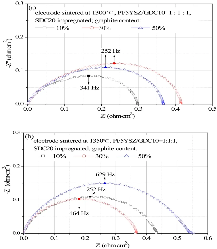
Figure 6 shows impedance spectra of electrodes with SDC20 impregnation, prior to that the electrodes were given varied contents of graphite to create pores within electrodes. In the tests of (a) and (b) the electrodes were heated at 1300 ℃ and 1350 ℃, respectively. The minimum polarization resistance reached 0.3 ohm·cm2on the electrodes with 10wt.% graphite addition and heated at 1300 ℃, while the minimum polarization resistance was 0.36 ohm·cm2on electrodes with 30%graphite addition and heated at 1350 ℃.
3.4 Effects of test temperature
Arrhenius plots of the polarization resistance are given in Figure 7 in the temperature range from 700 to 850 ℃for electrodes with neither graphite addition nor SDC impregnation. The electrodes were heated at 1300 ℃ and the activation energy is 91.3±1.2, 105.0±1.6 and 97.2±1.4 kJ·mol-1for electrode composition (Pt/5YSZ/GDC10) of 1 : 1 : 1, 1:0.5:0.5 and 1 : 0.25 : 0.75,respectively. The electrode of equal ratio had the least activation energy of 91.3±1.2 kJ·mol-1.

Fig.6 Electrochemical impedance spectra of electrodes with addition of graphite as pore former, followed by SDC20 impregnation. (a) electrodes were heated at 1300 ℃ and (b) electrodes were heated at 1350 ℃. The minimum resistance occured at higher graphite content if the electrode was heated at higher temperature

Fig.7 Arrhenius plot of the polarization resistances of electrodes with varied ratio of Pt/5YSZ/GDC10. The electrode of equal ratio(Pt/5YSZ/GDC10=1 : 1 : 1) had the minimum activation energy of 91.3±1.2 kJ·mol-1
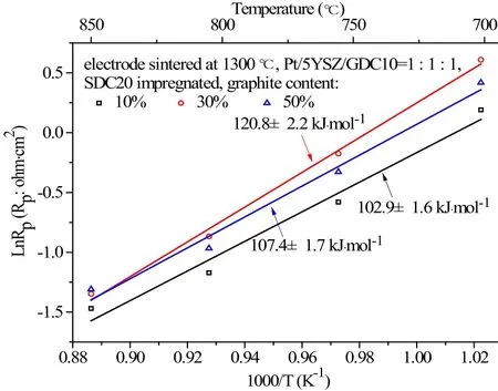
The Arrhenius plot of polarization resistance of the impregnated electrodes at three levels of graphite addition, in the same temperature range of 700-850 ℃are given in Figure 8. The electrodes were fabricated with equal ratio of Pt/5YSZ/GDC10 and the activation energy of these impregnated electrodes with graphite content of 10%, 30% and 50% were 102.9±1.6,120.8±2.2 and 107.4±1.7 kJ·mol-1, respectively. The impregnated electrodes with graphite content of 10%was least sensitive to temperature variation.
3.5 Effects of co- firing

Fig.8 Arrhenius plot of polarization resistance of the impregnated electrodes at three levels of graphite addition, in the temperatures range of 700 ℃-850 ℃. The electrodes had equal ratio of Pt/5YSZ/GDC10. Impregnated electrodes with 10 wt.% addition of graphite had the least activation energy of 102.9±1.6 kJ·mol-1

Fig.9 Impedance spectra of electrodes co- fired with electrolyte at two temperatures: (a) 805 ℃ and (b) 855 ℃, respectively. The electrodes had equal ratio of Pt/5YSZ/GDC10 and were given 10 wt.% graphite, followed by SDC20 impregnation. Electrodes co- firing at 1350 ℃ had lower polarization resistanc
The impedance spectra of electrodes co-fired with green electrolyte tape are shown in Figure 9 for two temperatures: (a) 805 ℃ and (b) 855 ℃. The electrodes were first given 10wt.% graphite before SDC20 impregnation. At 805 ℃, the electrodes cofired at 1350 ℃ had less resistance of 0.47 ohm·cm2,lower temperature co-firing at 1300 ℃ caused larger electrode resistance of 0.6 ohm·cm2. At 855 ℃,electrodes co-firing at 1350 ℃ had less resistance of 0.32 ohm·cm2, lower temperature co-firing at 1300 ℃resulted in higher electrode resistance of 0.35 ohm·cm2.
4 Discussion
The key of building an active solid oxide electrode is to expand and maintain the triple phase boundary(TPB) where gaseous phase, ionic and electronic passages jointly meets. As the ionic passage is finally connected to the electrolyte and the ionic transport is not as fast as electrons, most of effective TPB in fact locates around the electrolyte. The contact between TPB and electrolyte is therefore important to electrode performance. In the tests shown in Figure 3,at three electrode heat temperatures, i.e. 1250, 1300 and 1350 ℃, the three-component electrode made of equal ratio of Pt/5YSZ/GDC10 consistently gives the least polarization resistance. In these electrodes,5YSZ is expected to enhance contacts between electrode and YSZ-based electrolyte. There should be a balance in realizing both effective TPB length and good electrode/electrolyte contact. For example,higher heating temperature improves electrode/electrolyte contact but decreases TPB length due to particle growth/coarsening. In the test of Figure 3(d),resistance of all electrode are almost equal, meaning that TPB loss is dominant if the electrodes are overheated, say, at 1400 ℃. In case of co-firing of the electrode with electrolyte, a good contact between electrode/electrolyte can only be obtained provided the electrolyte is well densified, which on the other hand can be indicated by the less pinholes within the electrolyte cross-section (see Figure 1(a) vs. (b)). In the co- firing tests shown by Figure 9, lower electrode resistance is realized at higher co- firing temperature of 1350 ℃, noting that the lower resistance is obtained at 1300 ℃ if the electrode and electrolyte are heated separately, e.g. the electrolyte is pre-sintered at 1500 ℃first, then the electrode at 1300 ℃ (see Figure 3(b) vs.Figure 8). At a same heating temperature, the co- firing electrode has slightly higher resistance compared to the separately-heated counterpart. Heated at 1350 ℃,with SDC20 impregnation and 10% graphite addition,the resistance of the separately heated electrode is ca. 0.43 ohm·cm2(see Figure 5(b)) and it is ca.0.47 ohm·cm2(see Figure 9(a)) on the co-firing electrode.
Doped ceria such as GDC is widely used as electrode/buffer-layer material[24,25,56-61], but its sintering features normally does not match that of YSZ, e.g., GDC starts to sinter at higher temperature and the shrinkage rate is lower[62-64]. Besides, the thermal expansion of GDC is moderately higher than that of YSZ, e.g. the expansion coefficients of YSZ and GDC are 10×10-6and 12×10-6K-1, respectively[65,66]. Therefore the good contact between electrode/electrolyte must be carefully designed and realized if a GDC-containing electrode is to be prepared and used on an YSZ-based electrolyte. In the test of Figure 4, the lowest resistance of 0.9 ohm·cm2is obtained on the two component Pt/GDC10 electrode with Pt content of ca.57% (Pt/GDC10=1 : 0.75), while a comparable, even better, electrode resistance of ca.0.9 (for 1350 ℃) and 0.7 (for 1300 ℃) ohm·cm2can be realized on a three component electrode (Pt/5YSZ/GDC10) with lower Pt content of 33%.
In designing the TPB for a solid electrode, the proportion of ionic, electronic and gaseous passage is important and subject to additional factors. Varying oxide composition and ratio is not a very effective means to substantially reduce electrode resistance.Heated at 1350 ℃, the lowest resistance of Pt/GDC10 (Figure 4(b)), Pt/5YSZ (Figure 4(a)) and Pt/5YSZ/GDC10 (Figure 3(c)) are almost all equal to 0.9 ohm·cm2. On the other hand, addition of graphite can reduce electrode resistance effectively and economically. Heated at 1300 ℃, the resistance of the electrode made of equal ratio Pt/5YSZ/GDC10 was reduced from 0.70 to 0.43 ohm·cm2by adding 30%graphite (see Figure 3(b) vs. Figure 5). Note that via the addition of graphite, the Pt load of electrode is also decreased from 33% to 23%.
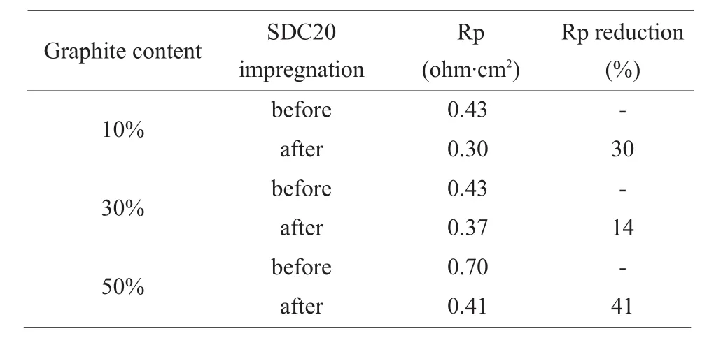
The effects of electrode impregnation depends on electrode porosity. The optimal graphite content varies, i.e. it is 10% if the electrode will be heated at 1300 ℃, 30% if the electrode is to be heated at 1350 ℃(see Figure 6). SDC20 impregnation seems to favor lower graphite addition and higher electrode heating temperature requires more graphite content. As an effective means to improve electrode performance,SDC20 impregnation reduces electrode resistance remarkably. Table 1 lists resistance of electrodes before and after SDC20 impregnation, SDC20 impregnation is able to reduce electrode resistance by up to 41%. SDC20 impregnated electrodes in general is more sensitive to temperature change. For example,the activation energy of the electrodes without impregnation lies in the range of 90-100 kJ·mol-1,while it is 100-120 kJ·mol-1for the impregnated electrodes (see Figure 7 and 8). As reaction kinetics normally is more sensitive to temperature change,SDC20 impregnation possibly facilitates some transport process, making reaction kinetics more prominent in an overall electrode process than the diffusion transport processes do in oxide solids.

Tab.1 Resistance of electrodes before and after SDC20 impregnation. (Pt/5YSZ/GDC10=1 : 1:1, electrode heated at 1300 ℃, tested at 805 ℃ in air)
5 Conclusion
Besides expanding and maintaining the TPB,good contact between electrode and electrolyte is also important to build a solid electrode of activity.In a three-component electrode made of Pt/5YSZ/GDC10 prepared on 5YSZ electrolyte, 5YSZ in the electrode can enhance the contact of electrode/electrolyte, therefore electrode resistance decreases and the optimal ratio of Pt/5YSZ/GDC10 is 1 : 1 : 1.The platinum load can be further reduced by properly introducing graphite while lower electrode resistance is realized. The optimal content of graphite depends on electrode composition and treatment conditions. The optimal graphite content normally lies in the range of 10-30wt.%. SDC20 impregnation improves electrode performance remarkably, and possibly favors less graphite addition. SDC20 impregnated electrodes in general is more sensitive to temperature change. The co- fired electrode together with electrolyte has slightly higher resistance compared to its pre- fired counterpart.
Acknowledgement
The work was done in Zhentai Energy Technology(Z-etech) Co. Ltd. and received financial supports from Innovation Seedling Projects of Zigong City(2017CXM02), Key R&D Program of Sichuan Province (2017GZ0391) and National Key Research and Development Program (2016YFE0102600).
