Fractal Uniform Circular Arrays Based Multi-Orbital-Angular-Momentum-Mode Multiplexing Vortex Radio MIMO
2018-09-06LinjunZhaoHailinZhangWenchiCheng
Linjun Zhao, Hailin Zhang*, Wenchi Cheng
1 State Key Laboratory of Integrated Services Networks (ISN),and School of Telecommunications Engineering,Xidian University, Xi’an 710071, China
2 School of Electrical Engineering, Shaanxi University of Technology, Hanzhong 723000, China
Abstract: A radio wave driven by Orbital angular momentum (OAM) is called a vortex radio and has a helical wavefront. The differential helical wavefronts of several vortex radios are closely related to their topological charges or mode numbers. In physics, two or more radio waves with different mode numbers are orthogonal to their azimuth angles. With the development of radio communication technologies, some researchers have been exploring the OAM-based multi-mode multiplexing(multi-OAM-mode multiplexing) technologies in order to enhance the channel spectrum ef ficiency (SE) of a radio communication system by using the orthogonal properties of vortex radios. After reviewing the reported researches of OAM-based radio communication, we find that some breakthroughs have been made in the combination of OAM and traditional Multi-Input-Multi-Output (MIMO). However, the existing technology is not suf ficient to support OAM-based MIMO system to achieve maximum the channel SE. To maximize the spectrum efficiency of OAM-based MIMO system, we present a reused multi-OAM-mode multiplexing vortex radio (RMMVR) MIMO system, which is based on fractal uniform circular arrays (UCAs). The scheme described in this study can effectively combine multi-OAM-mode multiplexing with MIMO spatial multiplexing. First, we present the generation of RMMVR MIMO signals. Second, under line-of-sight (LOS) propagation conditions, we derive the channels of the RMMVR MIMO system. Third, we separate the RMMVR MIMO signals using an orthogonal separation method based on full azimuth sampling. Finally, we introduce the method for calculating the channel capacity of the RMMVR MIMO system. Theoretical analysis shows that the scheme proposed in this study is feasible.Moreover, the simulation results show that spatial and mode diversity are obtained by exploiting fractal UCAs. However, to enhance the channel SE of RMMVR MIMO system, an interference cancellation method needs to be introduced for zero-mode vortex radios, and some methods of multi-OAM-mode beams convergence and mode power optimization strategy should be introduced in the future.
Keywords: vortex radio; reused multi-OAM-mode multiplexed vortex radio (RMMVR)MIMO; fractal uniform circular arrays(UCAs);signal orthogonal separation.
I. INTRODUCTION
In this study, channel models of an RMMVR MIMO system are constructed based on fractal UCAs.
According to Maxwell theory, electromagnetic radiation involves both linear momentum and orbital angular momentum (OAM), and the electromagnetic wave driven by OAM is called a vortex electromagnetic wave, whose wavefront is helical [1], [2]. Mathematically, the expression of a vortex electromagnetic wave signal involves a phase factor exp(jℓϕ),where j is plural, ℓ is the topological charge or mode number, and ϕ is the azimuth [3],[4]. When the modes of ℓ1and ℓ2differ, the phase factors exp(jℓ1ϕ) and exp(jℓ2ϕ) are mutually orthogonal to the azimuth angles.Similar to the code division multiplexing and frequency division multiplexing [5], several different OAM-modes electromagnetic waves can share the same radio frequency (RF) channels [4], [6], [7]. The amplitudes, phases and modes of the multi-OAM-mode multiplexing vortex carrying orthogonal information may further enhance the capacity of a wireless communication system. OAM-based vorticose electromagnetic waves were explored at radio frequency began in 2011 [4]. Since then, the explorations of the OAM-based vortex radio communication have been made progress. In 2014, a group of researchers described an implementation of a communication link over 8 millimeter-wave channels based on OAM to achieve an aggregate bandwidth of 32 Gbit/s over a distance of 2.5 meters was reported [8].
In November 2012, there were reports of disagreement about the basic theoretical concept of OAM multiplexing at radio frequencies between the research groups of Tamburini and Thide, and many different camps of communications engineers and physicists, with some declaring their belief that OAM multiplexing was just an implementation of MIMO, and others holding to their assertion that OAM multiplexing is a distinct, experimentally con firmed phenomenon [4], [9]. Another study examined the channel capacity of a vorticose wave communication system based on uniform circular arrays (UCAs) [10]. The channel capacity of the UCA-based vorticose electromagnetic wave communication system was determined to be equal to the number of its elements when parallel alignment1Parallel alignment means that the receiving plane is parallel to the transmitting plane,and the centers of the two planes are coaxial.was used but was very limited when parallel non-aligned2Parallel non-aligned means that the receiving plane is parallel to the transmitting plane,but the centers of the two planes are not coaxial.was adopted.However, the study did not investigate whether the channel of multi-OAM-mode multiplexing vorticose electromagnetic waves generated by UCAs is consistent. In [11], [12], the capacity of a multi-OAM-mode multiplexing vortex radio MIMO system with a helical phase plate antenna was explored. Because the helical phase plate antenna cannot radiate multi-OAM-mode vortex electromagnetic waves simultaneously, reused multi-OAM-mode multiplexing gain was not considered. In 2016, a new con figuration of OAM-MIMO radio communication system, which traveling-wave OAM antennas used independent UCAs as the elements of the transmitting uniform linear array (ULA), was proposed [13]. To facilitate the separation of multimodal vortex radio MIMO signals, each UCA on the ULA sends only an independent modal signal, and every OAM antenna on ULA is able to generate any one desired OAM state, which belongs to a given eigen-mode set.In [3], [14], and [15], methods for generating multi-OAM-mode vorticose electromagnetic signals through UCAs were discussed, but these studies did not indicate how to simultaneously excite multi-OAM-mode multiplexing of a vortex radio. In [16], although the fast Fourier transform (FFT) was used to estimate the topological charge through omnidirectional full azimuthal sampling, authors did not indicate whether the FFT algorithm can be used to separate RMMVR MIMO signals. In 2017, a group of the researchers proposed an OAM-MIMO multiplexing system, and revealed that the propagation distance of vorticose electromagnetic wave had a great in fluence on the gain of OAM-MIMO system [17]. Although this result agreed well with predictions about severely limited distances made by Edfors et al [18],it did not in detail discussed that the different geometrical dimensions of the transceiver antennas can restrain the capacity of the independent mode vortex electromagnetic wave chan-nels, nor does it deal with the signal separation in homologous mode propagation. That same year, some researchers of our team introduced the scheme of OAM-embedded-MIMO system[19]. Based on multi-OAM-mode multiplexing,the authors proposed a novel scheme of mode frequency hopping in [20] and discussed the mode division multiple access in wireless networks in [21].
To maximize the spectrum efficiency of OAM-MIMO system, and to possibly inherit some classical signal processing techniques form traditional MIMO systems in the future,such as network coding [22], QAM modulations/demodulations [23], [24], and full duplex access [25], the available capabilities of OAM-MIMO antennas should be fully utilized.So, we propose a reused multi-OAM-mode multiplexing vortex radio (RMMVR) MIMO system based on fractal UCAs by referring to fractal geometry and array antenna theories[26]. And we discuss how to generate RMMVR MIMO signals. Furthermore, the channels of the RMMVR MIMO system are comprehensively analyzed under line-of-sight (LOS) propagation conditions. The analysis shows that the channels of the RMMVR MIMO system are of two types: parallel-aligned and parallel-nonaligned channels. Notably, under LOS and far-field propagation conditions, the sampling signals of each received element in the fractal UCAs have two parts. The first part pertains to full azimuth uniform sampling signals from the parallel-aligned UCA, and the second part pertains to fixed-azimuth and fixed-distance reception from the parallel-nonaligned UCA.In addition, the orthogonal separation method of RMMVR MIMO signals is discussed. The simulation results show that spatial and mode diversity can be obtained by exploiting fractal UCAs and orthogonal separation in the RMMVR MIMO system.The significance of our works is as follows. (1) the antenna of RMMVR MIMO system can be used effectively.(2) the main factors affecting the capacity of RMMR-MIMO system are revealed and the possible effective methods of capacity enhancement are indicated.
The remainder of this paper is organized as follows. Section II describes the structure of the RMMVR MIMO system. Section III presents the generation of RMMVR MIMO signals. Section IV introduces the channel models of the RMMVR MIMO system. Section V presents the development of the orthogonal separation method for the RMMVR MIMO signals. Section VI introduces the ergodic capacity of the RMMVR MIMO system. Section VII provides numerical evaluations, and Section VIII presents the conclusions.
II. STRUCTURE OF THE RMMVR MIMO SYSTEM
We propose the UCAs-based RMMVR MIMO system, the structure of which is shown in figure 1. The radius of transmission antenna ucatx,n(n =1,2,…,N ) is u, and the number of elements is K. ucatx,1, ucatx,2, ..., ucatx,Nare evenly distributed over the circumference of transmitting array UCATX. The center of UCATXis OTX, and the radius is U. The radius of receiving antenna ucarx,m(m =1,2,…,M ) is r, and the number of elements is K. ucarx,1, ucarx,2, ..., ucarx,Mare evenly distributed over the circumference of receiving array UCARX. The center of UCARXis ORX, and the radius is R. All transmitting elements are on the same plane and have the same electromagnetic characteristics, as do all the receiving elements.Planes UCATXand UCARXare parallel and aligned with each other, and the distance between them is χ. According to [3], [27], the sub-channels from ucatx,n(n =1,2,…,N ) to ucarx,m(m =1,2,…,M ) constitute the RMMVR MIMO system channel. As shown in figure 2, each sub-channel can be shared by K vortex electromagnetic signal modes. Can each sub-channel transmit the same mode set of vortex radio in the MIMO system? Can the receiver use the same structure and same size of fractal UCAs to receive the RMMVR MIMO signals? This study provides three answers to these questions, as follows: (1) generation of RMMVR MIMO signals using fractal UCAs,(2) channel models of the RMMVR MIMO system, and (3) separation of RMMVR MIMO signals through full azimuth sampling.

Fig. 1. Structure of the RMMVR MIMO system based on fractal UCAs.
III. GENERATION OF RMMVR MIMO SIGNALS
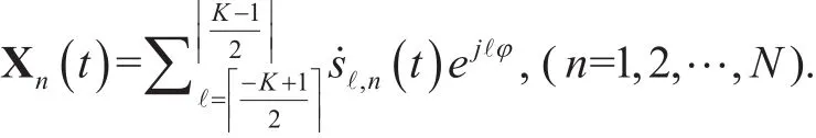
According to [14]–[16], [27]–[31], ucatx,n(n =1,2,…,N ) with K elements can simultaneously excite K vortex electromagnetic wave modes. If these modes carry independent modulation symbols, then K different symbols can be transmitted simultaneously. Vector Sn(t)in Eq. (1) contains the symbols of transmitting antenna ucatx,n(n =1,2,…,N ).

where sℓ,n(t ) is the complex signal carried byℓ vortex electromagnetic wave mode generated by ucatx,nandanddenote the next rounding operator and the rounding operator,respectively.
The send matrix of the RMMVR MIMO system is S(t), which is an N×K block diagonal matrix, as shown in Eq. (2).

where diag[·] denotes the diagonal matrix operator.
According to the generation of multi-OAM-mode vortex electromagnetic waves by UCA[3], [14]–[16], Sn(t) in S(t) must append a linear phase shift associated with the mode of the vortex electromagnetic waves, which forms the phase shift matrix φ(ℓ,ν) as in (3).

Thus, the excitation of each element of transmitting antenna ucatx,n(n =1,2,…,N ) that can produce K vortex electromagnetic wave modes is determined by Eq. (4).

Excitation matrix X(t,ν) is then determined by Eq. (5).
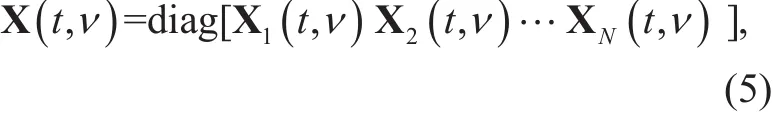
where X(t,ν) is an N × N block diagonal vortex radio signal matrix.
According to [3], driven by X(t,ν),ucatx,1, ucatx,2,…, ucatx,Nproduce K vortex signal modes to form signal matrix X(t), as shown in Eq. (6).

where X(t) denotes an N×1 matrix,[·]′ denotes a transpose operator, and
IV. CHANNEL MODELS OF THE RMMVR MIMO SYSTEM
When the band of the signals is narrow, the geometry of the antenna element (relative to the free space propagation distance) is suf ficiently small, and the main lobes of the receiving and transmitting elements are aligned, the channel attenuation of the transmitting and receiving elements in far- field conditions is determined by Eq. (7) [11].
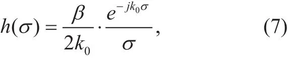
where β is a constant related to the element’s impedance, the permeability of the electromagnetic wave propagation space, and the radiation patterns of the transmitting and receiving antennas;is the wave number; and λ is the carrier wavelength.
For the RMMVR MIMO system shown in figure 2, we let the transmitting element on the sending plane UCATXradiate along the Z axis. When χ≫U and χ≫ R, the channels of the RMMVR MIMO system may be classified into two types of channels:parallel-aligned propagation channels (the channel between ucatx,n0and ucarx,m0) and parallel-nonaligned propagation channels (the channel betweenand ucarx,m0).
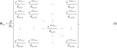
Under narrow-band and far-field propagation conditions, the channels of the transmitting element et,n,ν(ν=1,2,…,K) of the transmitting antenna ucarx,m(m =1,2,…,M ) to the receiving element er,m,k(k =1,2,…,K ) of the receiving antenna ucarx,m(m =1,2,…,M )correspond to the large-scale static fading condition of plane electromagnetic waves. The channel models based on the transceiving elements are shown in Eq. (8),
where Hmndenotes a K × K matrix and dmn,kνdenotes the distance from the element et,n,ν(ν=1,2,…,K) of ucatx,n(n =1,2,…,N ) to the element er,m,k(k =1,2,…,K ) of ucarx,m(m =1,2,…,M ).
Thus, the channel models of the RMMVR MIMO system shown in figure 2 are determined by Eq. (9).
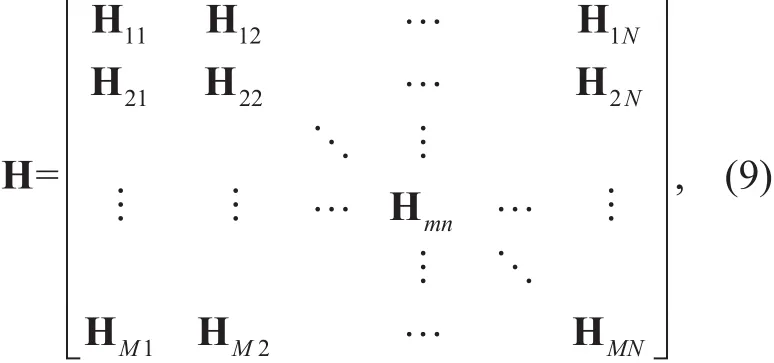
where H denotes an M×N matrix. For the described RMMVR MIMO system, using the channel models in Eq. (9) is inconvenient.
4.1 Parallel-aligned channel models
The channel formed by transmitting antenna ucatx,n0and receiving antenna ucarx,m0can be studied as a parallel-aligned channel.Under far-field propagation conditions, the response of the receiving element er,m0,k(k =1,2,…,K ) of the receiving antenna ucarx,m0(m =1,2,…,M ) is the sum of the narrow-band signals generated by all the elements of the transmitting antenna [32], as shown in Eq. (10).
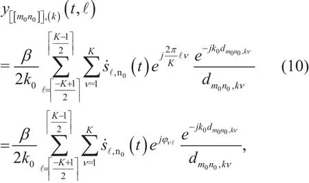
According to [11], [33], we can obtain
where ϕn0,νdenotes the azimuth of the element. Similarly, ϕmk0,is the azimuth of the elementUnder far-field conditions, when χ≫u and χ≫r,h old s. The amplitude partofis equal to. If the approximation equationis applied to the phase partof, then
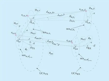
Fig. 2. Reception of RMMVR MIMO signals at χ.

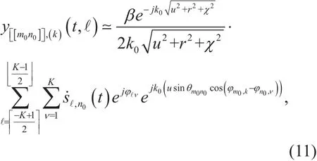
According to the geometric relationship shown in figure 2,Eq. (10) can then be calculated using Eq. (11).
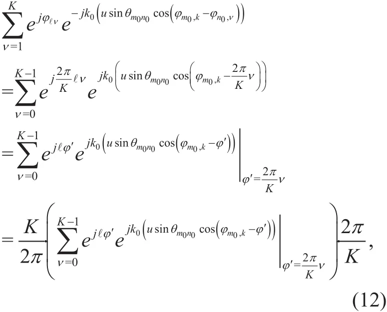
According to [32], [34], the response of receiving element er,m0,k(k =1,2,…,K) can be approximated by K→∞. Therefore, the moment K→∞ in Eq. (12) expresses′. Eq.(12) can be simplified as Eq. (13).

According to the Jacobi-Anger expans i o n [3 5],and the Bessel function of the first kind is. Thus, Eq.(13) can be further reduced as Eq. (14).

By substituting Eq. (14) into Eq. (11),can be approximated as Eq.(15).

When receiving element er,m0,k(k=1,2,...,K)continues to move on the circumference of receiving antenna ucarx,m0, ϕm0,kin Eq. (16) will continuously change in the interval [0,2π].We let ϕm0,k=ϕ (ϕ∈[02π]) and substituteinto Eq. (15). Hence,Eq. (15) can be expressed as Eq. (16).

All the vortex radio signal modes generated by transmitting antenna ucatx,n0are given in Eq. (17).
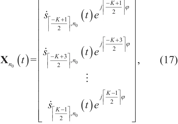
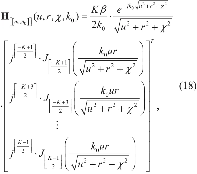
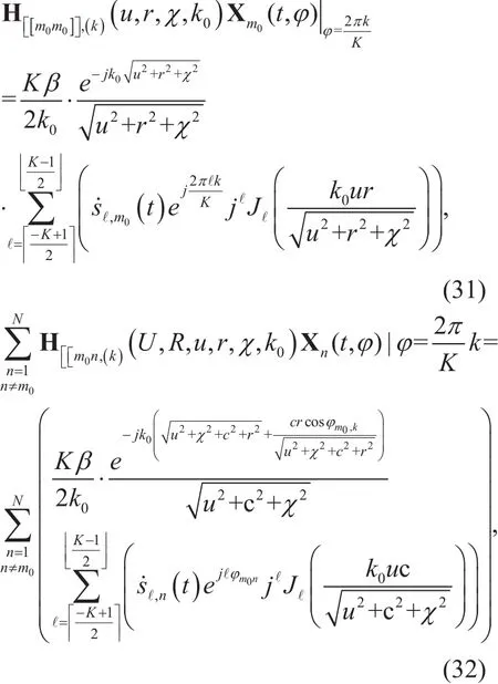
According to Eq. (18), the fading is related to the modes of the vortex signals generated by UCAs in the parallel-aligned propagation condition. The fading of a single-mode vortex wave is the product of the large-scale flat fading with the Bessel fading term. The kind of Bessel function is equal to the mode of the vortex wave, whose parameters are related to the radii of u and r, propagation distance χ,and wave number k0, as shown in Fig 2.
4.2 Parallel-nonaligned channel models
ucarx,m0andconstitute a parallel-nonaligned channel for investigating all the parallel-nonaligned channel characteristics in figure 2.
The geometric projection method is employed to analyze this problem, as shown in figure 3. Parallel-nonaligned channels can be converted into parallel-aligned channels for study. The specific projection relationship is as follows: the orthogonal projection of transmitting antennaon receiving plane UCARXis, that is, pointis both the center ofand the projection point of point Ot,non receiving plane UCARX. According to the geometric projection relationship, receiving element er,m0,k(k =1,2,…,K ) of receiving antenna ucarx,m0can be regarded as a receiving element on the virtual receiving antennathe center and radius of which areand d, respectively. The parallel-nonaligned propagation is converted into parallel-aligned transmission.
The coordinate relationship in the system is shown in figure 3, in whichis a cylindrical coordinate system. The geometric relationship between receiving antennaand transmitting antennais evaluated. The distance dm0n,kνbetween receiving element er,m0,k(k=1,2,…,K) and the center Ot,nof transmitting antennasatisfieswhere the azimuth angle of transmitting element et,n,νis, and the azimuth angle of receiving element er,m0,k[5,16]. The signal received by receiving element er,m0,k(k=1,2,…,K) can be determined using Eq. (19).

Fig. 3. Reception of RMMVR MIMO signals in the parallel-nonaligned condition at χ.
By referring to Eq. (15), Eq. (19) can be simplified as Eq. (20).
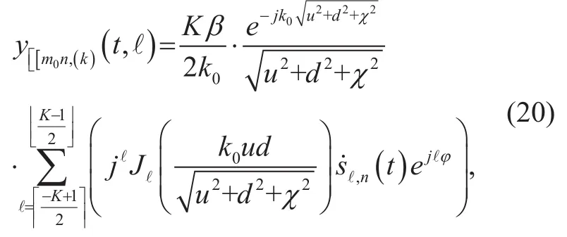
When receiving element er,m0,k(k=1,2,...,K)moves on the circumference of ucarx,m0,the radius d of the virtual receiving antenna uc~arx,m0varies with the receiving azimuth angle ϕ, as shown in figure 4.From the geometric relationship shown in figure 3, we find that Δφmn=φm−φnand. According to the geometric relationship shown in figure 4,d2= c2+r2+2cr cosϕm0,k.
a) To determine d: Under far- field conditions,when R≫r, U≫u, χ≫u, and χ≫r,if c≫r, then. The amplitude portion d of Eq. (20) is approximated as Eq. (21).
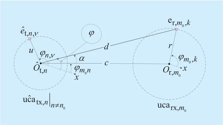
Fig. 4. Mutual relationship between d and φ.

From the relationship shown in figure 3, for the d in the phase part in Eq. (20), we observe thatUnder far-field propagation conditions, Eq.(22) holds.

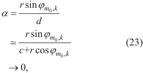
b) To determine ϕ: According to the geometric relationship shown in figure 4, ϕ= ϕm0n+α. We apply the sine theorem to triangularand obtain. If c≫r and sinα⋍α are satis fied, then
When receiving element er,m0,k(k=1,2,...,K)traverses the circumference of ucarx,m0,0≤ ϕm0,k≤2π. ϕ in Eq. (24) approximates a constant.

where ϕm0nis shown in figure 4. Substituting Eqs. (21, 22, 23, 24) into Eq. (20) yields Eq.(25).

Eq. (25) indicates the following:
1) In the RMMVR MIMO system shown in figure 2, the vortex signals transmitted by receiving element er,m0,k(k =1,2,…,K ) on parallel-nonaligned transmitting antennahave a fixed receiving azimuth angle ϕm0nunder certain conditions.
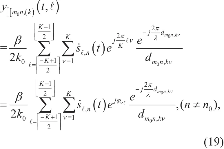
The signals Xn(t) are shown in Eq. (26)fromto determine the parallel-nonaligned multi-OAM-mode vortex signal channel function, as shown in Eq. (27).
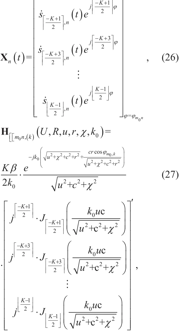
Eq. (27) indicates that the fading of the parallel-nonaligned multi-OAM-mode signals generated by UCAs in the RMMVR MIMO system have Bessel function components.The fading of a single-mode vortex wave is a product of the large-scale fading by the Bessel fading term; the order of the Bessel function of the first kind is equal to the mode of the vortex wave whose parameters are related to the radii of u and r, propagation distance χ,and wave number k0.
4.3 Channel models of RMMVR MIMO
We let the system shown in figure 2 be an N×N MIMO system. The radii of antennas ucatx,n(n =1,2,…,N ) and ucarx,m(m =1,2,…,M ) are u and r, respectively.Under large-scale fading and parallel-aligned propagation conditions, the RMMVR MIMO signals received by ucarx,m, (m =1,2,…,M )are determined by Eq. (28).
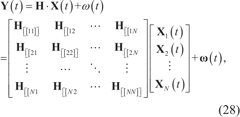
where Y(t) =[Y1( t) Y2(t) … YN(t )]′ is the signal vector, the additive complex white Gaussian noise isand each power of which is δℓ,n,
The received signal of element er,m0,k(k =1,2,…,K ) on receiving antenna ucarx,m0is shown in Eq. (29).
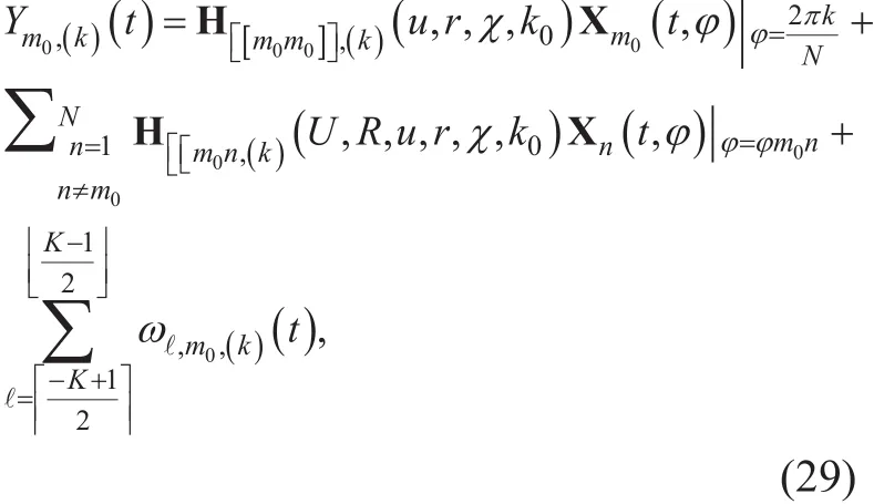
where Ym0,(k)(t ) denotes the response of the k-element of ucarx,m0. Evidently, Ym0,(k)(t) has three parts, including the parallel-aligned and parallel-nonaligned components.
V. SEPARATION OF RMMVR MIMO SIGNALS
According to the channel characteristics of the RMMVR MIMO system described in Section(IV), the K-discrete mode spectrum can be obtained using the FFT algorithm of variable modefor signals Ym(t) ucarx,m(m =1,2,…,M ) [36],[37]. With receiving antenna ucarx,m0as an example, the receiving signals of all its elements are represented as Eq. (30).
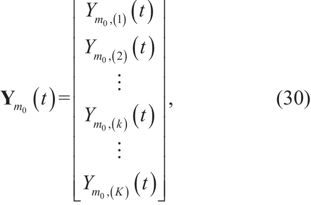
where Ym0,(k)(t ) denotes the response of the k-element of ucarx,m0, as shown in Eq. (29).Ym0,(k)(t ) is composed of two parts: parallel-aligned components and parallel-nonaligned components, which are shown in Eqs.(31) and (32), respectively.
Here, we assume that the mode information of the OAM is not distorted in the propagation of free space. According to [36], [37],the K-point FFT algorithm about mode ℓis employed for

A p p l y i n g FFT(f1(k )+ f2(k ))=FFT (f1(k ))+ FFT ( f2(k )) results in Eqs.(33) and (34).


If χ≫r, χ≫R and χ≫U, then χ2+c2≫cr. Thus,and therefore, Eq. (35) holds. Meanwhile,
Eqs. (33) and (35) produce Ym0(t), as shown in Eq. (36).
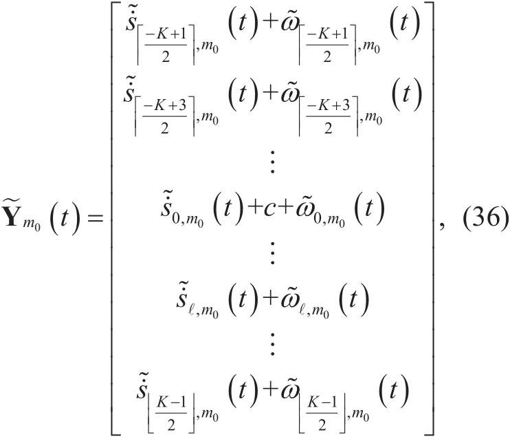
where

VI. ERGODIC CAPACITY ANALYSIS

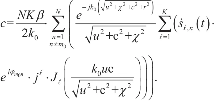
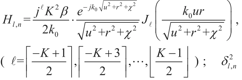
For the N×N RMMVR MIMO system, at LOS with Rician factor ρ, the channels can be divided into N parallel SISO channels, one of which simultaneously transfers K vortex magnetic wave modes. Because the different modes can be separated by Eq. (34), the normalized ergodic capacities of the RMMVR MIMO system can be estimated using Eq. (37)[7], [38].
As shown in Eq. (37), E(·) denotes the expected value; Pl,ndenotes the power of the signal carried by the ℓ mode vortex wave of transmitting antenna ucatx,n, (n =1,2,…,N ); Hl,nrepresents a large-scale slow fading of ucatx,nto ucarx,n;
VII. NUMERICAL EVALUATIONS
In this section, we perform numerical analyses to determine the ergodic capacity of the proposed RMMVR MIMO scheme. We employ the Monte Carlo method to evaluate the ergodic capacity of the system. The numerical analysis program for the ergodic capacity loops 3000 times.
7.1 Simulation parameters
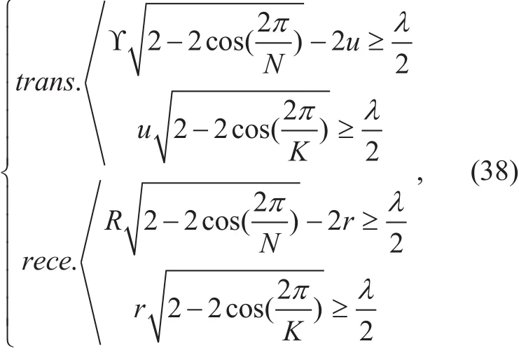
When the sizes of the transmitting and receiving antennas as in Figure 1 satisfy Eq. (38), the coupling components between the elements on the receiving or transmitting plane can be ignored [34]. The simulation parameters used in this study are listed in table 1, and for feasibility, we set λ=0.125 and, and thepower assigned to each vortex magnetic wave mode is equal, that is,

Table I. Simulation parameters.
7.2 N=1
With these con figurations, the communication system degenerates into a parallel-aligned single-input-single-output (SISO) system, which generates eight vortex magnetic wave modes simultaneously.
Figure 5 depicts the variations in the ergodic capacities of modevortex electromagnetic waves with receiving antenna radius r or transmitting antenna radius u. We set the parameters as follows: ρ=1,α=11d B, χ=10λ, and r=λ. As shown in figure 5, radius u increases from 1λ to 9λ. The ergodic capacities of the eight vortex magnetic wave modes cannot be maximum or minimum at the same time because each channel has its own unique type of Bessel function of the first kind. Moreover, when u is located in the interval [2λ,6λ], the sum of the ergodic capacities of the eight vortex electromagnetic wave modes remains almost constant at approximately 5.3444bps/ Hz . When we set the parameters as ρ=1, α=11d B, χ=10λ, and u=λ, the effect of r on the system capacity is similar to that of u.
Figure 6 plots the variations in the ergodic capacities of modevortex electromagnetic waves with Rician factor ρ.We set the parameters as follows: α=11d B,u=λ, r=λ, and χ=10λ. Clearly, each ergodic capacity of the eight vortex magnetic wave modes is invariable. Meanwhile, the corresponding channel capacity of the mode ℓ=0 vortex magnetic wave is approximately twice the channel capacity of modes=1, and the corresponding channel capacity of modes=1 is approximately nine times the channel capacity of modes=3. As shown in figure 6, the corresponding channel capacities of modes=2,=3, and=4 are approximately 2.2602bps/ Hz, 2.7446× 10⁻⁴bps/ Hz,and 1.6669× 10⁻⁶bps/ Hz, respectively.
Figure 7 illustrates the variations in the ergodic capacities of vortex electromagnetic wave modeswith the power α(dB). We set the main parameters set as follows: ρ=0.5, χ=10λ, u=λ, and r=λ.Clearly, each ergodic capacity of the eight vortex magnetic wave modes increases as the power α(dB) increases, but the corresponding channel capacity of the low mode increases faster than that of the high mode.
7.3 N=4
In Eq. (35), when c=0, the capacity of the RMMVR MIMO system is at the upper limit because all modes of vortex electromagnetic waves can carry information; when c≠0 and no information can be modulated to the zero-mode vortex electromagnetic wave, the capacity of the RMMVR MIMO system is at the lower limit. Thus, the results described below are based on c=0 and c≠0. The power strategy for each mode signal is similar to that in Section VII-B.
Figure 8 shows the variations in the ergodic capacities of an eight-mode vortex electromagnetic wave RMMVR MIMO system with radius U, Rician factor ρ, and signalto-noise ratio α. We set the main parameters as follows: R=10λ, u=λ, r=λ, and χ=10λ.Clearly, given α and ρ, the ergodic capacity of the RMMVR MIMO system is independent of radius U (or R). Moreover, given constant α, the greater ρ is, the greater the ergodic capacity of the RMMVR MIMO system is.In addition, irrespective of whether the zero-mode vortex electromagnetic wave carries information, the capacity of the RMMVR MIMO system varies greatly with increasing α. This result is because the attenuation of the Bessel function of the first kind of zero order is lower than the decay of their higher order functions, as shown in figure 7. The effect of R on system capacity is similar to that of U.

Fig. 5. Ergodic capacities versus u (λ) ( or r (λ)).

Fig. 6. Ergodic capacities versus Rician factor ρ.
Figure 9 illustrates the variations in the ergodic capacities of the eight-mode RMMVR MIMO system with radius u. As shown in figure 9, with increasing u, the ergodic ca-pacity of the RMMVR MIMO system initially increases and then decreases, and this performance becomes increasingly clear as ρ and α increase. In comparison with Figs. 9(a) and 9(b), the capacity increase in the corresponding nonzero-mode channel is considerably larger than the capacity decrease of the zero-mode channel with increasing u, which is consistent with the conclusion shown in figure 7. The effect of r on the system capacity is also similar to that of u.
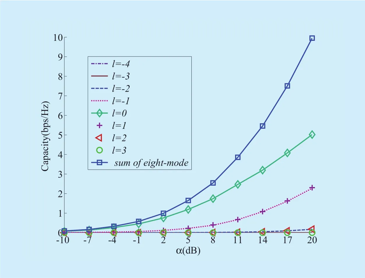
Fig. 7. Ergodic capacities versus power α.
Figure 10 shows the variations in the ergodic capacities of the eight-mode RMMVR MIMO system with propagation χ. We set U=10λ, R=10λ, r=λ, and u=λ. Apparently, with increasing χ, the channel ergodic capacity of the constructed MIMO system is attenuated by an approximate exponent. For example, given ρ=0.5 and α= −10dB, when χ takes 10λ, 20λ, and 30λ, the ergodic capacities of the system are 0.3437bps/ Hz,0.0915bps/ Hz, and 0.0406bps/ Hz, respectively; given ρ=0.5 and α=11dB, when χ takes 10λ, 20λ, and 30λ, the ergodic capacities are 0.3437bps/ Hz, 0.0915bps/ Hz, and 0.0406bps/ Hz, respectively.
VIII. CONCLUSIONS
In this study, channel models of an RMMVR MIMO system are constructed based on fractal UCAs. An RMMVR MIMO signal separation method is developed using the FFT algorithm.We simulate the ergodic capacities of a 1× 1
RMMVR MIMO (or SISO) system and a 4× 4 RMMVR MIMO system. According to the analysis results, we conclude the following:
1) Under the condition of channel determination, the ergodic capacity of the low-mode vortex electromagnetic wave is larger than that of the high-mode vortex electromagnetic wave.
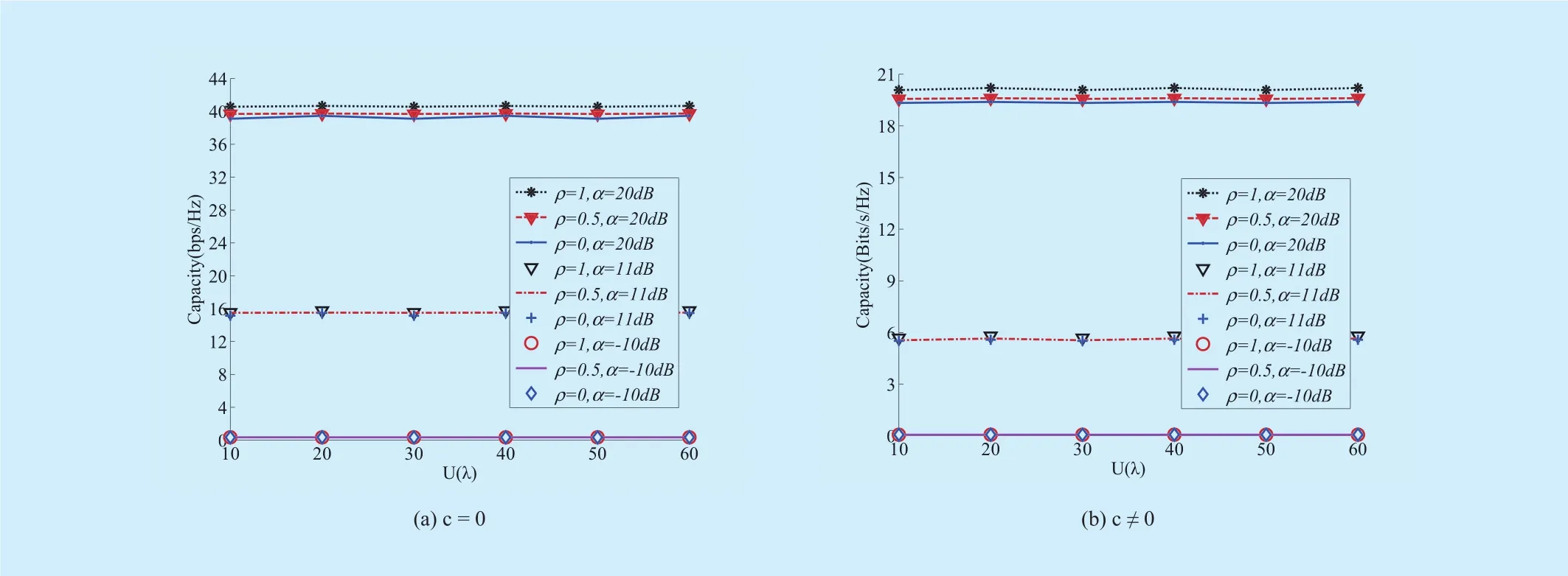
Fig. 8. Ergodic capacities of the RMMVR MIMO system versus the radius U(λ).

Fig. 9. Ergodic capacities of the RMMVR MIMO system versus u (λ).
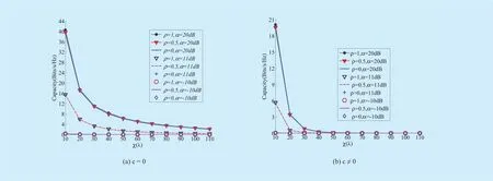
Fig. 10. Ergodic capacities of the RMMVR MIMO system versus χ (λ).
2) For a multi-OAM-mode vortex electromagnetic wave communication system based on fractal UCAs, a mode power optimization strategy and a multi-OAM-mode beam convergence method need to be introduced to obtain enhanced system performance.
3) The channel of a conventional N×N MIMO system can be converted into parallel N SISOs.
4) For a nested multi-OAM-mode vortex magnetic wave MIMO system based on fractal UCAs, interference suppression techniques must be introduced to the zero-mode vortex electromagnetic wave.
In addition, an effective RMMVR MIMO signal separation under the condition of multi-OAM-mode information distortion is also one of our future works. This work is supported by the National Natural Science Foundation of China (No. 61671347).
杂志排行
China Communications的其它文章
- DNN-Based Speech Enhancement Using Soft Audible Noise Masking for Wind Noise Reduction
- Delay-Based Cross-Layer QoS Scheme for Video Streaming in Wireless Ad Hoc Networks
- An MAC Layer Aware Pseudonym (MAP) Scheme for the Software De fined Internet of Vehicles
- Asymptotic Analysis for Low-Resolution Massive MIMO Systems with MMSE Receiver
- Golay Pair Aided Timing Synchronization Algorithm for Distributed MIMO-OFDM System
- Joint Non-Orthogonal Multiple Access (NOMA) &Walsh-Hadamard Transform: Enhancing the Receiver Performance