Outage Probability Minimization for Low-Altitude UAV-Enabled Full-Duplex Mobile Relaying Systems
2018-06-07MengHuaYiWangZhengmingZhangChunguoLiYongmingHuangLuxiYang
Meng Hua, Yi Wang, Zhengming Zhang, Chunguo Li, Yongming Huang, Luxi Yang,*
1 School of Information Science and Engineering, Southeast University, Nanjing 210096, China
2 National Digital Switching System Engineering and Technological Research Center, Zhengzhou 450002, China
3 School of Electronics and Communication Engineering, Zhengzhou University of Aeronautics, Zhengzhou 450046, China
I. INTRODUCTION
In wireless cooperative communication systems, the relay-assisted communication is an effective technique for improving transmission reliability as well as power efficiency [1]-[9].However, in conventional relaying systems,which operate in the half-duplex mode: either frequency-division duplex (FDD) or time-division duplex (TDD), is inefficiency. Recently,a large amount of literature have investigated the full-duplex protocol for the sake of operating in time and frequency simultaneous, which boost the system capacity twice theoretically[10]-[14].
In order to improve cooperative communication system throughput or decrease system outage probability, one simple method is to increase the source/relay transmit power, whereas such scheme is subject to lower-powered source/relay node. The second method is to optimize the relay location as well as source/relay transmit power allocation. This method is effective as the propagation loss of radio frequency signal over source-relay distance and relay-destination distance have significantly impacted on the link reliability of the relaying system. For half-duplex protocol, optimal power allocation and relay location have been extensively studied (refer to [15]-[17]) and the references therein). For full-duplex protocol,in [18], the author investigated relay-enabled full-duplex decode-and-forward relaying system and the optimal location are achieved by minimizing the system outage probability. In[12], the same authors also investigated relaying system for outage probability minimization problem by jointly optimizing source/relay power allocation and static relay location. However, the mentioned above are all considered in static relaying systems, actually,in some specific scenarios, e.g., wild forest,desolate area and mountainous area, it is not wisdom to deploy a large amount of relays to serve the ground nodes due to the difficulty in deploying numerous relays.
Fortunately, the unmanned aerial vehicles(UAVs) provide a promising effective technique to serve the ground nodes in harsh area due to their flexible mobility and low cost.Recently, the demand for UAVs had been increasing in many applications, such as public safety, disaster management, surveillance and communication [19]-[25]. Instead of focusing on design spectrum efficiency or energy efficiency [26], [27], here we pay attention to optimize outage in time-intolerant situation. Compared with traditional static relay,the prominent advantage over UAV is that it provides new opportunities to enhance system network reliable performance by dynamically adjust their locations [28]-[30]. In [28], the authors optimized the deployment of UAVs to service users for minimizing the total UAV transmit power while satisfying the users’ rate requirements in a downlink scenario. In[29],the same authors considered data collection problem with an UAV to gather data from internet of things (IoT) devices, and the optimal UAV trajectory was obtained while minimizing the total transmit power of IoT devices.In [30], the authors considered a high-altitude UAV as mobile relaying for cooperative communication, and assume the channel are only dominated by line-of-sight (LoS). However, the low-altitude UAV is not considered which may have different channel condition and mathematical analysis, meanwhile the UAV-enabled full duplex DF technique has not been studied.
Inspired by above illustrations, we consider a more general case where the static relay is replaced by UAV for cooperative communication. A novel UAV-enabled full-duplex scheme for the minimizing sum outage probability in relaying system is proposed. Specifically,the UAV flies above within a specific area to service two ground-node over a finite time interval. By exploiting the two important factors: source/relay power allocation and relay trajectory. On the one hand, the source/relay transmit power are constrained by the limited battery capacity, with the variation channels of source-relay and relay-destination induced by UAV movement, the source/relay transmit power should be carefully designed. On the other hand, UAV can experience the best channel conditions when hovering above the source and destination node via exploiting the controllable mobility of UAV. Thus, in this paper, we propose a joint power and trajectory optimization problem to minimize the sum outage probability, which subjects to practical maximum UAV speed and its launching/landing location as well as average power constraints at source and relay.
In this paper, we assume the UAV has the ability to operate in full-duplex DF model for information reception and transmission simultaneously in same frequency, which theoretically gain 2x throughput. The sum outage probability is used as our optimization criteria.The main contributions of this paper are summarized as follows:
· We firstly present a model for a UAV-enabled full-duplex relaying system, in which UAV is utilized to assist communication from source to destination for the sum outage probability minimization over a time interval. The limitations of UAV speed and average transmit power of relay/source are considered, which are the vital factors for system reliable performance.
· Next, for a given mobile relaying trajectory,the optimal transmit power of source and relay are obtained by solving Karush-Kuhn-Tucker (KKT) conditions. It is shown that when UAV moves away from source over each time slot, source needs to transmit more power to improve the signal-to-noise(SNR) of source-relay link. As UAV moves closer to destination, less relay power is needed for transmitting due to the shorter relay-destination link distance.
· Then, for a given source/relay power allocation. We first formulate this trajectory optimization problem as standard quadratically constrained quadratic program (QCQP)problem, and solve it through dual form.Based on above two algorithms, an iterative algorithm is proposed for jointly optimizing source/relay power allocation and relay trajectory alternately.
This paper is organized as follows. Section II introduces the system model and problem formulation. Section III studies joint source/relay power allocation and relay trajectory optimization problem which consists of four subsections. In the first subsection, the optimal source/relay power allocation are obtained with the given relay trajectory. In the second subsection, the optimal relay trajectory is achieved with the fixed source/relay power allocation. In the third subsection, an iterative algorithm is proposed to jointly optimize both source/relay power allocation and relay trajectory alternately. At last subsection, the convergence property and complexity analysis are provided. The numerical results and comparisons are presented in Section IV. Finally,the conclusion is given in Section V.
Notations: Bold uppercase, lowercase letters and italic letters are used to represent matrices, vectors and scalars, respectively. The superscript (.)Tdenote the transpose operator.We userepresents the biggest integer that no bigger than a, anddenotes the smallest integer that is no small than a.In addition,and ∇ denotes gradient operator.
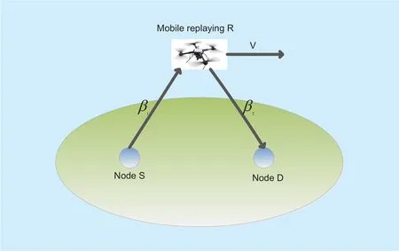
Fig. 1. A UAV-enabled full-duplex relaying system model.
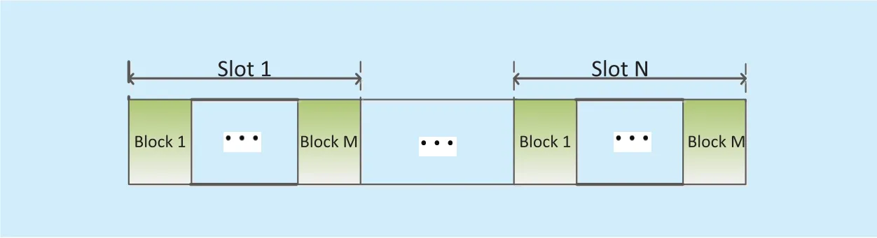
Fig. 2. Frame structure of the considered UAV-based relaying systems.
II. SYSTEM MODEL
In this paper, we investigate a single-antenna UAV-based relaying system where a single-antenna source node S and a single-antenna destination node D are both distributed in the ground. Furthermore, the location of node S and node D are fixed, and UAV travels along unidirectional trajectory as shown in figure 1.
In the full-duplex mode, the relay R can be able to transmit signal to node D and receive signal from node S simultaneous at the same frequency. Assume that the UAV-enabled relay has good computational ability and by utilizing some cancellation technologies, such as analog RF interference cancellation, antenna cancellation, which can suppress the self-interference to the noise floor [31]-[34]. Therefore,it is reasonable to assume that the self-interference is eliminated completely in relay node R.
2.1 The physical-layer signal and channel model
The period T is denoted as total flying time when UAV moves from launching location to landing location. For ease of exposition, the time T is equally divided into N time slots with each slot duration δ, i.e., T=Nδ. Note that δ should be sufficiently small so that the UAV’s location can be assumed to be constant within each time slot [30], [35].
We consider a narrowband transmission over quasi-static block fading channel in both S-R link and R-D link, i.e., the both channels are regarded as static during each block period. Moreover, we assume that channel coef ficient in each block is independent and changes from block-to-block, and the duration of each block is much smaller compared with slot δ,i.e, M≫1 as shown in Figure 2. Under this fading model, we denote the S-R and R-D channel coefficient at the m-th block of time slot n as hsr[n, m] and hrd[n, m], respectively. As such, the received signal at relay R and destination node D are respectively given by[12]
and

where x[ n, m] denotes the transmitted signal from node S with power Ps[ n ], and r[ n, m]denote the decoded signal with power Pr[ n ] at node R. Similarly as [36], a low-altitude UAV is adopted for relaying in cooperative communication, due to the higher altitude of UAV will resulting in the transmitted signal from UAV to destination node dramatically attenuated. The channel hij[n, m] with ij∈{sr, rd},is assumed to be independently circularly-symmetric complex Gaussian (CSCG) distributed. Thus, the probability density function(PDF) of exponential random variablecan be expressed as [37]
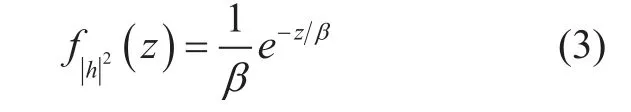
in which β∈{β1, β2} is the mean of the exponential random variable. Just similar as [12], [37], each channel power gain at time slot n is denoted asandwhich accounts for the large-scale channel attenuation that only depends on the link distance, here, dijis the link distance between node i and node j,and β0denotes the reference channel gain at d=1 m. Without loss of generality, we assume that noise zr[n]~ CN(0,σ02) and noise zd[n]~ CN(0,σ02) with the same variance.
2.2 Outage probability performance analysis
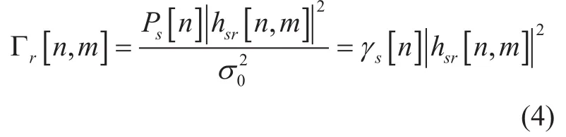
Using (1) and (2), the signal-to-noise ratio(SNR) at node R and node D at the m-th block of time slot n are respectively given by
And
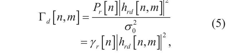
wheredenote the SNR at node S and node R, respectively.
Hence, the outage probability at time slot n can be expressed as follows [12],
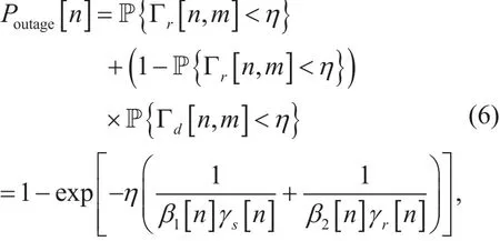
where η is the threshold SINR.
2.3 Problem formulation
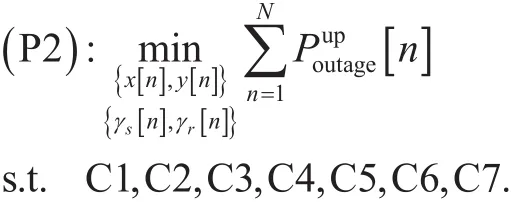
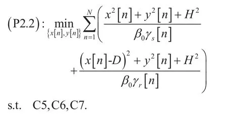
To make mathematical description simplicity,we consider a three-dimensional Cartesian coordinate system with all dimensions being measured in meters, where the node S and node D are located at (0,0,0) and (D,0,0),respectively. We assume that the UAV flies at a fixed altitude H, and the time-varying coordinate of the relay UAV can be expressed as (x[ n ],y[ n], H ) at time slot n,1≤n≤N.Then,andMoreover, we assume that the UAV’s launching location and landing location are fixed with(x0,y0, H ) and (xF,yF,H ), respectively. This corresponds to practical scenario where UAV executes a particular task. Thus, the minimum flight distance needs to be moved within time period T isNote that UAV flight speed V should be greater than, to guarantee that there exists at least one feasible trajectory from launching location to landing location.Moreover, the Doppler effect due to the relay’s mobility at relay and destination node are both assumed to be perfectly compensated[38]. In this paper, our objective is to minimize the sum outage probability from S to D by jointly optimizing source/relay poweras well as the relay trajecto-. Then, the problem can be formulated as follows where C1 and C2 represent the average power constraints over time T, withanddenoting the average power constraints at nodeand, respectively. C3 and C4 make sure power allocation at source and relay non-trivial. C5-C7 denote UAV trajectory constraints.Note that problem (P1) is non-convex due to the coupled powerand relay trajectoryin objective function, which can not be directly solved.
III. POWER AND TRAJECTORY OPTIMIZATION FOR UAV-BASED COOPERATIVE SYSTEMS
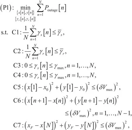
In this section, we consider joint power and trajectory optimization for outage probability minimization of relaying system. Follows from (6), it can be readily verified that the expression Poutage[n ] is a concave function with respect to. Recall that any concave function is globally upper bounded by its first-order Talyor expansion at any feasible point [39]. Therefore, the upper bound with given local point 0 follows that
Actually, the gap between Poutage[n] and[n] is tight, which is verified in section IV. As a result, the problem (P1) can be approximately solved by minimizing its upper bound function as
It can be easily verified that constraints set C1-C7 are all convex. However, problem(P2) is still non-convex due to the coupled power and trajectory constraints in objective function. It can be observed from (P2) that if relay trajectoryare fixed,the objective function is convex with respect to, and if power allocationare fixed, the objective function with respect toare also convex. Based on this fact, we propose an iterative algorithm, which later prove efficiently in simulation. Specifically, we first decompose the problem (P2) into two convex sub-problems to computeandseparately, and then solve two sub-problems alternatively. In the following sections, the threshold SNR η is omitted in objective function of (P2), which is still equivalent.
3.1 Power optimization with fixed trajectory
In this section, we consider the first sub-problem of (P2) for optimizing power allocationby assuming the relay trajectoryare fixed. The first sub-problem of (P2) can be written as
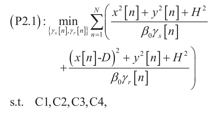
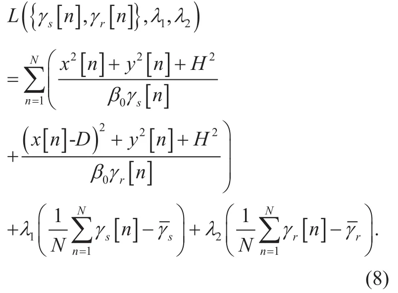
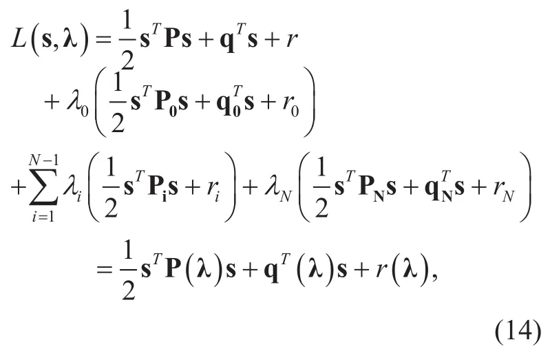
Although problem (P2.1) is convex with respect toand can be numerically solved by standard convex optimization techniques. Instead of relying on a generic solver, here we obtain optimal power allocation based on solving its corresponding Lagrange duality from [39], [40]. To this end, we first introduce the Lagrangian dual variables λ1≥ 0 and λ2≥ 0. Then, the corresponding Lagrangian of (P2.1) can be expressed as
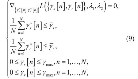
It is not difficult to verify that (P2.1) satisfies the Slater’s condition, thus optimal duality gap is zero. Therefore, any pair of primal and dual optimal points must satisfy the KKT conditions [39]. By applying KKT condition,the optimal Lagrange multipliersand optimal primal pointsare should satisfied the following constraints
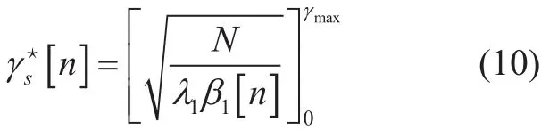
Follow from (9), the optimal source/relay powerwith given λ and λ12can be respectively obtained as
And
For solving the optimaland, the standard bisection method is employed which make sureand. Note that if UAV directly move from S to D, the β1[n] and β2[n] are respectively monotonically decreasing and increasing over time slot n, then the optimal power allocationandare monotonically increasing and decreasing over time slot n based on (10) and (11). The detailed Lagrangian-based procedures are summarized in Algorithm 1.
3.2 Trajectory optimization with fixed power allocation
In this section, we will discuss the second sub-problem of (P2), which we focus on optimizing relay trajectory with fixed power allocation. The second sub-problem of (P2) can be written as
Actually, (P2.2) is a quadratically constrained quadratic program (QCQP) problem,and by performing mathematical manipulations of (P2.2), (P2.2) can be reformulated in a standard QCQP form as follows
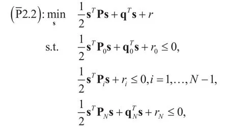
where the scalar value r, r0,and rNare given by∀i, andrespectively. The vector s, q, q0and qNdenote relay trajectory, relay power allocation, initial relay location and final relay location, which is given bya n d=[0,…,−2 xF,0,…,−2yF], respectively.
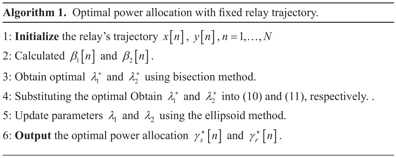
Algorithm 1. Optimal power allocation with fixed relay trajectory.1: Initialize the relay’s trajectory x[ n], y[ n],n=1,…,N 2: Calculated β1[n] and β2[n].3: Obtain optimal λ1★ and λ2★ using bisection method.4: Substituting the optimal Obtain λ1★ and λ2★ into (10) and (11), respectively. .5: Update parameters λ1 and λ2 using the ellipsoid method.6: Output the optimal power allocation γs★ [n] and γr★ [n].
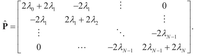
The dimension ofandare all 2N×2N. The Matrices A, A0and ANare the diagonal matrices of P, P0and PNwith dimension N×N, respectively. Where Matrices A, A0and ANare given by
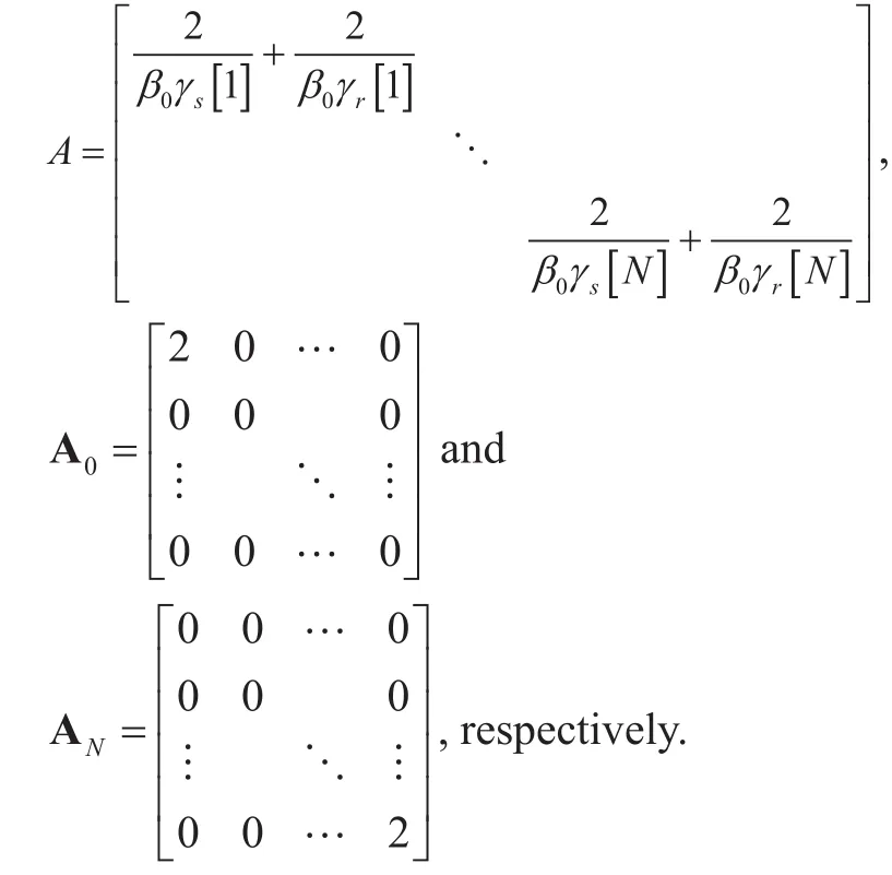
In addition, matrix
with i=1,…,N −1,
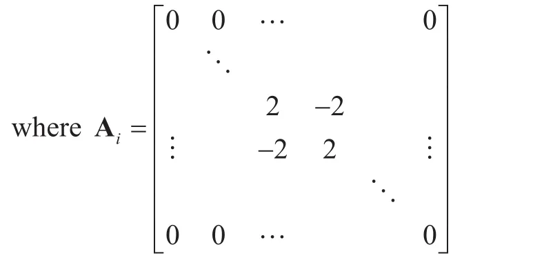
is the N×N diagonal matrix of Piwith nonzero block elements from row i to i+1 and column i to i+1 like above form.
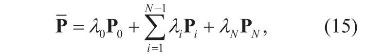
Theorem 1:The optimal relay trajectory solution to (2.2) is s★=− P−1(λ) q( λ), with the vector λ that maximizes the following dual problem :
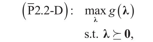
whereand q( λ), q( λ) as well as r(λ) are given in Appendix A.
Proof: Please refer to Appendix A.
Then, we can obtain the Lagrange multipliers in each iteration if subgradient of(2.2-D) at point λ is obtained. The update rules of λ is given as

where t, i and π1denote the iterative time,i th element of λ and step size, respectively.Note that g( λ) is a non-differentiable function due to involving the inversion of P( λ),which could not directly obtain ∇λ. Here,we resort to solving it using finite-difference method (FDM) [41], which can be calculated as
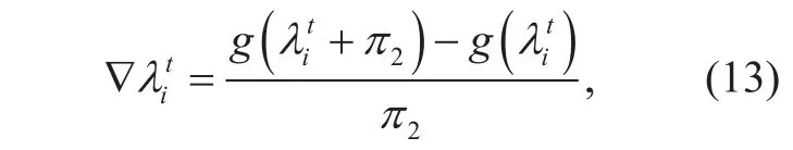
in which π2represents step size. The subgradient updates of (12) are guaranteed to converge the optimal λ★as long as step size π1and π2are chosen to be appropriate [39].As optimal vector λ★are obtained, then, substituting the optimal vector λ★into (17), the optimal relay trajectory s★is obtained. Note that relay trajectory s★is a global solution of(P2.2). The detailed procedures are concluded in Algorithm 2.
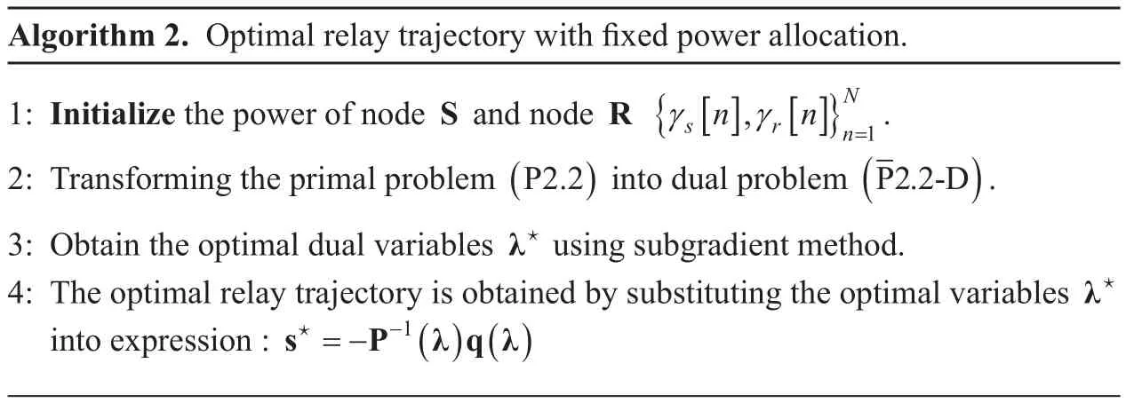
Algorithm 2. Optimal relay trajectory with fixed power allocation.1: Initialize the power of node S and node R {γ γ=1.2: Transforming the primal problem (P2.2) into dual problem s r[n], [n]}nN(P2.2-D).3: Obtain the optimal dual variables λ★ using subgradient method.4: The optimal relay trajectory is obtained by substituting the optimal variables λ★into expression : s P λ q λ★=− −1()()
Lemma 2:If the transmit power of UAV and node S at each slot keep invariant,i.e., γs[n]= γsand γr[n]= γr, meanwhile the period time T is sufficient large, i.e.,, the optimal UAV speed v[ n] satisfies
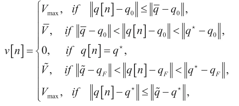
whereand the parameters q, q ,, q★,q[ n ] and V are given in Appendix B.
Proof: Please refer to Appendix B.
Lemma 2 shows that UAV speed equals to Vmax,,or 0. In addition, if, then V=0, where mod(a, b) denotes the reminder after division of a by b. Similarly, if, then=0.
Theorem 2:If the period time T is sufficient large, the optimal UAV trajectory q[ n]for minimizing sum outage probability is given as

where Ln= Vmaxδn ,= Vmaxδ(n −) and
Proof: Please refer to Appendix C.
3.3 Joint power and trajectory optimization
In this section, we propose an iterative algorithm for jointly optimizing power allocation and relay trajectory of problem (P2), which is provided in Algorithm 3. Note that for each iteration in Algorithm 3, problem (P2.1) and(P2.2) are all convex, thus each sub-problem’s solution is unique global optimal. Note that we cannot declare that the convergence results using Algorithm 3 are global optimal,however, local optimal solutions are guaranteed to Algorithm 3.
3.4 Convergence property and complexity analysis
Herein, a brief illustration of the convergence property of the proposed Algorithm 3 is discussed. At l-th iteration in step 3, with given UAV trajectory, the optimal power allocationare globally solved. Then, at step 4 of Algorithm 3, with given power allocationthe updated UAV trajectory, denoted as, are solved optimally by employing Algorithm 2. Therefore, Algorithm 3 is non-increasing over each iteration. In addition, the objective value of[n] is lower bounded by a finite value, Algorithm 1 is thus guaranteed to converge.
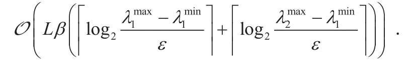
Next, we give the computational complexity of the proposed Algorithm 3 in details.According to proposed Algorithm 1, we adopt the bisection method to findand.Then, the computational complexity of the bisection for solvingandare respectively given byandwith maximal tolerance ε, wherewith i∈{1,2}.Denote the maximum iterations needed to update the Lagrangian dual variables as β,and the overall maximum iterative numbers in Algorithm 3 are denoted as L. Hence, the total complexity of the proposed Algorithm 3 is
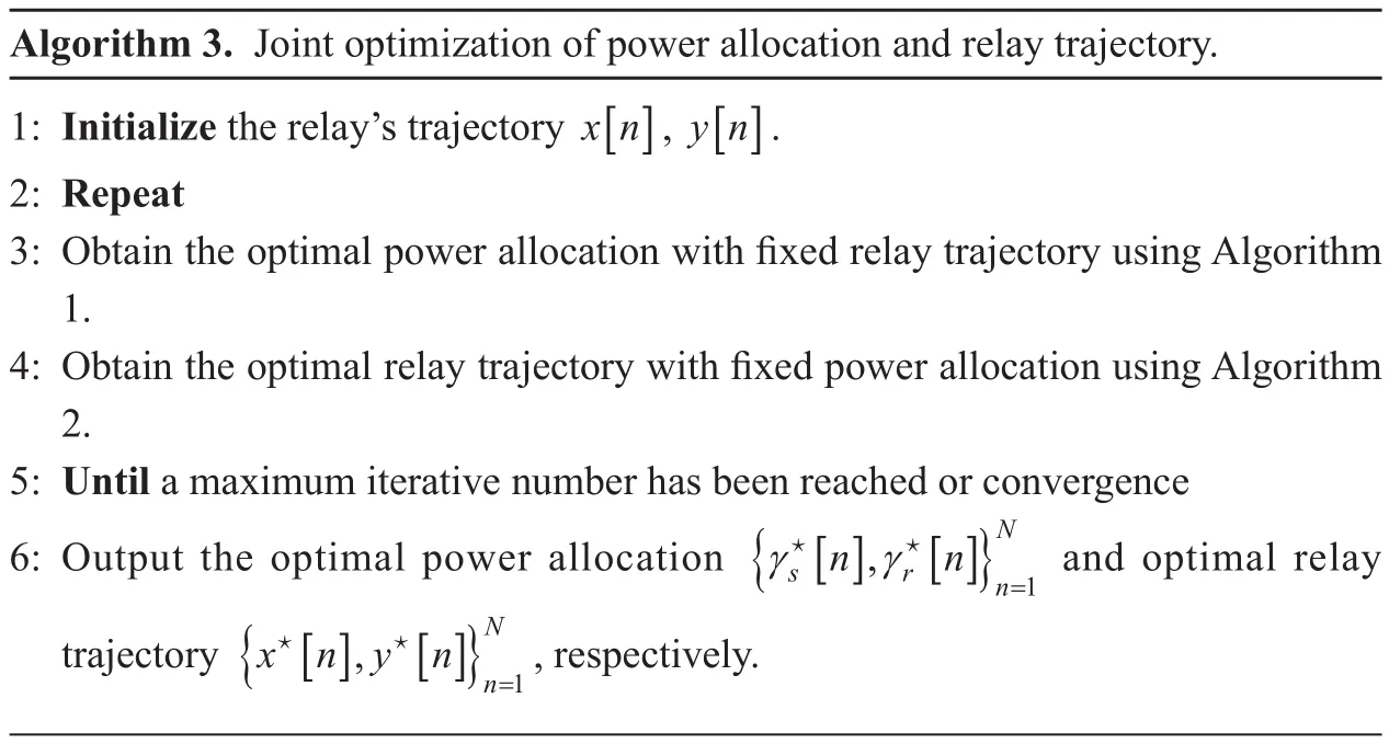
Algorithm 3. Joint optimization of power allocation and relay trajectory.1: Initialize the relay’s trajectory x[ n], y[ n].2: Repeat 3: Obtain the optimal power allocation with fixed relay trajectory using Algorithm 1.4: Obtain the optimal relay trajectory with fixed power allocation using Algorithm 2.5: Until a maximum iterative number has been reached or convergence 6: Output the optimal power allocation {γ γ=1 and optimal relay trajectory {x n y n★ ★N s r[n], [n]}n★ ★[], []}nN=1, respectively.
It is worth noting that the maximum number of iterations L in algorithm is 2 by simulation,which is given in section IV.
IV. NUMERICAL RESULTS
In this section, numerical results for UAV-enabled full duplex DF mobile relaying systems are provided to verify our proposed scheme benefits.
Unless otherwise stated, we set the system transmission target rate R=0.5bpsHz, which correspond to the threshold SNR η=0.4142.The noise power spectrum density and channel gain β0are −110dBm and −50dB with bandwidth per link 1MHz. The distance between node S and node D is D=100m,and each time slot duration δ is set to 0.5s.The UAV’s flying altitude is set to H=10m,which correspond to minimum UAV’s flying altitude for being avoided by mountainous area, and the maximum UAV flying speed is 10m s. The UAV’s launching location and landing location are set to (20,500,H) and(80,500,H), respectively. In addition, the average transmit power of source and relay are both set to 10dBm, and the maximum transmit power of source and relay are set to four times of average transmit power [42].
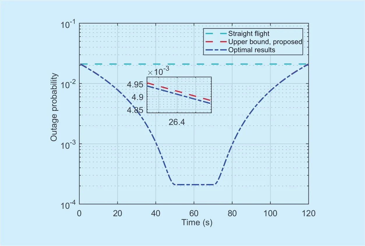
Fig. 3. Outage probability versus time slot with T=120s.
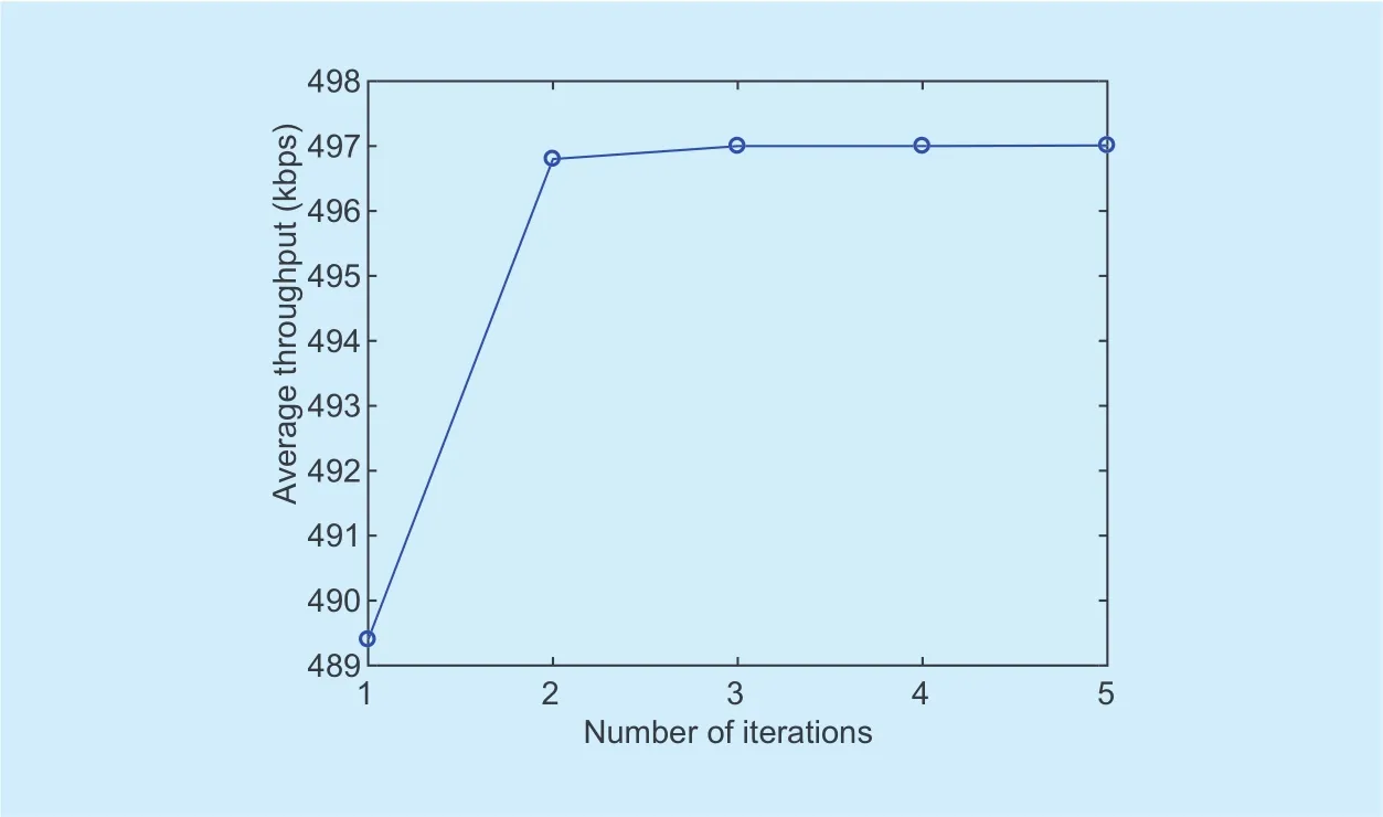
Fig. 4. Convergence behavior of the proposed Algorithm 3.
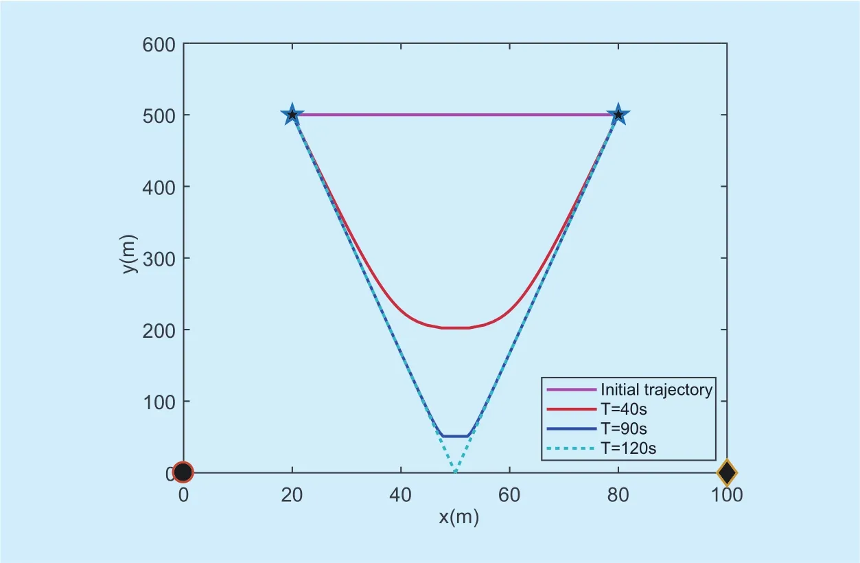
Fig. 5. Optimal Trajectory with different block length T.
Figure 3 compares the proposed scheme with traditional straight flight scheme in terms of minimizing the sum outage probability. It is firstly observed that the solution of[n ]obtained by proposed algorithm is quite close to the solution of Poutage[n], which means that the original function Poutage[n] is tight to[n ]. In addition, the outage probability[n] firstly monotonically decreases with time slot n, next keep invariant for a while,and then monotonically increases with time slot n. This result can be explained from Theorem 2, UAV attempts to move close to optimal location, then will hover about the optimal location, and will leave due to the limited time. The more detailed insights are provided in Figure 5. Besides, traditional straight flight,which have no trajectory optimization and power allocation, our proposed scheme is superior to straight flight scheme for minimizing the sum outage probability.
In Figure 4, the behavior of the proposed Algorithm 3 is plotted. It can be observed that the convergence can be quickly achieved with only two number of iterations, which verifies the effective of our proposed scheme.
Figure 5 depicts different relay trajectory with different block length T with our proposed algorithm. At time T=40s, due to the limited time, UAV will not reach the optimal location, which can observed from red curve.As time T become larger, UAV will arrive at optimal location, then will hover above as long as possible for providing wireless service, which demonstrates the effectiveness of Theorem 2.
In Figure 6, we plot the source/relay power allocation obtained by our proposed method corresponding to T=120s. We can observe that the transmission power of source node and UAV both increase as the time increase initially and decrease afterwards. This can be attributed to the fact that the distance of S−R link and R−D link first decrease as time increase and then increase as shown in Figure 5. Then, from formulas (10) and (11), we can easily obtain the results. To gain more insight,the curve of variation-speed of UAV is plotted in Figure 7 at time T=120s. We can observe from that, in the first phase, UAV flies at the maximum speed, then, flies with constrained speed, and will hover above for staying, which also verifies the effectiveness of Lemma 2. In the second phase, the UAV speed is similarly to the first phase, and is omitted for brevity.
Figure 8 compares the performance of our proposed scheme with two benchmarks for maximizing average throughput versus different block length T. Basically speaking, the average throughput is monotonically increasing with period T by our proposed scheme. It also can be observed that as period T is suffi-cient large, our proposed scheme will achieve optimal solution. Besides, our proposed scheme outperforms the straight flight scheme,and performance gain is more pronounced as T increases.
V. CONCLUSIONS
In this paper, we investigated a UAV-enabled full-duplex DF for cooperative communication in mobile relaying systems. The transmit power of source/relay and UAV trajectory were jointly optimized for minimizing sum system outage probability. Specifically, with the pre-determined UAV trajectory, the optimal transmit power of source and relay schemes were obtained by solving KKT conditions.Then, with given power allocation, the optimal UAV trajectory was obtained via solving dual problem of standard QCQP. Based on above two algorithms, an iterative algorithm was proposed for jointly optimizing source/relay power allocation and UAV trajectory alternately. In addition, the closed form of optimal UAV trajectory was obtained as time T becomes larger. Numerical results showed that our proposed scheme outperforms the pre-determined relay trajectory in terms of the outage probability. In addition, our proposed scheme would achieved maximum average throughput as period T increases.
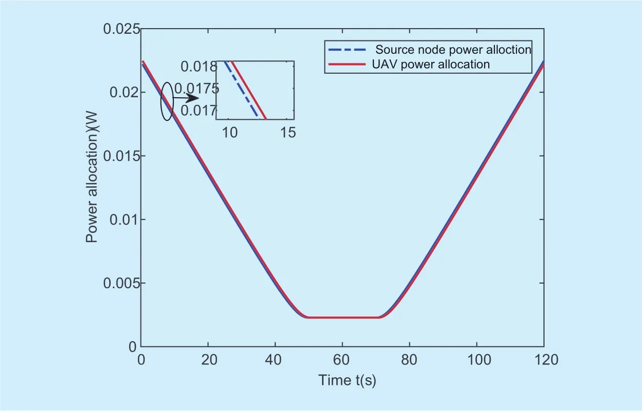
Fig. 6. Source/relay power allocation obtained by our proposed method corresponding to T=120s.
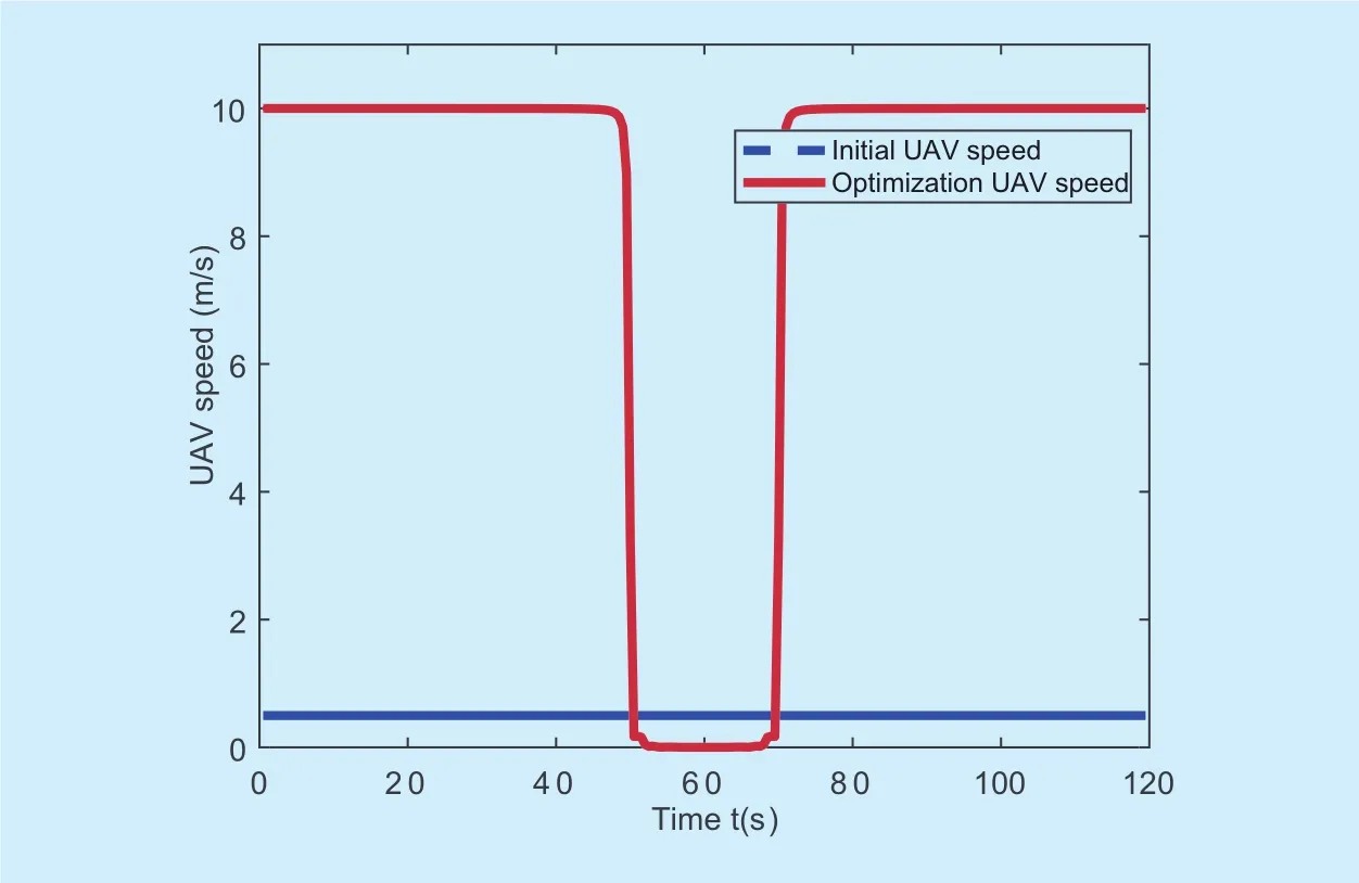
Fig. 7. The speed of UAV at T=120s.
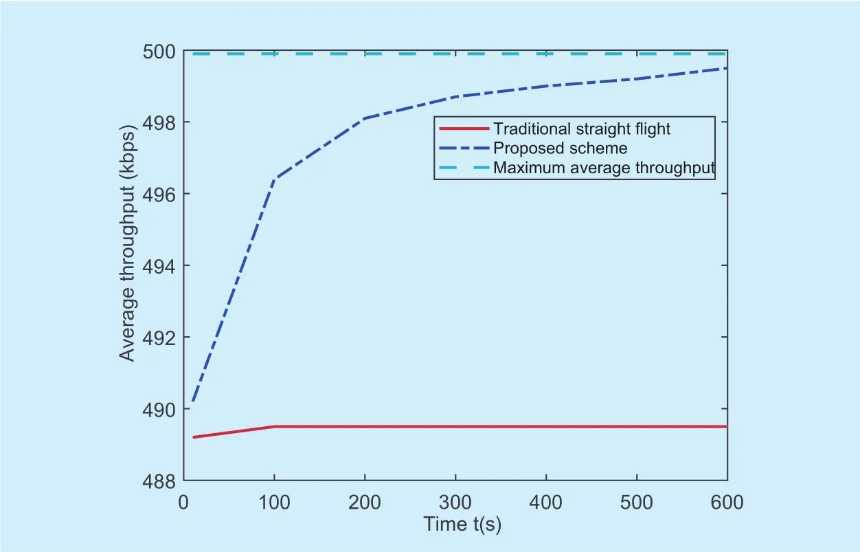
Fig. 8. Average throughput versus different block length T with different schemes.
APPENDIX A PROOF OF THEOREM 1
By introducing Lagrangian dual variables λ≥0, then, the Lagrangian function of(P2.2) can be expressed as
in whichand
Lemma 1:P( λ) is positive definite matrix with λi≥ 0,γr[n] >0 and γs[n ]>0,∀n , i.
Proof: First, it can be observed from(14) that P( λ) is symmetric matrix, due to P, P0, Piand PNare all symmetric. Next, we define
then,can be reformulated asin whichis given by
For the vector, the formula
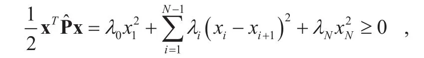
where xT=[x1, x2,… xN], which meansis a positive semi-definite matrix. It is not difficult to verified that the matricesandhave same eigenvalues, whereas the number of eigenvalues ofandare not same. Moreover, due to the fact P is positive definite matrix, as a result,P( λ )= P +is positive definite matrix. This thus completes proof of Lemma 1.
Next, Lagrange dual function of (P2.2) is reformulated as follows
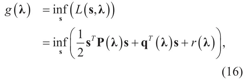
with Lemma 1, P( λ) is positive definite matrix, by taking first derivative of (16) at point s, we can obtain the optimal s★as

then, substituting this optimal vector s★in(16), we can obtain dual function of (2.2) as
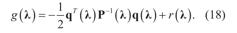
If the optimal vector λ★is obtained for maximizing (18), then the optimal relay trajectory s★is obtained via substituting λ★into(17). This thus completes proof of Theorem 1.
APPENDIX B PROOF OF LEMMA 2
Ifwhich indicates that there must exist one direct feasible path from initial location q0to q★, and q★to final location qF, and meanwhile ensuring UAV hover above q★for at least one time slot, where q★represents optimal location of UAV. For mathematical description simplicity, we define
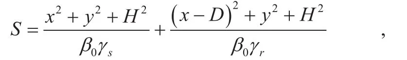
where x[ n] and y[ n] are regarded as continuous variable by omitting n. Taking first partial derivative of objective function of S with respect to x and y, it follows that
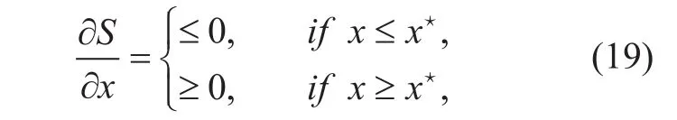
and
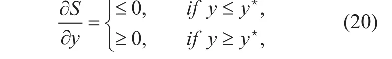
where. It can be ac-cordingly conclude that x★is optimal solution to S with given y, and y★is optimal solution to S with given x. In addition, S is a concave function with trajectory x and y, thus,are the global solution to S. Therefore, the search directions must be chosen to the steepest descent direction from q0to q★and q★to qF, in whichand
For ease of exposition, we divide the whole UAV travel phase into two phases. In the first phase, we consider UAV trajectory from q0to q★. Based on the analysis above, the maximum UAV speed must be chosen to shorten the distance between UAV location and optimal location q★at time slot n if possible. It is worth noting that if UAV is nearby optimal location,i.e.,in whichwithin the next time slot n+1, the UAV speed is equal to. As UAV arrives at optimal location q★, UAV will hover above optimal location as long as possible if time is allowed. In the second phase, similarly manipulations are performed and is omitted here for brevity. This thus completes the proof of Lemma 2.
APPENDIX C PROOF OF THEOREM 2
In the similarly way as stated in Appendix B,we decompose the whole UAV travel phase into two phases, i.e., from q0toand fromto qF, respectively. In the first stage, time slot n satisfiesIt follows that Lemma 2, UAV moves from q0towith maximum speed, then moves fromto q★with speed. If time is allowed, UAV will hover above q★with speed 0. When time is not available, i.e.,,UAV will move from q★to~ with speed, and then moves fromto q0with maximum speed.Based on above analysis, the optimal UAV trajectory could be directly achieved. This thus completes the proof Theorem 2.
ACKNOWLEDGEMENT
This work was supported by National High Technology Project of China 2015AA01A703,Scientific and Technological Key Project of Henan Province under Grant 182102210449,the National Natural Science Foundation of China under Grants 61372101 and 61671144.
[1] J. Gan, Z. Guo, K. Sandlund, and J. Liu, “Lte inband relay prototype and field measurement,”in Vehicular Technology Conference, 2012,pp.1–5.
[2] K. Song, C. Li, Y. Huang, and L. Yang, “Antenna selection for two-way full duplex massive mimo networks with amplify-and-forward relay,” Science China Information Sciences, vol. 60, no. 2,p. 022308, 2016.
[3] J. N. Laneman, D. N. C. Tse, and G. W. Wornell,“Cooperative diversity in wireless networks:Efficient protocols and outage behavior,” IEEE Transactions on Information Theory, vol. 50, no.12, pp. 3062–3080,2004.
[4] Y. Zhao, R. Adve, and J. L. Teng, “Improving amplify-and-forward relay networks: Optimal power allocation versus selection,” in IEEE International Symposium on Information Theory,2006, pp. 1234–1238.
[5] A. Nosratinia, T. E. Hunter, and A. Hedayat, “Cooperative communication in wireless networks,”IEEE Communications Magazine, vol. 42, no. 10,pp. 74–80, 2004.
[6] W. Zhang, D. Duan, and L. Yang, “Relay selection from a battery energy efficiency perspective,”IEEE Transactions on Communications, vol. 59,no. 6, pp. 1525–1529, 2009.
[7] R. Pabst, B. H. Walke, D. C. Schultz, P. Herhold, H.Yanikomeroglu, S. Mukherjee, H. Viswanathan,M. Lott, W. Zirwas, and M. Dohler, “Relay-based deployment concepts for wireless and mobile broadband radio,” in IEEE Communications Magazine, Volume 42, Issue 9, Sept. 2004 Page(s):80, 2004, pp. 80 – 89.
[8] L. Fan, R. Zhao, F. K. Gong, N. Yang, and G. Karagiannidis, “Secure multiple amplify-and-forward relaying over correlated fading channels,” IEEE Transactions on Communications, vol. PP, no.99, pp. 1–1, 2017.
[9] L. Fan, X. Lei, N. Yang, T. Q. Duong, and G.K. Karagiannidis, “Secure multiple amplify-and-forward relaying with cochannel interference,” IEEE Journal of Selected Topics in Signal Processing, vol. 10, no. 8, pp. 1494–1505,2016.
[10] M. Jain, J. I. Choi, T. Kim, D. Bharadia, S. Seth, K.Srinivasan, P. Levis, S. Katti, and P. Sinha, “Practical, real-time, full duplex wireless,” in International Conference on Mobile Computing and NETWORKING, 2011, pp. 301–312.
[11] M. Duarte and A. Sabharwal, “Full-duplex wireless communications using off-the-shelf radios:Feasibility and first results,” in Signals, Systems and Computers, 2010, pp. 1558–1562.
[12] B. Yu, L. Yang, X. Cheng, and R. Cao, “Power and location optimization for full-duplex decode-and-forward relaying,” IEEE Transactions on Communications, vol. 63, no. 12, pp. 4743–4753, 2015.
[13] H. Xie, F. Gao, S. Zhang, and S. Jin, “A unified transmission strategy for tdd/fdd massive mimo systems with spatial basis expansion model,”IEEE Transactions on Vehicular Technology, vol.66, no. 4, pp. 3170–3184, 2017.
[14] H. Xie, F. Gao, and S. Jin, “An overview of lowrank channel estimation for massive mimo systems,” IEEE Access, vol. 4, pp. 7313–7321, 2016.
[15] W. Cho and L. Yang, “Resource allocation for amplify-and-forward relay networks with differential modulation,” in International Conference,New2an and Russian Conference on Smart Spaces, Rusmart on Next Generation Teletraffic and Wired/wireless Advanced NETWORKING,2008, pp. 88–100.
[16] M. O. Hasna and M. S. Alouini, “Optimal power allocation for relayed transmissions over rayleigh fading channels,” in Vehicular Technology Conference, 2003. Vtc 2003-Spring. the IEEE Semi, 2003, pp. 2461–2465 vol.4.
[17] R. Cao and L. Yang, “The affecting factors in resource optimization for cooperative communications: A case study,” IEEE Transactions on Wireless Communications, vol. 11, no. 12, pp.4351–4361, 2012.
[18] B. Yu, L. Yang, X. Cheng, and R. Cao, “Relay location optimization for full-duplex decode-and-forward relaying,” in MILCOM 2013 –2013 IEEE Military Communications Conference,2013, pp. 13–18.
[19] A. Qiantori, H. Hariyanto, H. Suwa, and T. Ohta,“An emergency medical communications system by low altitude platform at the early stages of a natural disaster in indonesia,” Journal of Medical Systems, vol. 36, no. 1, p. 41, 2012.
[20] E. W. Frew and T. X. Brown, “Airborne communication networks for small unmanned aircraft systems,” Proceedings of the IEEE, vol. 96, no.12, pp. 2008–2027, 2009.
[21] Y. Zeng, R. Zhang, and J. L. Teng, “Wireless communications with unmanned aerial vehicles: opportunities and challenges,” IEEE Communications Magazine, vol. 54, no. 5, pp. 36–42, 2016.
[22] Q. Wu, Y. Zeng, and R. Zhang, “Joint trajectory and communication design for multi-uav enabled wireless networks,” arXiv preprint arXiv:1705.02723, 2017.
[23] D. Yang, Q. Wu, Y. Zeng, and R. Zhang, “Energy trade-off in ground-to-uav communication via trajectory design,” arXiv preprint arX-iv:1709.02975, 2017.
[24] J. Zhao, F. Gao, Q. Wu, S. Jin, Y. Wu, and W. Jia,“Beam tracking for uav mounted satcom onthe-move with massive antenna array,” arXiv preprint arXiv:1709.07989, 2017.
[25] J. Zhao and W. Jia, “Channel transmission strategy for mmwave hybrid uav communications with blockage,” Electronics Letters, vol. 54, no.2, pp. 74–76, 2017.
[26] C. Li, Y. Li, K. Song, and L. Yang, “Energy efficient design for multiuser downlink energy and uplink information transfer in 5g,” Science China Information Sciences, vol. 59, no. 2, pp. 1–8,2016.
[27] C. Li, K. Song, D. Wang, F.-C. Zheng, and L.Yang, “Optimal remote radio head selection for cloud radio access networks ł,” Science China Information Sciences, vol. 59, no. 10, p. 102315,2016.
[28] M. Mozaffari, W. Saad, M. Bennis, and M. Debbah, “Optimal transport theory for power-effi-cient deployment of unmanned aerial vehicles,”in Proc. of IEEE International Conference on Communications (ICC), 2016.
[29] M. Mozaffari, W. Saad, M. Bennis, Merouane,and Debbah, “Mobile internet of things: Can uavs provide an energy-efficient mobile architecture?” in Proc. of IEEE Global Communications Conference (GLOBECOM), 2016.
[30] Y. Zeng, R. Zhang, and J. L. Teng, “Throughput maximization for uavenabled mobile relaying systems,” IEEE Transactions on Communications,vol. PP, no. 99, pp. 1–1, 2016.
[31] E. Everett, D. Dash, C. Dick, and A. Sabharwal,“Self-interference cancellation in multi-hop full-duplex networks via structured signaling,” in Communication, Control, and Computing, 2012,pp. 1619–1626.
[32] T. Riihonen, S. Werner, and R. Wichman, “Mitigation of loopback self interference in full-duplex mimo relays,” IEEE Transactions on Signal Processing, vol. 59, no. 12, pp. 5983–5993, 2011.
[33] S. Li and R. D. Murch, “Full-duplex wireless communication using transmitter output based echo cancellation,” vol. 14, no. 12, pp. 1–5, 2011.
[34] R. Zhang, X. Cheng, Q. Yao, C. X. Wang, Y. Yang,and B. Jiao, “Interference graph-based resource-sharing schemes for vehicular networks,”IEEE Transactions on Vehicular Technology, vol.62, no. 8, pp. 4028– 4039, 2013.
[35] S. Jeong, O. Simeone, and J. Kang, “Mobile cloud computing with a uav-mounted cloudlet:optimal bit allocation for communication and computation,” Iet Communications, vol. 11, no.7, pp. 969–974, 2017.
[36] S. Mori, “Cooperative sensing data collecting framework by using unmanned aircraft vehicle in wireless sensor network,” in IEEE International Conference on Communications, 2016, pp. 1–6.
[37] A. A. Nasir, X. Zhou, S. Durrani, and R. A. Kennedy, “Relaying protocols for wireless energy harvesting and information processing,” IEEE Transactions on Wireless Communications, vol.12, no. 7, pp.3622–3636, 2013.
[38] U. Mengali and A. N. DAndrea, “Synchronization techniques for digital receivers,” Applications of Communications Theory, 1997.
[39] S. Boyd and L. Vandenberghe, Convex Optimization, 2013.
[40] A. Antoniou and W. S. Lu, Practical Optimization: Algorithms and Engineering Applications.Springer Publishing Company, Incorporated,2010.
[41] J. P. Wright and M. L. Baron, “A survey of finite-difference methods for partial differential equations,” Numerical & Computer Methods in Structural Mechanics, pp. 265–289, 1973.
[42] G. Zhang, Q. Wu, M. Cui, and R. Zhang, “Securing uav communications via joint trajectory and power control,” arXiv preprint arXiv:1801.06682,2018.
杂志排行

China Communications的其它文章
- Geometric Mean Decomposition Based Hybrid Precoding for Millimeter-Wave Massive MIMO
- Outage Performance of Non-Orthogonal Multiple Access Based Unmanned Aerial Vehicles Satellite Networks
- Optimal Deployment Density for Maximum Coverage of Drone Small Cells
- Energy Efficient Multi-Antenna UAV-Enabled Mobile Relay
- Energy-Efficient Trajectory Planning for UAV-Aided Secure Communication
- An Enhanced Direct Anonymous Attestation Scheme with Mutual Authentication for Network-Connected UAV Communication Systems