Modeling Method and Control Strategy for Hose-Drogue Aerial Refueling System
2018-05-25,,,
, , ,
1.Navigation Research Center,Nanjing University of Aeronautics and Astronautics,Nanjing 210016,P.R.China;
2.Department of Automation of Nanhang Jincheng College,Nanjing 211156,P.R.China
0 Introduction
With the rapid integration of unmanned aerial vehicles(UAVs)into modern military operations,autonomous aerial refueling(AAR)has attracted increasing interests from many research institutions and scientific laboratories.There are two typical AAR methods,the flying-boom refueling (FBR)and the probe-drogue refueling(PDR)[1].PDR is able to refuel multiple aircrafts simultaneously with low cost and simple way.In PDR,a tanker aircraft deploys a flexible hose behind it with a drogue on the end of the hose,and its dorking phase is affected by tanker wake atmospheric turbulence and receiver fore-body.PDR requires skillful pilots to maneuver a thin probe into a moving drogue with a small diameter at an acceptable closure rate.It has always been a challenging operation for both manned and unmanned missions because of mishaps and damages easily caused by any tiny deviation.It is essential to improve PDR process to enhance the safety of both tanker and receiver.Therefore,the research on dynamic modeling and active control plays an important part in the AAR technology[2].
There are three approaches in PDR dynamic modeling:Partial differential equation method,finite element method based on mechanics of materials,and lumped parameter principle with rigid link kinematics.The former two are complex,with a large amount of calculation,which could hardly meet real-time requirement.Kamman et al[3-5].studied the modeling and simulation work of PDR for many years who have gained signifi-cant achievements.They presented a hose-drogue assembly model with a series of rigid links connected with frictionless ball-and-socket joints based on lumped mass,finite segment method.This model preferable reflected the dynamic behavior of hose-drogue system but the length of hose is constant.Hu et al[6-7].took the hose as a particle system,and calculated the hose balance position in terms of static equilibrium conditions,and studied the motion of hose-drogue influenced by atmospheric turbulence.Wanget al[8].proposed a variable length of multi-level ideal simple pendulum model based on Kamman′s work,and carried out comprehensive analysis of the features of hose-drogue system.Nevertheless,the methods above adopt newtonian mechanics method and need additional constraints to calculate internal force.Wei et al[9-11].studied the relationship between the drogue position and interference forces due to receiver fore-body based on a link-connected model and analyzed the drogue dynamic characteristics qualitatively based on system identification method,and proposed a lower order dynamic model to describe drogue dynamics under the bow wave effect.
Obviously,these studies,as well as the reports of flight tests,pointed out that the drogue position is susceptible to disturbances consisting of atmospheric turbulence,trailing vortex of the tanker and bow wave effect caused by the receiver.Among them,the receiver bow wave has a minimal effect on the drogue position compared to tanker wake and atmospheric turbulence[12].And the drogue motion is turned out to be instability especially in the atmospheric turbulence.The instability is able to cause an unpredictable drogue movement and increases the difficulty of a successful AAR operation.Hence,it is essential to stabilize the drogue in the presence of disturbance.The active control issues in the new context have been raised and initially investigated by some researchers.Kuk et al.[13-14]developed an active drogue stabilization approach by installing a set of four foldable wings around the rear hub cap and performed comprehensive dynamic wind tunnel experiments with a scale model prototype manufacturing,also implemented a feedback control law to avionics hardware design.Williamson et al.[15]presented a controllable drogue equipped with canopy materials attached to the end of the strut-arm basket to generate required side force.Moreover,a control law was executed to attenuate effects due to offsets from a desired position.Liu et al.[16]proposed a boundary control scheme based on Lyapunov′s direct method to regulate the hose′s vibration and designed a disturbance observer to estimate the input disturbance.Wang et al[17]designed an integral sliding mode backstepping controller for the hose whipping phenomenon relying on a permanent magnet synchronous motor and high-precision position sensors.Since all these concepts are feasible propositions lack of practical design details in the public domain,the control strategy for the hose-drogue system deserves our further exploration.
This paper is based on our previous work[18]and is distinguished from it.We propose a hosedrogue dynamic model.The main differences between them are as follows:(1)The restoring moment is taken into account for more exact external force analysis;(2)apart of the formula of force expression is written in vector form for more explicit;(3)conceptual active control strategies using both PID and LQR methods for the hose-drogue system are investigated based on the hose-drogue dynamic model,and the control effects are well compared.
1 Method and System Description
1.1 Principle of Kane method
Kane equation method provides a unified formula to solve the problem of rigid multi-body dynamics without requiring solution of the constraints equations,which is better at formulating equations of motion for complex mechanical system than classical approaches such as Newton method.Kane equation method employs generalized velocities to depicted the system,which are a group of variables independent from each other and can be used to uniquely define the velocities and angular velocities of the system.The number of generalized velocities equals to that of independent dynamical equations,as well as the degrees of freedom (DoFs)of the system[19-20].
For a system withnrigid bodies andmDoFs,Kane equation can simply be expressed as a set of scalar equations

where,Frandrepresent the generalized active force and the generalized inertia force of the system with respect to generalized velocityur,respectively,which can be expressed as
wherekstands for the index of rigid bodies.Fk(Mk)and()represent the active force(moment)and the inertia force(moment)acting on the bodyk,respectively;Vk,r=Vk/urthe partial velocity;andωk,r=ωk/ur,means the partial angular velocity of the bodykwith respect to the generalized velocityur;Vkthe velocity of mass center of bodyk,andωkthe angular velocity.
1.2 System description
In terms of lumped parameter method,the hose-drogue system is formulated under the following assumptions:(1)The hose is modeled as a series of constant length finite number of cylindrical shaped rigid bars connected with frictionless spherical joints;(2)the quality and external loads associated with each hose-bar are focused on the joints;(3)there is no rotation motion around central axis of hose due to the material characteristic of hose and exterior structure of bars;(4)the drogue is regarded as a mass point at the end of the hose.And the refueling pod moving with the tanker under the straight and level flight condition is connected with the other end of the hose.
The hose-drogue system dynamic model and coordinate systems are showed in Fig.1,whereSgrepresents an inertial reference frame in which the system moves;Spthe trajectory frame of the tanker;Skbar frame of each hose-bar.In Fig.1,the originOklocates in the mass center of each hose-bar.Xkpoints to the tanker along the symmetry axis of bar;Ykis orthogonal to symmetry plane and points right;Zkpoints down in the symmetry plane.Based on the assumptions above and frames defined,there are two state arguments used to depict the relative position between each hose-bar and the tanker:Relative pitch angleθk1(the angle between the projection ofOkXkin the plane ofOpXpZpandOpXpin trajectory frame with downward as positive),and relative yaw angleθk2(the angle betweenOkXkand the plane ofOpXpZpin trajectory frame with left deviation as position).
According to the angles defined and the coordinate systems,the coordinate transformation matrices amongSpandSkcan be obtained from
As suggested above,the hose-drogue system is assumed to benlevel rigid bars connected to each other.Taking the typical hose-barkfor consideration,its spatial position can be depicted byθk1andθk2.So the pose of the hose-drogue system can be expressed with number of 2nof independ-ent generalized velocities expressed as
2 Dynamic Model Formulation
2.1 Kinematics analysis
As shown in Fig.1,the length of each hosebar is assumed to be constantlk,andpkmeans the distance vector from hose-bar(k-1)pointing to hose-bark.SopkinSpcan be defined as
whereCki=cosθki,Ski=sinθki(i=1,2).The position vector of hose-barkin the trajectory frame can be expressed as
AsSpand the refueling pod move,it is feasible to seek the position of all hose-bars by Eqs.(4),(5),respectively.
Then,the velocity and acceleration of hosebarkinSpcan be found by the first and the second differentiating as
whereωkandαkare the angular velocity and angular acceleration of hose-barkinSp,defined as

2.2 Parameters calculation for Kane equation
2.2.1 Partialvelocityandpartialangularvelocity
Converting the velocity and angular velocity of hose-barkinto the form of generalized velocity inSpas

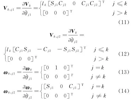
The partial velocityVk,j1,Vk,j2and partial angular velocityωk,j1,ωk,j2are calculated as follows
2.2.2 Inertiaforceandinertiamoment
Based on the state vectors defined above,the inertia force and inertia moment can be calculated in frameSpbelow.
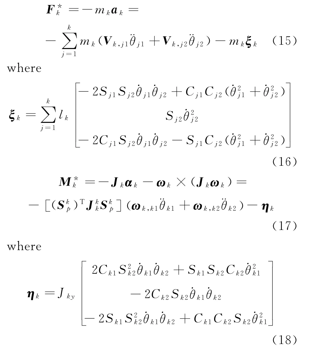
In Eq.(17)Jkkis the inertial matrix of hosebarkinSk.Assuming that the axial elementJkxof each hose-bar is zero due to the diameterdkfar less than the lengthlk.Additionally,considering the axial symmetry of the configuration of the hose-bar,JkyandJkzare taken as the same values.The similar matrix form is used to denote the inertia matrix of the drogue since it is also axisymmetric.But its axial elements are finite value.
2.2.3 Externalforceanalysis
The resultant external forceFkacting on the center of gravity of hose-bark,consisting of both gravitationalmkg,restoring moment due to hose bendingRkand aerodynamic forceDk,is

A restoring moment within the hose that tends to straighten emerges when the hose is bent due to an applied forces,which can be modeled based on a simple beam theory.As Fig.2shows,a bent hose is represented by two adjacent hosebars,and the hose restoring force can be treated as an equivalent external forceR[21].

Fig.2 Hose bent restoring force equivalent modeling
k
The magnititude of the forceRkacting on hose-barkcan be written as

whereIis the area moment of inertia of the hose′s cross section andEthe modulus of elasticity;lthe length of the hose-bars.They are calculated as

wheredo(di)is the outside(inside)diameter of the hose.
The force ofRkis in the plane spanned by the hose-bar vectorspkandpk+1with the direction of
Dkis composed ofDt,kandDn,kthat are tangential and normal aerodynamic drag separately,which are computed as[4]
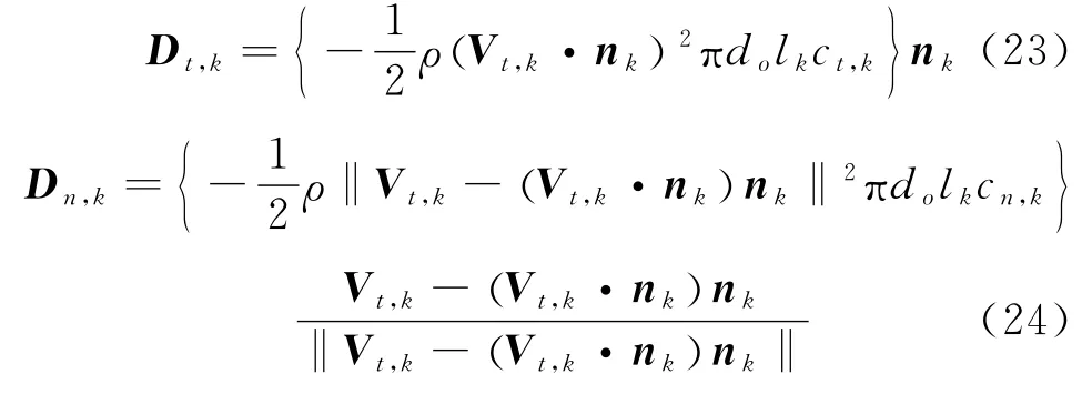
wherenk= [Ck1Ck2Sk2-Sk1Ck2]T,ρrepresents the air density;Vt,k=Vk-uk,ukthe local air velocity which is dependent upon the tanker wake,steady flow as well as atmospheric turbulence.The air velocity relative to the tanker wake can be modeled using a Hallock-Burnham model[22-23];ct,kandcn,krepresent the tangential and normal drag coefficients,which are involved with the Reynolds number of the local flow.Generally,they are obtained from experimental data.
The drogue is connected at the end of the hose,which is suffered the gravitationalmdrogand aerodynamic forceDdroas well.So the resultant external force of thenth hose-bar is

The drag of the drogue can be computed as

whereddrois the diameter of drogue andcdrothe drag coefficient of the drogue which depends on the drogue′s geometric characteristics.
2.2.4 Dynamicsequationsofsystem
Substituting the partial velocity and partial angular velocity expressions along with the accelerations,angular velocities and angular accelerations obtained in Eqs.(11)—(26)into Eq.(2)gives a set of 2nnumber 2nd order nonlinear differential equations.

whereurare the derivative of generalized velocities,Hprthe functions of generalized coordinates,masses and inertia matrixes of each hose-bar and drogue,Rpthe functions of generalized velocities and active forces,besides those ofHpr.Arranging these equations into a matrix form for computer simulation,the matrix[Hpr]2n×2nis invertible,so that these equations are readily to be solved.
2.3 Validation of the model accuracy
2.3.1 Numericalsolutionprocedure
Given that the physical and geometrical information of the hose-drogue system and motion parameters of the tanker as well as the initial angles of all hose-bars are known,the motion of the hose-drogue system may be tracked by the following steps.
(1)Define generalized coordinates and velocities,and set initial values;
(2)Compute the spatial position,velocity and angular velocity of each hose-bar;
(3)Compute the partial velocity and partial angular velocity with respect to each generalized velocity;
(4)Compute resultant extent force of each hose-bar;
(5)Establish Kane dynamic equations and solve with fourth-order fixed-step Runge-Kutta method;
(6)Compute the real-time position of drogue in inertial frame.
2.3.2 Steady-statecharacteristics
On account of the dynamic model put forward in the previous section,the simulation program is developed.The towing point of hose is assumed to be at the midspan of the tanker′s right wing,and the hose is apart into 20segments.The values of simulation parameters needed are shown in Table 1.
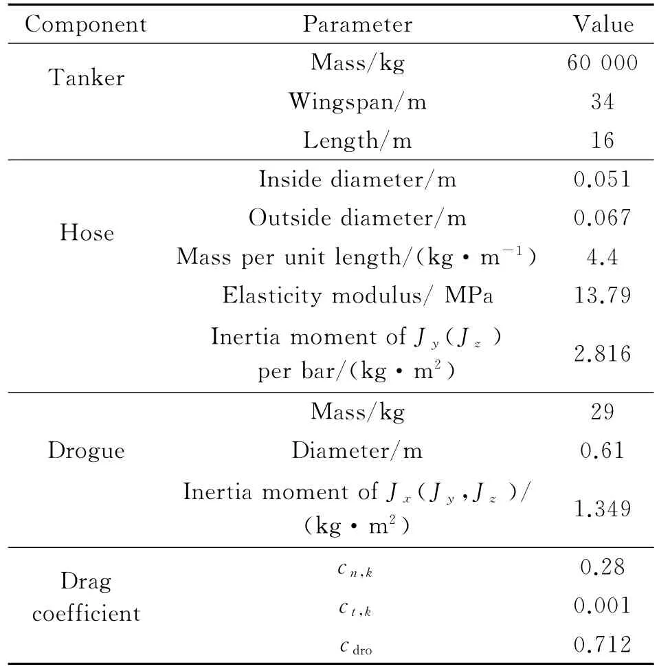
Table 1 The values of simulation parameters
In order to verify the correctness of the presented mathematical model,define drogue balance position asD=VD/LH,shown in Fig.1.The steady-state drag and balance position at various flight conditions is calculated as shown in Fig.3.
As Fig.3shows,the drogue drag and balance position are relative to the altitude and airspeed of the tanker.That is,the drogue distance(relative to the tanker)increases with the increasing tanker altitude,which is likely because the air density declines with increasing altitude and the drag of drogue decreases correspondingly.The steadystate position reduces while the tanker′s airspeed increases due to increased drag of drogue resulting from the speed up of tanker.
2.3.3 Dynamiccharacteristics
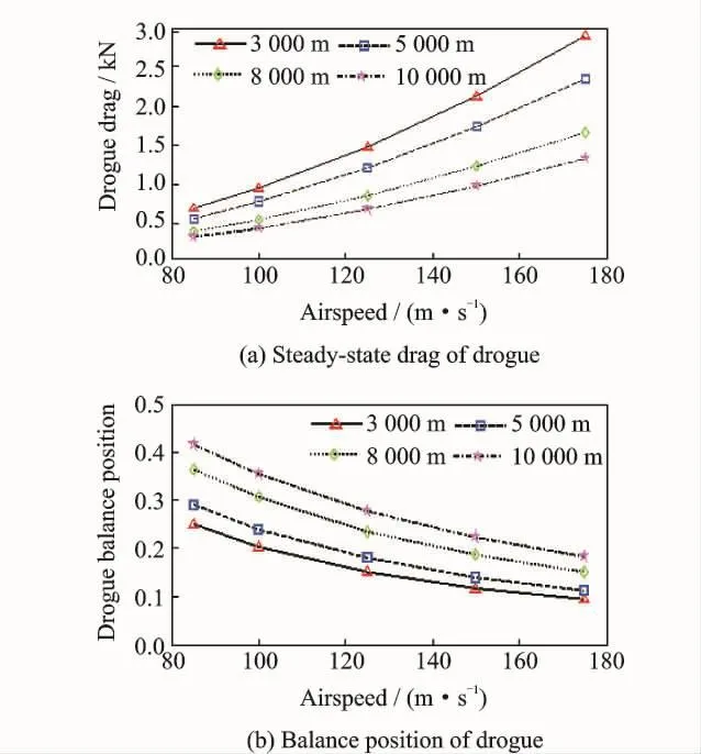
Fig.3 The steady-state drag and balance position in steady wind
As reported in flight tests,atmospheric turbulence had great influence on the dynamic per-formance of the hose-drogue system.Even on a clear day,the drogue swings in the air with slight disturbance,hardly finishing refueling task.In this paper,the problem is studied by incorporating the Dryden wind-turbulence model[24]into the hose-drogue model.Here,the turbulence generated is isotropic with the intensity of 1.5m/s and a length scale of 530m.The turbulence effects on the hose-drogue motion are shown in Fig.4.
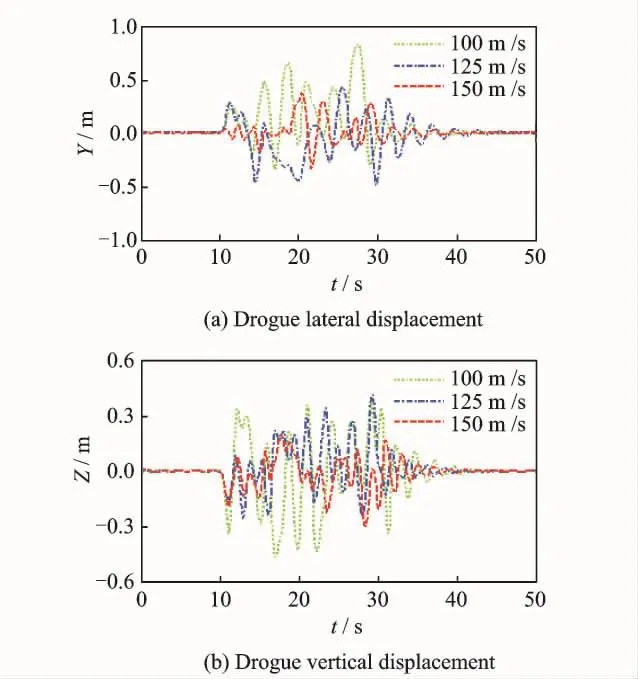
Fig.4 Drogue displacement in atmospheric turbulence at various speeds for a tanker at 8 000mheight
Fig.4shows the resulting responses,in which the system is suffered a 20sduration of turbulence air velocity starting att=10s.In Fig.4,as the tanker′s airspeed increases,the drogue′s displacement reduces.Since the speed of atmospheric turbulence remains still at fixed height,while the tanker′s airspeed is up,the relative rate of atmospheric turbulence′s speed with respect to tanker′s airspeed decreases.It appears that hose-drogue occurs irregular movement among the turbulence and it fails to settle to a steady-state position.It is consistently as described in the flight-test study.
3 Active Controller Design
Due to the influence by the atmospheric turbulence,the drogue moves in a continuous irregular pendulum way,which is difficult for receiver to dock accurately and safely.So it is essential to reduce the amplitude and frequency of drogue movement with active controller to improve the docking success rate.Here,a conceptual active control strategy by implementing aerodynamic control surfaces on the drogue for the hose-drogue system is investigated using the hose-drogue dynamic model.
3.1 Controller design model
The equations of motion for hose-drogue system derived in Section 2are in the form of 2nnonlinear 2nd order differential equations.It is necessary to convert them into a set of 1st order differential equations so as to be solved numerically.And the Runge-Kutta 4th order method with a fixed-step size is used for this work.Thus,the 4nstate variables of the set of angles and angular rates of the hose-bar orientation angles completely represent the current status.That is

Additionally,the input vectors are external load terms including the horizontal force and the vertical force which are operated by the active control device.That is

In the matter of output variables,the horizontal and vertical positions of the drogue are of interest,which may be defined along with the state and input vector as

In order to carry out control law design for the system,the model above need to be linearized at an equilibrium point.Thus,the control design model in state-space format is obtained by numerically linearizing at a reference equilibrium condition as follows
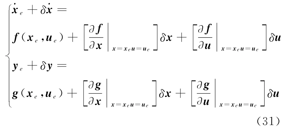
represented as

Since the order of the state-space model is too large to compute and needs to be reduced.A reduction model with 6th or even 2nd order system is obtained by applying the balanced model reduction technique.The step response of linearized models are shown in Fig.5.It is apparent that the lateral and the vertical motions of the drogue are decoupled from each other,thus a single-input-single output(SISO)design for each channel would be an option for active control design.The reduced order transfer functions of system are listed in Table 2.And the time domain behavior of full order and reduced order system are compared.It is without losing significant information in the system input-output behavior when the drogue moves less than 4.4rad/s[12].The pole-zero maps of the linearized models are shown in Fig.6.Fig.7 shows the frequency response,and Fig.8the unit step response of the full order and reduced order models.
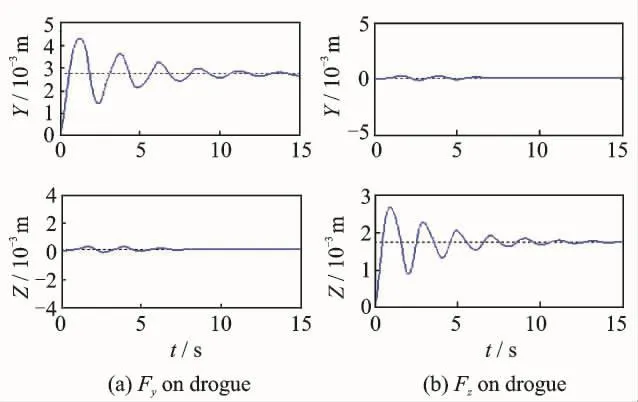
Fig.5 Step response of the linearized model

Table 2 The reduced transfer functions of the 6th order and the 2nd order
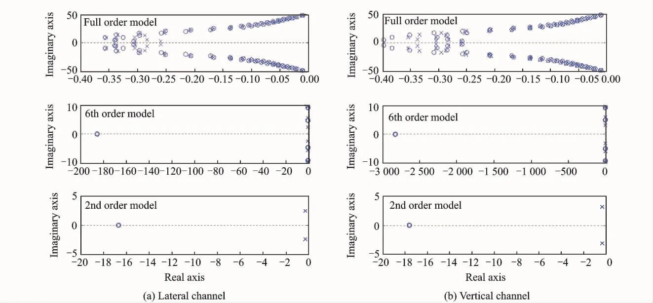
Fig.6 Pole-zero maps of the linearized models

Fig.7 Frequency response of the full-order vs reduced order models

Fig.8 Step response of the full-order vs.reduced order models
3.2 Regulator design
In order to devise a regulator that would maintain a relative stable position of drogue in the tanker wake and atmospheric turbulence,a control law is designed.A datum point is based on the natural steady-state position behind the tanker in the air,which is eithor set by the conclusion of steady-state characteristics analysis in Section 2.3 or estimated by mass of real flight tests and experiment datas.Assuming that the actual offsets of drogue position relative to the datum point can be measured.For instance,a differential global positioning system(DGPS)receiver or an electrooptical camera system on the drogue can be used.In order to keep the control design process simple,the 2nd order reduced model is chosen as the control design model.Furthermore,active controllers designed by proportion integral derivative(PID)and liner quadratic regulator(LQR)methods to compare the effectivities,respectively.The block diagram of the control simulation model is shown in Fig.9.

Fig.9 Control simulation model
3.2.1 PIDregulator
The conventional SISO design techniques are using for lateral and vertical channels,respectively.The transfer functions of PID controller are explained as follows

whereKPy=10 787.14,KIy=10 476.72,KDy=1 854.79,Ny=105.76,andKPz=10 603.98,KIz=10 671.05,KDz=1 509.66,Nz=79.37.
3.2.2 LQRregulator
A LQR is also designed to track relative position using the state-space model,where integrated signal of outputs are added to augment the model so as to reduce the steady-state error,that is=y.The augment model is as follows
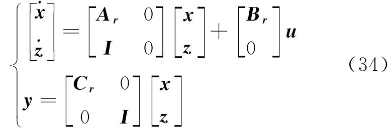
whereAr,Br,Crare the 2nd order state-space model matrix.And the conventional cost function is used


The closed-loop system of step input signal forPID and LQR controller are shown in Fig.10.
where the matrixQis a weight matrix relative to the error of state variablesx,whileRa weight matrix relative to the control effort.
According to the optimal control principle,the LQR controller is designed,and the gain matrixKis obtained by solving an algebraic Riccati equation as follows

whereQ=diag([12 000 8 000 8 000 10 000]),
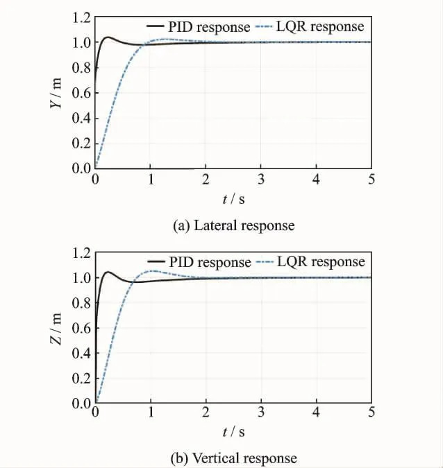
Fig.10 Closed-loop step response of the 2nd order PID& LQR control design model
The time response specifications for the hose-drogue system under consideration equipped with the proposed controllers are given in Table 3.

Table 3 Comparison of time response of PID and LQR
The simulation results,displayed in Fig.10 and Table 3,clearly show that both controllers are successfully designed and PID controller exhibits better transient performance.Then the same PID controller law is also acted on the 6th order as well as the full order linear model,the similar simulation results are obtained as shown in Fig.11.
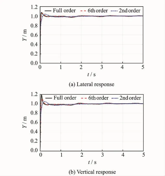
Fig.11 Closed-loop step response of PID controller acting on full-order vs reduced order models
3.3 Design evaluation
To further investigate the performance and validate the proposed controller,the control laws of PID and LQR are incorporated into the nonlinear model,respectively.The lateral and the vertical displacements of drogue are tested with and without the controller function,in which the system is suffered from the same turbulence air velocity as motioned in Section 2.As Fig.12shows,it is apparent that both PID controller and LQR controller greatly reduce the displacements.The maximum lateral and vertical displacements due to atmospheric turbulence reach 0.5—1mwith the controller powered off;while they are only 0.5—1cm with controller enabled.These results well coincide with the current design requirements of keeping drogue motion within 10cm.Besides,PID controller exhibits better control effect and higher control precision than LQR con-troller.From Figs.12(e)—(f),it is clear that the effect of both control laws are positive.The drogue position trajectory is irregular in the atmospheric turbulence without controller;while a fixed point is obtained with the controller enabled,which greatly improves the safety and accuracy of docking.As Fig.13shows,the maxium actuation force of the lateral and the vertical are 70Nand 40Nfor LQR controller,respectively;while they are 20Nand 30Nfor PID controller,respectively.These should be practically realizable forces with equipments.
4 Conclusions
A dynamic model of a hose-drogue for aerial refueling system based on Kane equation is developed using the finite-segment and lumped-mass approach,which does not require solution of the additional constraints equations for internal force.Numerical simulation results verify the correctness of the model,and simulations of hose-drogue position relative to the tanker under different flight conditions are conducted to testify the steady-state characteristic.The dynamic characteristic suffered from moderate-level atmospheric turbulence is also studied.The simulation results show the hose-drogue is unstable in air in turbulence.
Active controllers of PID and LQR are separately designed to stabilize the position of drogue by obtaining a linear model for the hose-drogue system at a reference fight condition.Also,both control laws are implemented into the orignal nonlinear model for a closed-loop simulation test with atmospheric turbulence,which show both controllers are of positive effect to reduce the oscillation amplitude of lateral and vertical motions of drogue.And by comparison,the PID controller exhibits better response and higher control precision.
In this paper,the influence of receiver bow wave,the design of control wing structure and related measurement sensors are not taken into account.Some of these works are currently under consideration and others are need to be further investigated in the future.
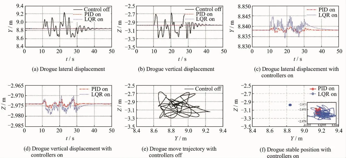
Fig.12 Active controller functionality in response to atmospheric turbulence(airspeed=150m/s,height=8 000m)

Fig.13 The control force of actuator for PID and LQR
Acknowledgements
This work was supported in part by the National Natural Science Foundation of China(No.61533008),the Fundamental Research Funds for the Central Universities(No.NZ2016104),and the Funding of Jiangsu Innovation Program for Graduate Education(No.KYLX15_0276).
[1] QUAN Q,WEI Z B,GAO J,et al.A survey on modeling and control problems for probe and drogue autonomous aerial refueling at docking stage[J].Acta Aeronautica et Astronautica Sinica,2014,35(9):2390-2410.(in Chinese)
[2] LU Y P,YANG C X,LIU Y Y.A survey of modeling and control technologies for aerial refueling system[J].Acta Aeronautica et Astronautica Sinica,2014,35(9):2375-2389.(in Chinese)
[3] RO K,KAMMAN J W.Modeling and simulation of hose-paradrogue aerial refueling systems[J].Journal of Guidance,Control,and Dynamics,2010,33(1):53-63.
[4] RO K,AHMAD H,KAMMAN J W.Dynamic modeling and simulation of hose-paradrogue assembly for mid-air operations[C]//AIAA Infotech@Aerospace Conference.[S.l.]:AIAA,2009.
[5] RO K,BASARAN E,KAMMAN J W.Aerodynamic characteristics of paradrogue assembly in an aerial refueling system[J].Journal of Aircraft,2007,44(3):963-970.
[6] HU M Q,NIE X,WANG L M.Detern ination of hose static catenary shape in″probe-drogue″in-flight refueling system[J].Journal of Air Force Engineering University(Natural Science Edition),2009,10(5):22-26.(in Chinese)
[7] HU M Q,LIU P,NIE X,et al.Influence of air turbulence on the movement of hose-drogue[J].Flight Dynamics,2010,28(5):20-23.(in Chinese)
[8] WANG H T,DONG X M,DOU H F,et al.Dynamic modeling and characteristics analysis of hoseparadrogue aerial refueling system[J].Jounal of Beijing University of Aeronautics and Astronautics,2014,40(1):92-98.(in Chinese)
[9] WEI Z B,QUAN Q,CAI K Y.Research on relationship between drogue position and interference force for probe-drogue aerial refueling system based on link-connected model[C]∥ Proceedings of the 31st Chinese Control Conference.Hefei,China:[s.n.],2012.(in Chinese)
[10]WEI Z B,DAI X H,QUAN Q,et al.Drogue dynamic model under bow wave effect in probe and drogue aerial refueling[J].IEEE Transactions on Aerospace and Electronic Systems,2016,52(4):1728-1742.
[11]DAI X H,WEI Z B,QUAN Q.Modeling and simulation of bow wave effect in probe and drogue aerial refueling[J].Chinese Journal of Aeronautics,2016,29(2):448-461.
[12]RO K,KUK T,KAMMAN J W.Active control of aerial refueling hose-drogue systems[C]∥ AIAA Guidance,Navigation,and Control Conference.Toronto,Ontario Canada:AIAA,2010.
[13]KUK T.Active control of aerial refueling drogue[D].Michigan:Western Michigan University,2014.
[14]RO K,KUK T,KAMMAN J W.Dynamics and control of hose-drogue refueling systems during coupling[J].Journal of Guidance Control & Dynamics,2011,34(6):1694-1708.
[15]WILLIAMSON W R,REED E,GLENN G J,et al.Controllable drogue for automated aerial refueling[J].Journal of Aircraft,2010,47(2):515-527.
[16]LIU Z,LIU J,HE W.Dynamic modeling and vibration control of a flexible aerial refueling hose[J].Aerospace Science & Technology,2016,55:92-102.
[17]WANG H T,DONG X M,XUE J P,et al.Dynamic modeling of a hose-drogue aerial refueling system and integral sliding mode backstepping control for the hose whipping phenomenon[J].Chinese Journal of Aeronautics,2014,27(4):930-946.
[18]WU L,SUN Y R,HUANG B,et al.Dynamic modeling and performance analysis of hose-drogue aerial refueling system[J].Journal of Nanjing University of Aeronautics & Astronautics,2016,48(6):901-908.(in Chinese)
[19]BOLENDER M A.Rigid multi-body equations-ofmotion for flapping wing MAVs using Kane′s equations[C]//AIAA Guidance,Navigation,and Control Conference.[S.l.]:AIAA,2009.
[20]YANG C X,YANG Y,LU Y P.Modeling and simula-tion for refueling boom and receiver in coupled model[J].Transactions of Nanjing University of Aeronautics and Astronautics,2017,34(2):143-151.
[21]WANG H T,DONG X M,LIU J L,et al.Dynamics and control of the hose whipping phenomenon in aerial refueling[C]// Aerospace Conference.[S.l.]:IEEE,2015:1-18.
[22]LI D W,WANG H L.Wake vortex effect modeling and simulation in automated aerial refueling[J].Jounal of Beijing University of Aeronautics and Astronautics,2010(7):776-780.(in Chinese)
[23]WEI Z Q,XU X H.Modeling and simulation of flow field for aircraft wake vortex[J].Journal of Transportation Systems Engineering and Information Technology,2010,10(4):186-191.(in Chinese)
[24]ZHAO Z Y,XIAO Y L,SHI Y.A digital simulation technique for Dryden atmospheric turbulence model[J].Acta Aeronautica et Astronautica Sinica,1986,7(5):433-443.(in Chinese)
杂志排行
Transactions of Nanjing University of Aeronautics and Astronautics的其它文章
- Numerical Study of Parachute-Payload Land Site Distribution with Randomize Wind Gust Model
- An Algorithm for Determination of Projectile Attitude Angles in Projectile Trajectory Prediction
- Perturbation Theory of Fractional Lagrangian System and Fractional Birkhoffian System
- Rotor Airload and Acoustics Prediction Based on CFD/CSD Coupling Method
- Aircraft Engine Gas Path Fault Diagnosis Based on Hybrid PSO-TWSVM
- Effect of Curing Age on Chloride Diffusion Coefficient of Recycled Aggregate Concrete Subjected to Compressive Stresses
