Rotor Airload and Acoustics Prediction Based on CFD/CSD Coupling Method
2018-05-25,,
, ,
National Key Laboratory of Science and Technology on Rotorcraft Aeromechanics,Nanjing University of Aeronautics and Astronautics,Nanjing 210016,P.R.China
0 Introduction
Helicopters present the unique capability to hover and fly at very low speeds to perform complex tasks.Rotor is the most important aerodynamic component of a helicopter,providing lift,propulsion and control[1].The capability of the rotor comes at the expense of significant noise.When a rotor operates in a low-speed forward or descent flight,tip vortices shed from the preceding blades move close to the following blades,which may lead to strong blade-vortex interaction(BVI)noise.BVI noise is the major source of annoyance[2].It is of great significance to study the unsteady aerodynamic loads and noise when the rotor is at a BVI condition.
Prescribed wake and free wake methods were used to calculate the induced velocities of rotor in previous studies,and the results were not satisfactory.With the rapid development of computer capability,rotor computational fluid dynamics(CFD)method with rigid blade assumption has gradually played an important role.The governing equations for solving flowfield evolve from transonic small disturbance (TSD)to Navier-Stokes(N-S)equations[3].Due to the complexity of CFD solution,blade structural deformation was not taken into account before mid-1980′s.Actually,when a helicopter rotor operates in forward flight,the aerodynamic loads on blade will be affected by its elastic deformation.In 1986,Tung et al.[4]first carried out CFD and CSD coupling research,and a TSD code was coupled with comprehensive analytical model of rotorcraft aerodynamics and dynamics (CAMRAD)by them.Pomin and Wagner calculated the airloads of the hovering Helishape 7Amodel rotor and a forward flight Caradonna-Tung(CTung)rotor[5].In their research,Timoshenko beam theory was adpoted in the CSD module,and the results showed better correlation with measured data than rigid blade computations about rotor thrust and torque coefficients.In 2008,Sitaraman et al.[6]predicted the rotor maneuver loads using CFD/CSD analysis.CFD and CSD solvers in their study were transonic unsteady rotor Navier-Strokes(TURNS)and DYMORE,respectively.Ref.[7]assessed the state-of-art of CFD/CSD codes using the HART II data.CFD/CSD method was also used for rotor aerodynamic noise prediction in recent years[8-9].
In the research of rotor aerodynamic noise,Williams and Hawkings derived the FW-H equation which governs the noise radiated from a solid body in arbitrary motion in Ref.[10].When the blade tip speed is subsonic,the contribution of quadrupole term to rotor noise is negligible,and the quadrupole term could be omitted in the righthand side of the FW-H equation.Thus monopole term and dipole term remain,which can be interpreted as thickness noise and loading noise source term.In the present investigation,the widely used F1Aformula derived from FW-H equation by Farassat[11]is adopted for noise analysis.
Domestic studies on this field are lag comparatively.Wang et al.[12-13]established CFD/CSD coupling method to calculate rotor airloads without involving rotor noise.Shi et al.[14]investigated the noise abatement level of advanced blade tip without considering blade elasticity.In order to understand the influence of blade deformation on rotor noise,this paper develops a new rotor aerodynamic noise prediction method by combining CFD/CSD coupling model with the F1Aformula.The UH-60Ahelicopter is taken as a numerical example,and the computations of flowfield and noise are performed in a low-speed for-ward flight.A structured moving overset grid system is generated and the CFD solution is based on Reynolds-Averaged Navier-Stokes(RANS)equations.The CSD solution is based on Euler-Bernoulli beam model and Hamilton′s variational principle.The elastic deformation of the blade grid is achieved by an algebraic method.Besides,the airloads and structural deformations between CFD and CSD module are transferred via interpolation.The results indicate that the normal force coefficients calculated by CFD/CSD are more accurate than that by isolated CFD method,and their difference of noise level can be up to 5dB at some observer positions.
1 Numerical Methods

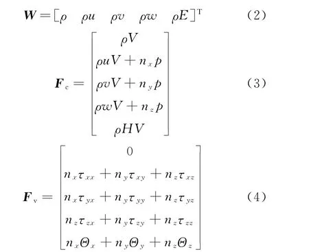
whereΩis the control volume,Wthe conservative variables,FcandFvthe convective and the viscous fluxes,respectively.Their expressions are as follows
1.1 Rotor CFD model
N-S equations for three-dimensional unsteady compressible flows in conservative form are given by[15]
The spatial discretization of the governing equations is achieved by Jameson central scheme.The dual time-stepping approach is implemented,and explicit Runge-Kutta method is employed at each pseudo time step.The turbulence model adopted in the present analysis is Baldwin-Lomax model.In order to improve the calculation efficiency,the background Cartesian grid is divided into several blocks and the MPI parallel strategy is used.
1.2 Rotor CSD model
Blade structural model is decoupled into two parts:A nonlinear one-dimensional beam model and a linear two-dimensional cross-section model.The blade dynamics model is shown in Fig.1.

Fig.1 Schematic of blade dynamics model
Each beam element includes two end nodes and one internal node at its midpoint.The end node has 6degrees of freedom (DOFs):Axial displacementu1/u2,transverse deflectionsv1/v2,w1/w2and their radial derivativesv′1/v′2,w′1/w′2,and torsional elastic deformation1/2,while the internal node has only two DOFs (3 andu3).
Finite element modeling of the beam is based on Hamilton principle[16]

whereUis the strain energy,Tthe kinematic energy andWethe work of external loads,which are aerodynamic forces and moments of the blade in this analysis.
The strain energy,kinematic energy and work of external loads on theith element can be derived from its degrees of freedom.The generalized displacements can be assumed as

wherev,w,,uare generalized displacements at any point on the beam element;Φv,Φw,ΦandΦuspace-dependent interpolation functions;V,W,ΦandUtime-dependent nodal parameters of each generalized displacement.Hermite interpolation polynomials are employed in space-dependent interpolation functions.
The finite-element equations of motion for theith element are given by

whereMiis the mass matrix,Cithe damping matrix,Kithe stiffness matrix,andFithe load vector.All the motion equations of each element are assembled and the nodal generalized displacement vectorqcan be solved.More details on CSD model can be found in Ref.[16].
1.3 Rotor aerodynamic noise model
Rotor noise includes thickness noise,loading noise and quadrupole noise.When the blade tip speed is subsonic,the quadrupole noise is negligible.Based on F1Aformula,rotor noise calculation is defined as

wherep′(x,t)is the total acoustic pressure,andp′T(x,t)andp′L(x,t)on the right hand side are thickness and loading noise pressure,respectively.Their expressions can be written as[17]
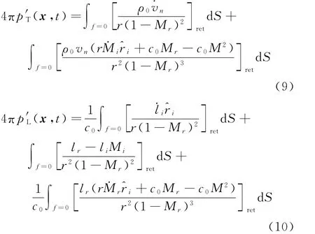
where the subscript ret denotes the retarded time.The terms appearing on the right of Eqs.(9),(10)are only related to surface integral and can be solved numerically using the airloads on the blade surface.
1.4 Flowchart of noise calculation based on CFD/CSD coupling method
The rigid body displacements of the blade can be easily obtained by Euler transformation.Besides,an efficient algebraic gird deformation method[18]is used to get blade elastic displacements.The deformation at arbitrary location on the blade can be defined as a function of radius and azimuth at the quarter chord and at any section,a rotation matrixTand a vectorxlinare used to get the deformed grid coordinates

wherex,yandzare the grid coordinates before deformation.
Fig.2is the flowchart of noise calculation based on CFD/CSD coupling method.The detailed procedures are as follows.
(1)Generate a moving overset grid system around the rotor;
(2)For the prescribed flight parameters and blade structural parameters,initialize the CSD module with a simple aerodynamic model;
(3)When the CSD solution is finished,the deformations of the blade are transferred to the CFD module;
(4)CFD time-marches at each azimuth (0.5 degrees per timestep);
(5)If the azimuth equals 360/Nb(Nb is the number of blades),the airloads are transferred to the CSD module.
Repeat steps (3—5)until the flowfield is converged.After that,rotor noise is calculated by F1Aformula and the iteration is completed.
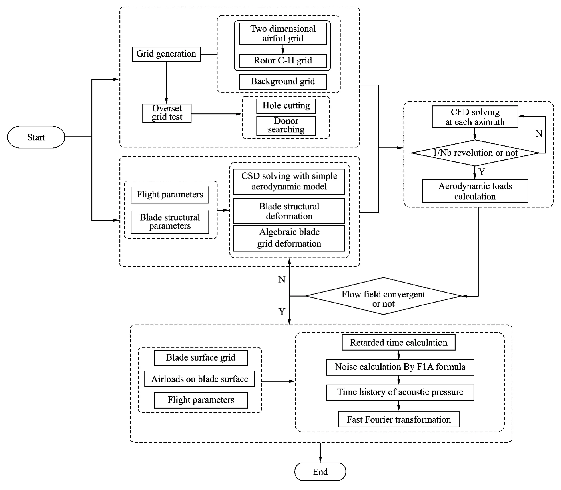
Fig.2 Flowchart of noise prediction based on CFD/CSD coupling method
2 Validations of Numerical Methods
2.1 Validation of rotor CFD model
In order to verify the CFD model,the hovering UH-60Arotor case is presented firstly and the blade model is rigid in this section.The UH-60Ais a four-bladed helicopter with advanced blade shape (multiple airfoils,variational chord and irregular twist)[19].Blade tip Mach number and collective pitch of the case areMatip=0.628 andθ0.75=9°.The blade grid follows a C-H topology.198points are used in the wrap around direction,44points in the normal direction,and 98 points in the spanwise direction.The schematic of the blade grid is given in Fig.3.The background grid is Cartesian grid.

Fig.3 Blade CFD grid used in simulations
The predicted blade pressure coefficientsCpfrom the CFD analysis are compared with test data in Ref.[20].Two representative span stations are shown in Fig.4.
From Fig.4,it can be seen that the calculatedCpagrees favorably with the test data.The accuracy of the CFD model in this analysis is validated.
2.2 Validation of rotor CSD model
Nondimensional natural frequencies of the model rotor in Ref.[16]are calculated.The model rotor blade is isotropic,hingeless,and soft-inplane.Frequency comparisons for the blade are summarized in Table 1.A blade-tip deflection analysis atμ=0.3is also conducted,and the comparisons with Ref.[16]are depicted in Fig.5.It needs to be noted that in order to validate the CSD model solely,aquasi-steady aerodynamic model is adopted in this section.

Fig.4 Blade pressure coefficient of UH-60Ain hover

Table 1 Natural frequencies of model rotor blade
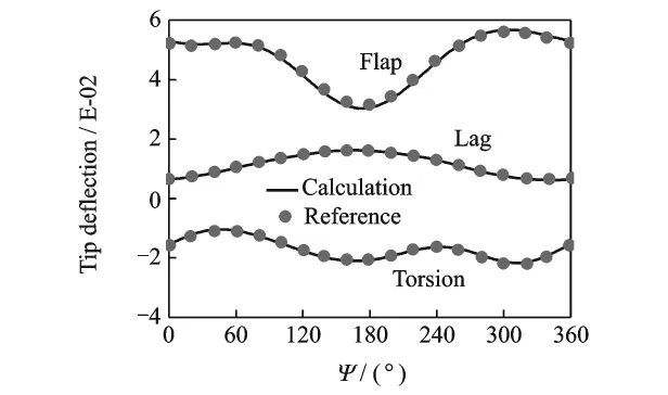
Fig.5 Nondimensional blade-tip deflections of model rotor
As seen in Table 1and Fig.5,the calculated blade natural frequencies and tip deflections are highly correlated with the results in Ref.[16].The availability of the CSD model is validated.
2.3 Validation of rotor noise model
The acoustic pressure time history result of 1/4scale UH-1model rotor atμ=0.2was compared with the data in Ref.[17].The radius of this two-blade model rotor is 1.829mand with a backward rotor shaft angleαS=8.8°,and the coordinate of observation point is(3.21,-2.16,-0.3)m.As can be seen from Fig.6,the acoustic pressure result of this paper has a favorable correlation with reference data.
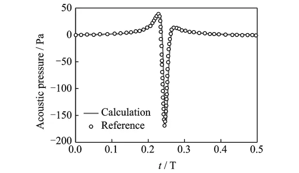
Fig.6 Acoustic pressure of UH-1model rotor
3 Airload and Noise Analysis Based on CFD/CSD Coupling
3.1 Rotor airload prediction based on CFD/CSD coupling
Airloads of flight test Counter C8513of UH-60Aisolated rotor in Ref.[21]are investigated to demonstrate the accuracy and robustness of CFD/CSD coupling model in this paper.C8513is a lowspeed level flight state.The flight parameters and trimmed control angles are documented in Table 2,and the azimuthal step size of CFD and CSD are 0.5°and 2°,respectively.
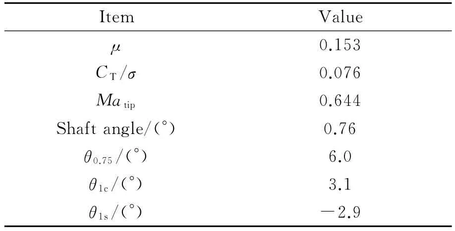
Table 2 Flight parameters of counter C8513
The elastic blade flap and torsion are considered very important to get correct prediction of airload.Since the effective angle of attack of each blade section is directly related to flap and torsion variation.In Fig.7,the elastic blade tip deflection results in flap and torsion of CFD/CSD coupling method are demonstrated.The coupling frequency between CFD and CSD is 90°and the solution has converged after 4rotations of computation.As can be seen from the converged deflection curve,the mean elastic blade tip flap and torsion deflection of one rotation period are about 6%Rand -2°,respectively.Due to the high aspect ratio of UH-60Arotor blade,which approximately equals to 15.5,the influences of elastic blade flap and torsion on airload are significant even at a relative low advance ratio.
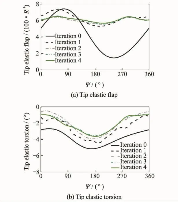
Fig.7 UH-60Ablade tip elastic flap and torsion
Fig.8shows the vorticity iso-surfaces around the rotor based on CFD/CSD coupling.There are noticeable blade-vortex interactions at advancing and retreating side.Normal force coefficient comparisons with flight test data[21]at three different sections are given in Fig.9.Present isolated CFD method also calculates 4rotations to obtain converged airload results.It can be seen that the rapid changes in blade airloads near 90°and 270°azimuths are captured for both the CFD method and the CFD/CSD coupling one,but the results from CFD method is overpredicted and less satisfactory than CFD/CSD method at the two outer sections.This can be mainly attributed to the inclusion of flapwise and torsional elastic deflection in CFD/CSD coupling method.It is shown that the airloads calculated by CFD/CSD coupling method can be employed in the noise calculation.

Fig.8 Vorticity iso-surfaces for UH-60Arotor
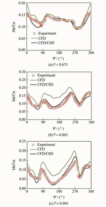
Fig.9 Normal force coefficient for UH-60Arotor
3.2 Rotor noise prediction based on CFD/CSD coupling
One commonly used way to demonstrate the noise radiated from the rotor is to display the magnitude and directivity on the surface of a noise hemisphere[22].Fig.10shows a typical noise hemisphere.The hemisphere is mapped to 2Dplane by Lambert Conformal Conic projection and in this way one can get an intuitive understanding of noise radiation pattern.
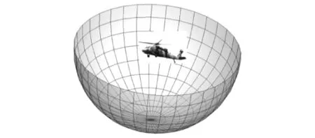
Fig.10 Schematic of typical noise hemisphere
The noise hemisphere of flight test Counter C8513of UH-60Ais shown in Fig.11.Robsis the radius of noise hemisphere and letRobs=3Rin present analysis.The hemisphere is spread out along the 0°azimuth.The right side of the figure is the advancing side and the top of the projection is in front of the rotor.The center of the projection corresponds to the bottom of the hemisphere.Figs.11 (a,b)represent thickness noise and loading noise distributions calculated by CFD/CSD method,respectively.Fig.11 (c)is the difference of loading noise between CFD/CSD and CFD.It is needed to be noted that the effect of blade elastic deformation on thickness noise is negligible,thus the thickness noise calculated by isolated CFD method is not plotted.
It can be seen from Fig.11 (a)that,in the rotor tip-path plane,thickness noise levels(above 95dB)at 180°azimuth is higher than that at 0°and this phenomenon is caused by the Doppler effect.In addition,the noise level at the bottom of the rotor is much less than that in the rotor tippath plane(below 40dB).Therefore,the propagation of thickness noise is along the rotor tippath plane.
As seen in Fig.11 (b),when rotor operates in a BVI state and the transonic effect of blade tip is not significant,the loading noise is much higher than thickness noise and is the dominant source(above 100dB at most observer positions).In contrast with thickness noise,the″hotspot″of loading noise is approximately underneath the advancing side of the rotor.

Fig.11 Schematic of noise projection,Robs=3R
Fig.11(c)shows that,for most observer positions on the hemisphere,there are only minor differences between the magnitudes of loading noise calculated by CFD/CSD and CFD.However,at some observer locations the difference of loading noise level can be up to 5dB.This can be attributed to the different airloads calculated by the two methods.Thus a high fidelity in airloads prediction is necessary for accurate noise analysis.
The time and frequency domain results of peak thickness and loading noise are shown in Fig.12and Fig.13,respectively.The noise spectrum is obtained by a Fourier analysis of acoustic pressure.Fig.12 (a)demonstrates that thickness noise is characterized by periodic and negative pulses.Fig.12(b)illustrates that the amplitude decreases rapidly with increasing harmonic number.As a contrast,the time history of loading noise in Fig.13(a)is not as smooth as Fig.12(a)and this is caused by the unsteady airloads.Besides,the harmonics fall off more slowly in Fig.13(b)than Fig.12(b).

Fig.12 Acoustic pressure and spectrum of peak thickness noise
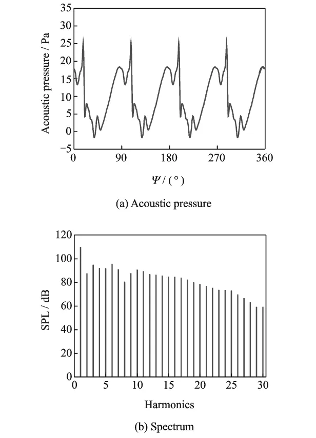
Fig.13 Acoustic pressure and spectrum of peak loading noise
4 Conclusions
A noise prediction method is developed with an implementation of CFD/CSD coupling.A lowspeed forward flight case of UH-60Arotor is calculated and the airloads are used for rotor noise analysis.The following conclusions can be drawn from results presented:
(1)When the structural elasticity is taken into account,the difference of loading noise levels calculated by CFD/CSD and CFD can be up to 5 dB at some observer positions.
(2)For the low-speed forward flight state(μ=0.153)investigated in this paper,there are blade-vortex interactions near 90°and 270°azimuths,which results in rapid fluctuations in blade airloads.
(3)The blade-vortex interactions are captured by both CFD/CSD method and isolated CFD method at three different sections calculated.However,the airloads predicted by isolated CFD method are less satisfactory than CFD/CSD coupling method.
(4)Loading noise level is much higher than thickness noise when rotor operates in a low tip Mach number and at a BVI condition,and it becomes the dominant contributor to rotor noise.
(5)A CFD/CSD coupling method for noise analysis is developed in this paper.Numerical examples show that the method is robust in flowfield simulation and noise prediction of rotors.
Acknowledgement
This work was supported by Funding of Jiangsu Innovation Program for Graduate Education(No.KYLX16_0389).
[1] JOHNSON W.Helicopter theory[M].New York,USA:Dover Publications,1994:10-11.
[2] HUBBARD H H.Aeroacoustics of flight vehicles:Theory and practice NASA-AD-A241141[R].Hampton USA:National Aeronautics and Space Administration,1991:102-105.
[3] CONLISK A T.Modern helicopter rotor aerodynamics[J].Progress in Aerospace Sciences,2001,37(5):419-476.
[4] TUNG C,CARADONNA F X,JOHNSON W R.The prediction of transonic flows on an advancing rotor[J].Journal of the American Helicopter Society,1986,31(3):4-9.
[5] POMIN H,WAGNER S.Navier-Stokes analysis of helicopter rotor aerodynamics in hover and forward flight[J].Journal of Aircraft,2002,39(5):813-821.
[6] SITARAMAN J,ROGET B.Prediction of helicopter maneuver loads using a coupled CFD/CSD analysis[C]//26th International Congress of the Aeronautical Sciences.Anchorage,Alaska,USA:The ICAS International Inc,2008:1-26.
[7] SMITH M J,LIM J W,van der Wall B G,et al.An assessment of CFD/CSD prediction state-of-the-art using the HART II international workshop data[C]//American Helicopter Society 68th Annual Forum.Fort Worth,USA:The AHS International Inc,2012:1-41.
[8] BOYD D D.HART-II acoustic predictions using a coupled CFD/CSD method[C]//American Helicopter Society 65th Annual Forum.Grapevine,Texas,USA:The AHS Inernational Inc,2009:1-19.
[9] LIM J W,STRAWN R C.Prediction of HART II rotor BVI loading and wake system using CFD/CSD loose coupling [C]//Proceedings of the 45th AIAA Aerospace Sciences Meeting and Exhibit.Reno,Nevada,USA:AIAA,2007:1-15.
[10]WILLIAMS J E F,HAWKINGS D L.Sound generation by turbulence and surfaces in arbitrary motion[J].Philosophical Transactions of the Royal Society of London A:Mathematical,Physical and Engineering Sciences,1969,264(1151):321-342.
[11]FARASSAT F.Derivation of formulations 1and 1A of Farassat:NASA-TM-214853[R].Hampton,Virginia,USA:National Aeronautics and Space Administration,2007:1-25.
[12]WANG Junyi,ZHAO Qijun,XIAO Yu.Calculations on aeroelastic loads of rotor with advanced blade-tip based on CFD/CSD coupling method[J].Acta Aero-nautica et Astronautica Sinica,2014,35(9):2426-2437.(in Chinese)
[13]XIAO Yu,XU Guohua,SHI Yongjie.Aeroelastic analysis of helicopter rotors using computational fluid dynamics/comprehensive analysis loose coupling model[J].Proceedings of the Institution of Mechanical Engineers Part G Journal of Aerospace Engineering,2014,229(4):621-630.
[14]SHI Yongjie,SU Dacheng,XU Guohua.Research on influence of shape parameters on blade-vortex interaction noise of helicopter rotor[J].Journal of Nanjing University of Aeronautics and Astronautics,2015,47(2):235-242.(in Chinese)
[15]BLAZEK J.Computational fluid dynamics:Principles and applications[M].Kidlington,Oxford,UK:Elsevier,2005:16-17.
[16]YUAN K A,FRIEDMANN P P.Aeroelasticity and structural optimization of composite helicopter rotor blades with swept tips:NASA-CR-4665[R].Hampton,Virginia,USA:National Aeronautics and Space Administration,1995:106-107.
[17]BRENTNER K S.Prediction of helicopter rotor discrete frequency noise:A computer program incorporating realistic blade motions and advanced acoustic formulation:NASA-TM-87721[R].Hampton Virginia,USA:National Aeronautics and space Administration,1986:1-93.
[18]DATTA A,SITARAMAN J,CHOPRA I,et al.CFD/CSD prediction of rotor vibratory loads in highspeed flight[J].Journal of Aircraft,2006,43(6):1698-1709.
[19]BOUSMAN W G.Aerodynamic characteristics of SC1095and SC1094R8airfoils:NASA-TP-212265[R].Moffett Field,California,USA:National Aeronautics and Space Administration,2003:1-50.
[20]LORBER P,STAUTER R,Landgrebe A.A compre-hensive hover test of the airloads and airflow of an extensively instrumented model helicopter rotor[C]//American Helicopter Society 45th Annual Forum.Boston,MA,USA:The AHS International Inc,1989:1-16.
[21]POTSDAM M,YEO H,JOHNSON W.Rotor airloads prediction using loose aerodynamic/structural coupling[J].Journal of Aircraft,2006,43(3):732-742.
[22]GREENWOOD E.A physics-based approach to characterizing helicopter external noise radiation from groundbased noise measurements[D].Maryland:Univ of Maryland,2008.
杂志排行
Transactions of Nanjing University of Aeronautics and Astronautics的其它文章
- Numerical Study of Parachute-Payload Land Site Distribution with Randomize Wind Gust Model
- Modeling Method and Control Strategy for Hose-Drogue Aerial Refueling System
- An Algorithm for Determination of Projectile Attitude Angles in Projectile Trajectory Prediction
- Perturbation Theory of Fractional Lagrangian System and Fractional Birkhoffian System
- Aircraft Engine Gas Path Fault Diagnosis Based on Hybrid PSO-TWSVM
- Effect of Curing Age on Chloride Diffusion Coefficient of Recycled Aggregate Concrete Subjected to Compressive Stresses
