球床模块式高温气冷堆中的炭材料
2018-05-02周湘文卢振明唐亚平
周湘文, 杨 杨, 宋 晶, 卢振明, 张 杰, 刘 兵, 唐亚平
(清华大学 核能与新能源技术研究院, 先进核能技术协同创新中心, 先进反应堆工程与安全教育部重点实验室, 北京100084)
1 Introduction
Carbon is one of the abundant elements on the earth. Almost all organics are composed of carbon networks, and carbon materials are very familiar in our daily lives, for example, ink for newspapers, “lead” for pencils, carbon fibers for reinforcement of rackets and fishing rods, etc. Carbon materials, consisting mainly of carbon atoms, have been used since the prehistoric age as charcoal for heating and cooking. In ancient times, people began to use carbon materials for copper and iron smelting. In the beginning of 19thcentury, carbon materials began to be used as electrodes for batteries. In 1880s, large-sized carbon rods that were industrially produced by heat treatment at high temperatures, as high as 3 000 ℃, were used as electrodes for steel refining. These carbon rods were called graphite electrodes because the crystalline graphite structure was well developed in most of them[1]. From then on, various carbon materials having a graphite structure or without a noticeable graphite structure were developed and opened new applications. In general, carbon materials are closely related to the human’s industrial production and daily life.
Compared with the long history of human’s use of carbon materials, the debut of carbon materials in nuclear reactors took place only 75 years ago. In 1942, the first nuclear pile, designated Chicago Pile 1 (CP-1), was constructed on a squash court at the University of Chicago, which contained ~385.5 tons of graphite, the vast majority being grade AGOT manufactured by the National Carbon Company[2]. When a group of scientists led by Enrico Fermi attempted to produce a self-sustaining nuclear chain reaction, graphite was chosen as the moderator because it was the only suitable material available. CP-1 produced the world’s first nuclear chain reaction on December 2, 1942 and operated at a low power of about 0.5 watt for several days. The pile was then disassembled and rebuilt at what is now the site of Argonne National Laboratory, USA.
2 Why choose carbon materials(graphite)
Nuclear fission of isotopes such as92U233,92U235, and94Pu239is the main process generating nuclear energy in nuclear reactors. The fission of a heavy element is usually initiated by an impinging neutron with release of energy and further neutrons. Although an integral number of neutrons is emitted for any one fission, the average yield per fission is about 2.5 neutrons with the energy of a mean value of about 2 MeV. The possibility that fission or any other neutron-induced reaction will occur is described by the neutron cross-section for that reaction. As shown in Fig. 1, the fission cross-section of92U235and94Pu239increases as neutron velocity decreases, i.e., the longer a neutron dwells near nucleus as it passes, the more probable it is that it will react with that nucleus. Therefore, it is advantageous in the operation of a nuclear fission reactor to slow the fission neutrons (fast neutrons) to neutrons with lower energies (~0.025 eV at RT, thermal neutrons). The slowing down process is termed “moderation”. In a thermal reactor, the fast neutrons produced by fission are slowed down in a non-absorbing medium called a “moderator”.

Fig. 1 Fission cross-section of uranium and plutonium with the fission neutron energy [3].
A good moderator must efficiently slow down the fast neutrons by neutron-nucleus elastic collisions. According to the fundamental consideration of Newton’s law, it is obvious that the candidate moderators are based on elements of low atomic weight. Practically, this limits the choice to elements of atomic number less than sixteen. The chance of neutron captured by moderator impurities or absorbed by reactor structural materials is thus reduced. In common, when assigning orders of merit to moderators, moderating ratio is always used, which accounts for the average energy loss per collision, and the scattering and neutron adsorption cross-sections of a moderator[4-6]. A complete picture of moderator nuclear performance should take the density of the moderator into consideration. For example, gases are of little use as moderators because of their low density. According to the requirements of a good moderator mentioned above, the choice of candidate moderators thus limits to the four materials shown in Table 1.
Table 1 Moderating ratios and densities of candidate moderators[5].
The candidate materials listed in Table 1 are either liquid or solid, which present acceptable density properties. Ordinary water is pretty easy to get with low cost and unaffected by neutron irradiation. However, neutron adsorption by hydrogen in H2O decreases its moderating ratio. Although the heavy water (D2O) has the highest moderating ratio, the cost to separate the D2O from H2O is considerably high and D2O is likely to leak out, which make the D2O as the first choice for the moderator impossible. Beryllium is a good moderator, but it suffers from the disadvantages that it is expensive, hard to machine, and highly toxic. Eventually, carbon was first chosen as an acceptable moderator used extensively in the form of graphite, which offers an acceptable compromise between nuclear properties, cost and utility[5-7]. It has a reasonably high moderating ratio as well as good structural strength, and it can be easily machined into the complex shapes required to form graphite cores. Thermally, graphite has a high thermal conductivity, low coefficient of thermal expansion and very high sublimation temperature, ~4 000 K, so it will not exhibit phase change. Graphite is not susceptible to thermal shock and in the event of a loss of coolant accident the mass of a graphite core acts as a thermal sink extending thermal transient times to many hours in length, giving ample time for safety-related remedial actions to take place. However, the use of graphite as a moderator and structural material in reactors is not perfect. The significant effects of neutron irradiation on the structure and properties of graphite must be taken into consideration[5].
3 History and development of HTRs
3.1 History of nuclear reactors
After the first nuclear reactor CP-1 had been built in 1942, the nuclear energy technologies began to enter a period of rapid development. The first grid-connected commercial nuclear power plant (APS-1 Obninsk) was accomplished in 1954 in Soviet Union. After six decades of development, there are 447 operable civil nuclear power reactors around the world, with a further 61 under construction. Most of the nuclear reactors belong to the Generation II or III nuclear reactors. In 2014, the world’s nuclear reactors supplied 2441 TWh of electricity (2441 billion kilowatt hours), which represents around 10% of global electricity consumption[8]. When we enjoyed the unprecedented enormous merits that the development of nuclear power had brought, its security problem cannot be ignored by international society. The nuclear accidents such as the Three Mile Island accident (1979), Chernobyl disaster (1986) and the Fukushima Daiichi nuclear disaster (2011) brought challenges to the safe utilization of nuclear power. In 2002, ten countries joined together to form Generation IV International Forum (GIF) to develop future-generation nuclear energy systems that can be licensed, constructed, and operated in a manner that will provide competitively priced and reliable energy products while satisfactorily addressing nuclear safety, waste, proliferation, and public perception concerns[9]. Six nuclear power reactor systems were selected to Generation IV by the GIF. The six Generation IV systems presented four main characteristics including highly economical, enhanced safety, minimal waste, and proliferation resistant. Along with the use of carbon-coated uranium oxide fuel particles[10], the use of graphite as a moderator for Generation IV reactors is attractive because it allows a reactor core to be designed in a way which, in fault conditions, can reach high enough temperatures to allow the "Doppler effect”[11]to come into play which will shut down the reactor. Such a design does not require operator actions or electronic feedback to safely shut down the reactor in the event of a loss of coolant incident and can be considered to be passively nuclear safe. The two main Generation IV graphite moderated designs include the very/high temperature gas-cooled reactors (VHTR or HTR) and the molten salt-cooled reactor (MSR). Among the six reactor systems, the V/HTR is generally believed to be the most promising advanced reactor to achieve the commercialization[12].
3.2 Development of HTGs
Gas cooled reactors (GCRs) were the initiator for the HTRs. Development of HTRs began in 1950s to improve upon the performance of GCRs. Dragon with 20 MWth was the first HTR in the world which first operated in UK in 1965. The primary objective of Dragon was to demonstrate the feasibility of HTR. Since then, the HTRs such as Arbeitsgemeinshaft Versuchsreaktor (AVR) with 15 MWe and Peach Bottom with 40 MWe started operation in Germany and USA in 1967, respectively[13]. After a break due to the nuclear phaseout in Germany and USA, HTR development restarted during last decade with new industrial demonstration projects in the US (NGNP), Japan (GTHTR-3000), Korea (NHDD) and Russian (GT-MHR). The renewed worldwide interest for HTR and for its advanced version for higher performances in terms of temperature and fuel burn-up, VHTR, has indeed been driven by their attractive safety based on specific inherent behavior (large thermal inertia, strongly negative temperature coefficient, high temperature resistance of the fuel, chemical inertia of the coolant, etc.)[14]. In China, a 10 MWthHigh Temperature Gas-cooled Reactor-test module (HTR-10) whose construction commenced in 1995, reached its first criticality in the end of 2000 and full power in 2003[15]. Based on the experiences of HTR-10, a 2×250 MWthHigh Temperature gas-cooled Reactor Pebble-bed Module (HTR-PM) with inherent safety started its construction in 2012 in Shidao Bay, Rongcheng City of Shandong Province[16]. Currently, HTR-PM is the only modular HTR demonstration plant being built, which indicates that China’s HTR technology is in the leading position in the world. Moreover, we have fully proprietary intellectual property rights of HTR-PM. The leading position and proprietary intellectual property rights of HTR-PM are very crucial for China to seize the world nuclear power peak and move from a nuclear power country with huge industrial scale to a stronger one.

Fig. 2 Schematic for the application of carbon materials in HTR-PM.
4 Carbon materials in HTR-PM
HTGR designs use helium as the coolant gas, ceramic TRISO-coated particles as the fuel, and carbon materials as the structural materials and matrix materials for fuel elements. Past designs represent two primary core concepts commercially favored for HTRs: the prismatic block reactor (PMR) and the pebble-bed reactor (PBR)[17]. Both of the HTR-10 and HTR-PM in China are PBRs. Five types of carbon materials including the structural graphite, matrix graphite (MG) and coating carbon layers for spherical fuel elements, fuel-free graphite pebbles and carbon blocks are used in the HTR-PM. As shown in Fig. 2, there is a cylinder reactor core in the center of HTR-PM with an equivalent diameter of 3 m and equivalent height of 11.8 m. The fuel-free graphite pebbles and spherical fuel elements of which more than 90% is consisted of MG are piled loosely in the reactor core. The reactor core does not contain any fuel-free region or a graphite reflector in the center. The inner structural graphite reflector and outer carbon blocks surrounding the reactor core forms a ceramic cylinder structure with an outer diameter of 5 m and a total height of 16.8 m. The components of structural graphite and carbon block vary in shape, which have a total number of more than 3 000, with more than 200 types. The total weight of structural graphite and carbon block components (CBC) is about 1 000 tons. On the outside of the ceramic material structure is the metal components and reactor pressure vessel.
4.1 Structural graphite components
The structural graphite components play many important roles such as the neutron reflector and moderator in guaranteeing the operation and integrity of HTR-PM. As shown in Fig. 2, the structural graphite components mainly consist of the side reflector, top reflector and bottom reflector. Each component uses tenons, keys, pins, casing pipes and other connections to guarantee the core integrity of HTR-PM. The maximum dimension of a single structural graphite component is 1.9 m in length, 0.7 m in width, and 0.4 m in height. The functions of structural graphite components in HTR-PM are shown in the respects as follows:
(1)Forming the pebble-bed reactor core and flow channels for spherical fuel elements and helium coolant;
(2)Providing the guide channels for control rods and adsorption balls shutdown system;
(3)Acting as the neutron reflector, and thermal and neutron’s shielding components;
(4)Ensuring the integrity of components in the reactor.
During the service period of structural graphite, high temperature and high irradiation doses in the reactor make the structural graphite bear a variety of impacts and stresses as shown below:
(1)Gravity load produced by the itself-weight of graphite and the components on the graphite;
(2)Stresses induced by the pressure difference in the flow of helium gas;
(3)Stresses generated by seismic oscillation;
(4)Thermal stresses produced by the steady and transient temperature field;
(5)Property degradation induced by oxidation corrosion during the air or moisture ingression accidents;
(6)Irradiation deformation and damage induced by the irradiation of fast neutrons.
Table 2 Typical property requirements of nuclear-grade structural graphite for HTR-PM.
During the whole lifetime of HTR-PM as a PBR, the core support structural graphite is commonly considered permanent. To a certain extent, the life span of the nuclear structural graphite determines the lifetime of the HTR-PM. Characteristics required for modern nuclear graphite used in HTRs as structural graphite are: (1) high purity with a low elemental contamination (especially Boron); (2) acceptable isotropic or near isotropic property; (3) machinability into large graphite components; (4) validated irradiation database. While these are fundamental and necessary attributes to obtain acceptable lifetime of structural graphite components within a HTR irradiation environment, they may not be sufficient to demonstrate adequate structural integrity for all design configurations. Typical property requirements of structural graphite for HTR-PM are presented in Table 2. The property variations within a billet due to forming and thermal processes, and statistical variations in properties between billet to billet within a batch, and among production batches because of variations in raw materials, formulations and processing conditions must be taken into consideration. Taking the tensile strength as an example, if the tensile strength of the graphite accords to the normal distribution, the average (μ) and corresponding standard deviation (σ), and the ratio ofσto μ (σ/μ) are needed. If the tensile strength of the graphite follows the 2-parameter Weibull distribution, the shape and dimension parameters of the graphite must be given. For the graphite manufactured by the of vibration molding and isostatic molding methods, the shape parameters should be no less than 11 and 14, respectively. Furthermore, the structural graphite producers should provide its corrosion property, fatigue characteristic (Goodman curves), and the crack fatigue growth rate.
During the expected lifetime of HTR-PM, the maximum accumulated irradiation fluence of fast neutrons suffered by the structural graphite should reach around 3×10²²n/cm2(E>0.1 MeV)[4,5,18]. Because the dimension and property of nuclear graphite will change or degrade under irradiation exposure in the HTR-PM[5], the irradiation database such as the dependence of the dimension and properties on different temperatures and fast neutron flux of the candidate nuclear graphite for structural graphite of HTR-PM must be provided. The candidate nuclear graphite should exhibit acceptable pre-irradiated and irradiated properties so that the thermo-mechanical design and safety evaluation of structural graphite in HTR-PM can be validated. Due to the lacking of qualified domestic nuclear graphite by far, the structural graphite materials for HTR-PM are IG-110 which is a super fine-grained, isostatically-molded, petroleum coke filler-based nuclear-grade graphite manufactured by Toyo Tanso Co. Ltd, of Japan. The total amount of structural graphite in HTR-PM is about 700 tons. In consideration of the losses such as the offcuts, holes and openings of nuclear graphite in the process cycle of structural graphite, the actual purchase amount of IG-110 is about 1 200 tons.
4.2 Carbon materials in spherical fuel elements
The desire to operate nuclear reactors at higher temperatures and thus achieve higher efficiencies and economic competences necessitated the development of high temperature fuels. The use of metal fuel and light alloy cladding limits the fuel temperature to around 600 ℃. Although the application of oxide fuel and stainless-steel cladding allows increased fuel temperatures, an all ceramic/carbon fuel and fuel element will tolerate substantially higher operating temperatures.
4.2.1 Carbon materials in TRISO-coated fuel particles
A fundamental requirement in the design of any nuclear power plant is the containment and control of the radionuclides produced by the various nuclear reactions. In response, different radionuclides containment systems have been designed and employed for given reactor designs. Several approaches to retain or minimize fission product migration to the primary coolant circuit of HTRs were developed, but the approach that has enjoyed the greatest popularity and success has been the use of the coated fuel particles[10]. For modular HTRs, the approach has been launched since the early 1980s to design the plant so that the radionuclides would be retained in the core during normal and postulated accidents. The key to achieving this safety goal is the reliance upon ceramic TRISO-coated fuel particles for primary fission product containment at their source, along with passive cooling to assure that the integrity of the coated particles is maintained even if the normal cooling systems were permanently disrupted.

Fig. 3 Schematic of spherical fuel element for HTR-PM.
The basic philosophy of a coated fuel particle is that the fission products should be retained in the fuel by the various overcoated layers. The fuel particle is a small spherical fuel up to around 1 mm in diameter, which is composed of a fuel “kernel” of oxide, carbide or oxycarbide, and several overcoating layers. As shown in Fig. 3, for the TRISO-coated fuel particle for HTR-PM, the UO2kernel with the diameter of ~500 μm is surrounded by the four layer TRISO coating with its interlayer of silicon carbide (SiC) between two layers of high density isotropic pyrolytic carbon over the buffer layer. The TRISO coatings on the UO2kernels are deposited with chemical vapor decomposition (CVD) technology in a fluidized bed coater by the pyrolytic decomposition of hydrocarbon and methyltrichlorosilane (MTS) at a temperature between 1 250 and 1 700 ℃. The purpose of the buffer layer of porous pyrolytic carbon overcoating the UO2kernel is to provide a reservoir for fission gases released from the fuel kernel, to accommodate the kernel swelling, and to attenuate fission recoils. The main functions of the inner pyrolytic carbon (IPyC) are to provide a smooth regular substrate for the deposition of SiC coating with a high integrity and to keep chlorine and hydrochloride from permeating the fuel kernel during SiC deposition process. The most important coating in a TRISO-coated particle is the SiC layer that provides most of the structural strength and dimensional stability and serves as the primary barrier to the release of fission products, especially for the metallic fission products. The outer pyrolytic carbon (OPyC) coating protects the SiC during particle handling and fuel element manufacturing, and provides a smooth bonding surface for the subsequent overcoating process. The IPyC and OPyC layers shrink under irradiation, and produce a compressive stress in the dimensionally stable SiC which compensates for the tensile stress in the SiC induced by the internal gas pressure. These pyrolytic carbon layers also effectively retain fission gases in particles with the defective or failed SiC layer. According to the irradiation qualification experiments of pebble fuel elements for HTR-PM at the High Flux Reactor (HFR) in Petten of Netherlands, the intact TRISO particles in the fuel elements provide a complete retention of all metallic and gaseous fission products at current peak fuel design temperatures for HTR-PM[19].
4.2.2 MG for pebble fuel elements
Once fabricated, the TRISO-coated fuel particles are dispersed in a MG material containing a pitch or resin binder, and graphite or carbon filler. Usually, fuel element designs fall into two categories, referred to as prismatic fuel elements or spherical fuel elements separately. The former design was developed in the USA for the Peach Bottom and Fort St. Vrain HTGRs, and in Japan for the HTTR core. The latter arrangement was used in Germany for the AVR and THTR, and in China for HTR-10 and HTR-PM. As shown in Fig. 3, the overall diameter of the spherical fuel element for HTR-PM is around 60 mm. More than 11 000 ceramic TRISO-coated fuel particles are dispersed in the MG to form the fuel zone, which is surrounded by a 5-mm thick fuel-free shell composed of the same MG. The ceramic TRISO-coated fuel particles and MG allow the spherical fuel element withstand high temperatures up to 1 600 ℃[10,19]. As shown in Fig. 4, the typical manufacture process of pebble fuel elements begins with the warm mixing of powdered graphitic materials and thermosetting resin to form resinated powder, which is ground to the preferred size distribution to obtain the MG powder. The MG powder composed of 64 wt% natural flake graphite, 16 wt% artificial graphite, and 20 wt% phenol resin is usually referred to as A3-3 MG powder[20]. A portion of the A3-3 MG powder is used to overcoat the TRISO-coated fuel particles. A further portion of the MG powder is mixed with the overcoated fuel particles and pre-molded to produce the fuel-zone of the pebble fuel element. In a second molding stage, the pre-molded fueled part is encased in the fuel-free shell, which is also made from the same MG powder. The final form process is a high-pressure cold quasi-isostatic pressing operation. For HTR-PM, the green fuel pebbles are heat-treated at 800 ℃ to carbonize the phenol resin binder. Then the carbonized pebbles are machined to the required dimensions and purified at around 1 900 ℃ to remove the impurities. The final obtained A3-3 MG after the heat treatment is approximately composed of 71 wt% natural flake graphite, 18 wt% artificial graphite, and 11 wt% phenol resin derived carbon.

Fig. 4 Typical flow diagram of manufacture process of pebble fuel elements[20].
The performance of pebble fuel elements is crucial to guarantee the integrity and safety of HTR-PM. More than 90% in volume or mass of the spherical fuel elements for HTR-PM are A3-3 MG. The MG plays several important roles in the operation of the pebble fuel element: (1) moderating the fast neutrons produced by fission, (2) conducting the heat generated by fission to the coolant, and (3) protecting the TRISO-coated fuel particles from damage of external force. In order to achieve these functions, the A3-3 MG in the spherical fuel elements for HTR-PM must possess the following characteristics: (1) a relatively high density to act as a moderator for the fast fission neutrons, (2) good thermal conductivity to transfer heat from the TRISO-coated fuel particles to the surface of the fuel element, (3) good resistance to corrosion caused by impurities in the coolant helium gas, (4) high mechanical strength to resist external forces subjected in the core and the pneumatic transfer of spherical fuel elements, and (5) good isotropy and high dimensional stability during irradiation with fast neutrons. The main specifications of A3-3 MG in the spherical fuel elements for HTR-PM are listed in Table 3.

Table 3 Main specifications of MG in the spherical fuel elements for HTR-PM.
As mentioned before, nearly 90 wt% of the A3-3 MG for HTR-PM is the artificial and natural flake graphite. Physical properties such as the particle size distribution (PSD), specific surface area (SSA), micro-morphology, and apparent density of the natural flake and artificial graphite powders (AGP) are strictly controlled to meet the rigorous requirements of the MG. Meanwhile, the graphite powders must have low impurity concentrations to avoid possible attacks to the outer pyrolytic layer or their diffusion into the SiC layer, causing its corrosion. As the main component of MG, the requirements of the ash content, lithium content, and equivalent boron content (EBC) of the natural flake graphite powder (NFGP) are around <50, <0.05, and <1.0 μg/g, respectively. The main technical requirements of both the artificial and natural graphite powders are shown in Table 4. Furthermore, there are strict standards for the contents of some impurity elements in the graphite powders.
Fortunately, unlike the structural graphite imported from Japan, the artificial and natural graphite powders of the A3-3 MG for HTR-PM are provided by two domestic suppliers who are Sinosteel Advanced Materials (Zhejiang) Co., Ltd, and Liaoning Dahua Glory Special Graphite Co., Ltd, respectively. The TRISO-coated fuel particles, A3-3 MG and spherical fuel elements for HTR-PM are manufactured in the nuclear fuel element production line of China North Nuclear Fuel Co. Ltd (CNNFC) in Baotou City, Inner Mongolia[16]. The annual production capacity of the production line is around 300 000 spherical fuel elements. The mass production technology of spherical fuel elements for HTR-PM in CNNFC is provided and supported by the Institute of Nuclear and New Energy Technology (INET), Tsinghua University of Beijing, which strictly complies with the technologies of manufacturing the spherical fuel elements for the irradiation examination in HFR of Petten, Netherlands[20]. Around 840 000 spherical fuel elements containing 7 g of fuel enriched to 4.2% are required and loaded into the reactor core to initiate the HTR-PM. The spherical fuel elements are released into the top of the core one by one with the reactor operating. They are correspondingly removed from the bottom, broken ones are separated, the burn-up is measured, and spent fuel elements are screened out and transferred to storage. About 170 tons of graphite powders are needed to manufacture the 840 000 fuel elements. After the HTR-PM operates in the full power, 300 000 fuel elements are required per year to meet the normal operation of HTR-PM. Around 60 tons of graphite powders should be provided to satisfy the production requirements of 300 000 spherical fuel elements.
Table 4 Technical specifications of the natural flake and artificial graphite powders for HTR-PM.
4.3 Graphite pebbles
In the start-up and initial stages of the HTR-PM operation, some fuel-free graphite pebbles with the same size of the spherical fuel elements are included in the reactor core as well. The graphite pebbles are used to regulate the reactivity in the core of HTR-PM and make the core power distribution flat. Meanwhile, like the other graphite materials such as the structural graphite and MG in pebble fuel elements, the graphite pebbles can moderate the fast neutrons produced by fissions in the core of HTR-PM as well. During the normal operation of HTR-PM, as the fuel-free graphite pebbles cannot produce fission energy and are only heated by the gamma rays and heat conducted by the coolant, the maximum temperature of the graphite pebbles will not exceed that of the MG in the spherical fuel elements. The mechanical, physical and chemical impacts on the graphite pebbles are essentially the same as that on the A3-3 MG in the reactor core during the operation. Table 5 presents the technical requirements of the graphite pebbles for HTR-PM. Currently all the physical, mechanical, thermal, and chemical properties of the graphite pebbles are measured in INET to determine whether the graphite pebbles are qualified for HTR-PM.
The graphite pebbles could be manufactured either by the fabrication process of cold quasi-isostatic pressing method for the MG or by directly machining the nuclear graphite blocks into balls. Around 0.7 million graphite pebbles are required to satisfy the start-up operation of HTR-PM. The provider of the graphite pebbles for HTR-PM is SGL Group from Germany. 200 tons of vibration molded nuclear graphite blocks were used to manufacture the 700 000 graphite pebbles by special CNC lathe machines. The circulation of the graphite pebbles in the HTR-PM is the same as that of the spherical fuel elements. After the graphite pebbles move in circles in the reactor for at most three times, the balls are unloaded from the core of HTR-PM. The total residence time of the graphite pebbles in the core of HTR-PM is about 150 effective full power days. During their stay in the core, the maximum fast neutron (E>0.1 MeV) fluence that the graphite pebbles suffered is about 4×10²⁰n/cm2, which is only 1%-2% of the maximum fast neutron fluence that the structural graphite suffered during its entire service period. The neutron dose the graphite pebbles suffered throughout its whole service time is so insignificant that the irradiation database of the graphite pebbles or of the nuclear graphite to manufacture the graphite pebbles is not required. Therefore, comparing with those of the structural nuclear graphite, the commercialization and localization of the graphite pebbles for future commercial HTR in China should be more practical.

Table 5 Technical requirements of the fuel-free graphite pebbles for HTR-PM.
4.4 Carbon bricks and boron-containing carbon bricks (BCB)
As shown in Fig. 2, the CBC in HTR-PM include the carbon bricks and BCB, which are located between the structural graphite components and reactor metal components. The carbon bricks act as the thermal shield to protect the outer metal components from the high-temperature damage. In addition, the BCB can absorb the neutrons escaped from the core to avoid the irradiation impact on the metal components and reactor pressure vessel. According to the difference of their position in the HTR-PM, the CBC can usually be categorized into top CBC, bottom CBC, and side CBC. Because there are gaps between the top (side) CBC and outer metal components, the top and side CBC consist of only one layer of BCB which are enough to act both the thermal and neutron shields for outer metal components. However, as the main bearing of the reactor, the metal components in the bottom of reactor core are in intimate contact with the bottom CBC. To better protect the bottom of metal components from high-temperature heat damage, an additional layer of carbon bricks is placed between the layer of BCB and metal components. The total amount of carbon bricks and BCB in the HTR-PM is about 280 tons. The Fangda Carbon New Material Co., Ltd. manufactured all the carbon bricks for HTR-PM. The carbon bricks were prepared by a vibration molded method, whose maximum grain size is not larger than 1.6 mm. The content of boron carbide in the BCB is no less than 5.0 wt%. The main requirements of physical, mechanical and thermal properties of the carbon bricks for HTR-PM are shown in Table 6.
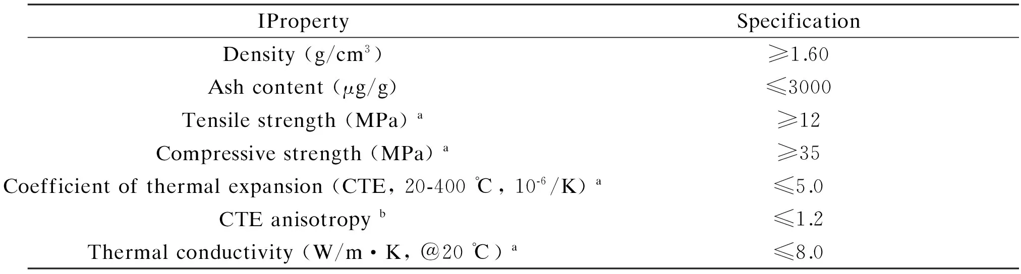
Table 6 Main property requirements of carbon bricks (with boron) for HTR-PM.
5 Future development of carbon materials for HTR
Table 7 summarizes the different kinds of carbon materials and their vendors used in the 200 MWeHTR-PM. The general amount requirement of carbon materials in the initial and start-up stages of HTR-PM is nearly 1 800 tons. After the reactor reaches criticality and operates in its full power, 60 tons of graphite powders should be provided to manufacture the matrix graphite and spherical fuel elements for HTR-PM every year.
5.1 Future prospective of HTR[21]
China Huaneng Group is the leading organization in the consortium to build the HTR-PM with China Nuclear Engineering & Construction Group (CNEC) and Tsinghua University’s INET, which is the R&D leader. Following the agreement on HTR industrialization cooperation between CNEC and Tsinghua University in 2003, the two parties signed a further agreement on commercialization of the HTR in March 2014. It’s mentioned that CNEC is responsible for the HTR technical implementation, and becomes the main investor of HTR commercial promotion in China and abroad[21]. In July 2016, CNEC signed another agreement with China Guangdong Nuclear Power Corporation (CGN) to set up a joint venture led by CNEC to develop HTRs domestically and overseas. CNEC then signed a cooperation agreement with China First Heavy Industries (CFHI or YiZhong) to support the supply chain. Thus, the initial demonstration HTR-PM will pave the way for commercial versions with three modules of each 2×250 MWtbut feeding one turbine, total 655 MWe. The HTR-PM 600 reactor units are likely to be built in pairs, so 1 200 MWe. In April 2015, CNEC announced that its proposal for two commercial 600 MWeHTRs at Ruijin in Jiangxi Province had passed an initial feasibility review[5,21]. It is reported that CNEC has done a feasibility study and commenced preliminary work on a commercial-scale HTR-PM 600 at Wan’an in Fujian Province, close to Ningde, according to CNEC subsidiary China Nuclear Industry Huachen Construction Co. This appears to be instead of Ruijin which is inland. Other feasibility studies for the HTR-PM 600 reported in September 2017 are at Sanmen in Zhejiang, Xiapu in Fujian, and Bai’an in Guangdong. In 2016, CNEC also signed agreements to develop HTRs in Saudi Arabia and Indonesia.

Table 7 Carbon materials and their vendors for HTR-PM.
5.2 Future consideration of carbon materials for HTR[5,18]
Hence, at least two commercial HTR-PM 600 will be proposed and built at home and abroad right after the construction accomplishment of HTR-PM. Concerning the supply chains of nuclear graphite relevant products are likely to be affected by international relations, to fully fulfill the localization of HTR-PM 600, the supplying of structural graphite and graphite pebbles should be through local vendors rather than international ones, to guarantee the continuity of qualities. However, at present, besides a lack of radiation data for nuclear graphite, two significant technological gaps of local graphite suppliers are involved, manufacturing procedures and qualities of raw materials. International leading suppliers of nuclear graphite that has decades of experiences accumulated had invested considerable input to enhance the manufacturing procedures and raw materials selections. Comparing with the counterparts, most of the local suppliers of graphite had been right transferred from graphite for electrode or isostatic graphite fields, which adapted in photovoltaic industries. Hence, their researches of nuclear graphite are relatively backwardness and insufficient.
Usually, nuclear graphite is manufactured from petroleum or coal-tar derived cokes and formed by isostatic molding or vibration molding to make it near-isotropic or isotropic material[4-5]. As mentioned before, the properties of nuclear graphite are directly influenced by the raw materials as well as forming methods used in the manufacture. The rigorous and precise selection of raw materials is the critical step in the preparation of nuclear graphite. It determines the structure, comprehensive properties and the performance under irradiation of the final product of nuclear graphite to a great degree. The pure raw materials should be judiciously selected to manufacture the nuclear graphite with a high chemical purity, which is essential to minimize the neutron absorption by the impurities and improve the oxidation resistance. However, commercial exploitation in coke-graphite structure relations is severely limited by the fact that standard petroleum and pitch cokes are just by-products of the petroleum and metallurgical industries, respectively. Comparing with the electrode production that is the majority market share for graphite, the current world market share of nuclear graphite is humble. Thus, the coke suppliers have less incentive in optimizing their production process for the stable manufacture of small batches of specialty coke necessary for nuclear graphite production. As we know, petroleum coke is derived from crude oil. The chemistry of a particular crude source changes over time as the fields are depleted. Oil refineries are run to optimize the production of fuels; thus, petroleum cokes made from the heavy end of the distillation process will have variable quality and properties dependent on the crude source and refinery operation. In addition, the production of pitch cokes is facing regulation risks and under increased environmental pressure to discontinue since the pollutant emissions. Consequently, the potential domestic nuclear graphite providers should choose qualified domestic petroleum or pitch coke producers to ensure the sustainable production of nuclear graphite for the future HTR applications.
As a link flow, the maximum dimension of a single structural graphite component in HTR-PM should reach 1.9×0.7×0.4 m3; hence there should be an upgraded supplying from upper stream of bulk graphite with nuclear implementation, which probably will be a challenge to the manufacture technologies of nuclear grade graphite. Meanwhile, the texture introduced during forming and thermal processes impart property variations within a billet of nuclear graphite. In addition, there are property differences between the parallel and perpendicular to the forming direction. Moreover, a density gradient should exist from center to edge of a billet. In addition, statistical variations in properties exist between billet to billet within a batch, and among production batches due to the variations in raw materials, formulations and process conditions. The inherent variability to as-produced graphite should be assessed through the analysis of large sample populations to determine the maximum range of material property variations expected for components machined from an average billet. Therefore, to facilitate the local supplying of nuclear graphite and enable it into HTR-PM 600’s implementation, for the domestic nuclear graphite vendors, the following actions should be embedded and improved in the future: enhancing the manufacturing process of nuclear graphite whilst strictly maintaining the stability and consistency; reducing the inherent variations among the performance of nuclear graphite products.
As for another three domesticated products such as carbon bricks, boron-containing carbon bricks and the graphite powders used to produce the matrix graphite and spherical fuel elements, in order to accomplish the commercial HTR-PM, there are some notable advices to optimize the related work. Taking the graphite powders as an example, artificial graphite is a raw material for producing artificial graphite powder. To obtain a stable and qualified AGP, the key is to prepare an acceptable artificial nuclear graphite which has been well documented elsewhere, and will not explore again herein. For natural graphite powder, its raw material is from natural flake graphite, a kind of natural minerals. It could be imaged the comprehensive properties of natural productions, since flake graphite from various mining areas, as a result of causing the differences in purity, impurity content and flake grain size. Even in the same area, the mining depths of natural flake graphite could bring several distinct performances. Relative to the current natural flake graphite market's main uses such as the production of expanded graphite, lithium battery anode materials and refractory materials, the market share of natural flake graphite used to prepare the natural graphite power is comparatively small. In the future, how to ensure the long-term and stable supply of natural flake graphite raw materials will be a matter that domestic manufacturers of NFGP need to pay attention. In addition, at current stage, graphite powders are prepared by mechanical pulverization, jet milling, grading and shaping processes. As a next step, how to further optimize the production process, expand the production capacity, ensure the stability of the graphite powder products, and reduce the production cost simultaneously will be the challenges that domestic graphite powder providers will face and overcome.
Fortunately, some domestic producers of carbon materials have paid more and more attentions on the manufacture and development of carbon materials particularly the nuclear graphite for HTR. The Sinosteel Advanced Materials (Zhejiang) Co., Ltd (AMC) started the irradiation test program of nuclear graphite in cooperation with Oak Ridge National Lab (ORNL) of USA in 2015[22]. As shown in Fig. 5, the irradiation program mainly includes 3 phases, i. e., the screening phase, medium dose phase and high dose phase[23]. In the screening phase, all 6 grades of nuclear graphite were irradiated to medium dose at 900 ℃. But only 2 grades of nuclear graphite underwent the post-irradiation examination (PIE) in order to enable early data for the designer. The first step of the screening phase in the irradiation test and the corresponding PIE have been completed so far. Due to the commercial confidentiality, the details of the radiation test results and the selection of samples for the 2nd and 3rd stages of the follow-up of the medium and high dose irradiation test are not disclosed. The second stage of the medium dose irradiation test at different temperatures has begun and it is expected that the radiation dose will reach the target by the end of 2018. The corresponding samples will be taken out of the reactor and start their PIE, and the other samples will continue to be irradiated within the reactor, to meet the requirements of the third stage of high dose irradiation. All the three stages of the irradiation test and corresponding PIE are estimated to take about 5 years to accomplish. Coupled with the current started oxidation and irradiation creep experiment, the entire irradiation test is expected to take 6 years or even longer. It is very important for the future localization of structural graphite in the commercial HTR-PM that the China-made nuclear graphite can start the irradiation test and obtain the comprehensive and detailed irradiation data, which also lay a solid foundation for the full localization of commercial HTR-PM in the future.

Fig. 5 Irradiation envelope for graphite irradiation program of Sinosteel AMC at ORNL [23].
Thanks for the helps of Dr. Libin Sun from INET, Tsinghua University of Beijing, China. The authors declare that there is no conflict of interest regarding the publication of this paper.
[1] Michio Inagaki, Kang Feiyu. Carbon Materials Science and Engineering—From Fundamentals to Applications[M]. Tsinghua University Press, Beijing, 2006, 3.
[2] E. Fermi. Experimental production of a divergent chain reaction[J]. American Journal of Physics, 1952, 20(9): 536-558.
[3] Physics of Uranium and Nuclear Energy: Nuclear fission[OL]. Http://www.world-nuclear.org/information-library/nuclear-fuel-cycle/introduction/physics-of-nuclear-energy.aspx (Updated December 2017).
[4] Timothy D. Burchell. Carbon Materials for Advanced Technologies[M]. Pergamon, 1999, p437.
[5] ZHOU Xiang-wen, TANG Ya-ping, LU Zhen-ming, et al. Nuclear graphite for high temperature gas-cooled reactors[J]. New Carbon Materials, 2017, 32(3): 193-204.
[6] R. E. Nightingale. Nuclear Graphite[M]. Academic press, 1962.
[7] B. J. Marsden, A. N. Jones, G. N. Hall, et al. Structural Materials for Generation IV Nuclear Reactors, Chapter 14: Graphite as a Core Material for Generation IV Nuclear Reactor[M]. Elsevier Ltd., 2017.
[8] Electricity supplied by nuclear energy[OL]. Http://www.world-nuclear.org/nuclear-basics/electricity-supplied-by-nuclear-energy.aspx (Updated November 2017).
[9] A technology roadmap for Generation IV Nuclear Energy Systems. Issued by the U.S. DOE Nuclear Energy Research Advisory Committee and the Generation IV International Forum[Z]. December 2002.
[10] X. W. Zhou, C. H. Tang. Current status and future development of coated fuel particles for high temperature gas-cooled reactors[J]. Progress in Nuclear Energy, 2011, 53: 182-188.
[11] W. Bernnat, W. Feltes. Models for reactor physics calculations for HTR pebble bed modular reactors[J]. Nuclear Engineering and Design, 2003, 222: 331-347.
[12] G. Locatelli, M. Mancini, N. Todeschini. Generation IV nuclear reactors: current status and future prospects[J]. Energy Policy, 2013, 61: 1503-1520.
[13] I. V. Dulera, R. K. Sinha, A. Rama Rao, et al. High temperature reactor technology development in India[J]. Progress in Nuclear Energy, 2017, 101: 82-99.
[14] D. Hittner, E. Bogusch, M. Fütterer, et al. High and very high temperature reactor research for multipurpose energy applications[J]. Nuclear Engineering and Design, 2011, 241: 3490-3504.
[15] Zongxin Wu, Dengcai Lin, Daxin Zhong. The design features of the HTR-10[J]. Nuclear Engineering and Design, 2002, 218: 25-32.
[16] Zuoyi Zhang, Yujie Dong, Fu Li, et al. The Shandong Shidao Bay 200 MWe high temperature gas-cooled reactor pebble-bed module (HTR-PM) demonstration power plant: an engineering and technological innovation[J]. Engineering, 2016, 2(1): 112-118.
[17] International Atomic Energy Agency, 2001. Current status and future development of modular high temperature gas cooled reactor technology[R]. IAEA-TECDOC-1198, 13-26.
[18] T. Burchell, R. Bratton, W. Windes. NGNP graphite selection and acquisition strategy[R]. ORNL/TM-2007/153, September, 2007.
[19] S. Knol, S. de Groot, R. V. Salama, et al. HTR-PM fuel pebble irradiation qualification in the High Flux Reactor in Petten[C]. International Topical Meeting on High Temperature Reactor Technology (HTR-2016), November 6-10, 2016. Las Vegas, NV, USA.
[20] Zhou Xiangwen, Lu Zhenming, Zhang Jie, et al. Preparation of spherical fuel elements for HTR-PM in INET[J]. Nuclear Engineering and Design, 2013, 263: 456-461.
[21] Nuclear power in China: High temperature gas-cooled reactors: HTR-PM, HTR-PM 600[OL]. Http://www.world-nuclear.org/information-library/country-profiles/countries-a-f/china-nuclear-power.aspx (Updated December 2017).
[22] Hui Yang, Yufa Chen, He Li, et al. Nuclear graphite development and neutron irradiation testing programme in Sinosteel AMC[C]. The 15thInternational Nuclear Graphite Specialist Meeting (INGSM-15), Hangzhou, China, September 2014.
[23] J. W Geringer, A. A. Campbell, J. D. Arregui-Mena, et al. Sinosteel AMC graphite irradiation program at ORNL[C]. The 18thInternational Nuclear Graphite Specialist Meeting (INGSM-18), Baltimore, Maryland, USA, September 2017.