Design Evaluation of Optics Valley Plaza Complex
2018-04-19HONGJing
HONG Jing
(China Railway Siyuan Survey and Design Group Co., Ltd., Wuhan 430000, Hubei, China)
0 Introduction
At present, China is in a period of vigorous development of rail transit construction. During this period, it has promoted the comprehensive development and utilization of urban underground space and brought considerable economic benefits to cities. At this critical moment, the development of the underground space around the station can not only strengthen their local functions but also improve the urban service quality of the rail transit system and provide the most liveable urban environment.
The development model for underground space of stations has been well studied. He, et al.[1]investigated the development of Shanghai Jing′an Temple Metro Station and its surrounding areas. The problems in the development of underground space were analyzed, and the method for integrating the ground and underground space in metro stations and surrounding areas were discussed from the perspective of urban design. The connection space between urban complex and metro stations was presented in the references[2-3]. These studies summarised the practical experience and trend of underground space development in the utilization of the areas around urban rail transit station in China and worldwide. Moreover, the goal of the optimal design of underground space in the urban rail transit station area was put forward based on the systematic research and analysis of primary functional compositions, space utilization forms, internal environment characteristics and related factors influencing the development of underground space. The corresponding strategies for the optimal design were proposed from the aspects of the functional organization, form layout, traffic connection and internal environment. The space and streamline of the transportation hub of urban rail transit were analyzed, and the principles of integrated design of transfer space were elaborated[4-10]. On the one hand, this can improve transfer efficiency, reduce transfer time and provide convenient travel means. On the other hand, this accords with the trend of vigorous development of green transport in China, promotes energy saving and emission reduction, and drives the integration of transport organization and functional layout with transfer space of rail transit hub station as a core. The research proposes new directions for the sustainable development of urban rail transit hub.
Based on the above research results, the full consideration is given to the existence of 5-line intersection in the Optics Valley Plaza, complicated transfer space and traffic congestion. In addition to the essential functions, this project aims to achieve optimal functions of metro and build one of the most beautiful stations in the world, according to the principle of integration of transfer space. The difficulties in the design of large underground space under complex conditions are solved by fully integrating the three functions of metro transfer, municipal tunnels and underground property development in the Optics Valley Plaza Complex.
1 Research background and scope
1.1 Research background
The Optics Valley Plaza, built in 2001, is located at the intersection of six roads including Lumo Road, Minzu Avenue, Huquan Street, Luoyu Road and Optics Valley Street in Wuchang District, forming a roundabout at the center. With the commercial development around the Plaza, the Plaza is not only a critical transportation node but also has formed the Optical Valley business circle centered on it. It has become a significant plaza of gathering, flow distribution, entertainment, recreation and exhibition. With the rapid development of urban sub-centers, the traffic growth in and out of this plaza will increase the load on the road network. Especially the traffic on the ground-level roundabout faces even more severe challenges. At the intersection of the roundabout, the traffic pressure of motor vehicles is high, and the resources of the existing roads and supporting transportation facilities are strained. Hence, it is challenging to meet and adapt to traffic requirements in both short and long terms.
According to Wuhan Rail Transit Network Planning, the extension of Metro Line 2 meets with the long-term planned Lines 9 and 11, and two tunnels of Lumo Road and Luoyu Road also pass through the plaza. The southern extension of Line 2 stretches in the east-west direction in the Optics Valley Plaza area and is laid below Huquan Street and Luoyu East Road. Line 9 in the north-south direction is below Minzu Avenue and Lumo Road, and Line 11 in the northwest-southeast direction is below Luoyu Road and Optics Valley Street, as shown in Fig. 1. The cut-and-cover excavation method is used due to the complexity of underground space, and the intersection of five lines provides the opportunities for the development of underground space together with the metro station.
According to the above urban planning, the proposed Optics Valley Plaza Complex is an "underground complex integrating transportation hubs and underground business".
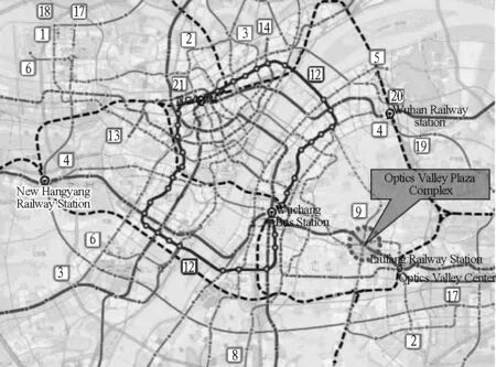
Remark: 1,2,…,21 are metro lines.
Fig. 1 Location diagram of Optics Valley Plaza
1.2 Research scope
The Optics Valley Plaza Complex is planned to have three rail transit lines, i.e., Lines 2, 9 and 11, and two municipal roads, i.e., Lumo Road and Luoyu Road expected to intersect here. Therefore, the project is the integration of three individual projects, as shown in Fig. 2.
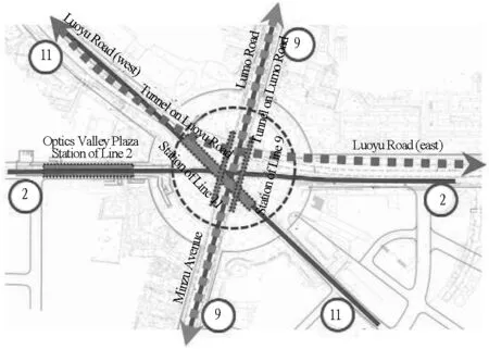
Remark: 2,9 and 11 are metro lines.
Fig. 2 Project scope of Optics Valley Plaza Complex
(1)Metro project: stations and sections of Lines 2, 9 and 11;
(2)Municipal supporting project: Luoyu Road and Lumo Road of municipal roads;
(3)Underground space project: underground non-motorized access and underground property development.
2 Control factors and design concept
2.1 Control factors
(1)Since three metro lines and two municipal roads cross each other, it must be ensured the optimal metro and traffic functions, the convenience of metro transfer and the fluency of pedestrian rules.
(2)Considering the plaza is extremely large and crowded with people, the evacuation and fire prevention should be simple and convenient.
(3)The Optics Valley Plaza Station of Line 2 has already been built at the west side of the plaza. In this way, the elevation of the starting point of southern extension of Line 2 has been determined, and the southern extension must sink at the maximum gradient to provide more space for the upper lines and transfer hall.
2.2 Design concept
Since its establishment, the Optics Valley Plaza has gradually become a vital traffic node of the Optics Valley area and the city business card of Wuhan. Based on the premise of planning conditions, the design of the Optics Valley Plaza Complex underground space is aimed to improve the status of traffic congestion and integrate new traffic patterns. In addition, it should also break through the design patterns and limitations of traditional metro stations to design it as one of the most beautiful stations in the world. The project is intended to build the Optics Valley Plaza Complex into the most beautiful landscape in Wuhan Optics Valley.
3 Design goals
Six roads are converging at the roundabout of the Optics Valley Plaza with short interweaving sections and many interweaving vehicles, resulting in heavy traffic pressure. With the rapid development of urban sub-centers, the traffic growth in and out of the plaza increases the load on the road network. Non-motorised vehicles and pedestrians have not yet constituted an integrated system. Particularly, pedestrians need to cross streets on the ground, which conflicts with traffic. Through the analysis of current traffic conditions, it is revealed that such ground roundabout cannot relieve the growing traffic pressure.
The design of the Optics Valley Plaza Complex is aimed to build a three-dimensional traffic complex with the opportunity for rail transit construction, integrating motor vehicles, non-motor vehicles and pedestrian traffic organizations. Thus the congestion of vehicles and passengers can be fundamentally improved. For the traffic organization of motor vehicles, it is decided to take separation methods, namely, separating the car flow in the main direction (Lumo Road and Luoyu Road). The rail transit network is incorporated into the Complex. Passenger flow pressure in the Optics Valley Plaza Station of Line 2 is eased by reasonably organizing transfer entrance and exit as well as transfer paths. Non-motorised vehicles will use underground passage to reduce the traffic interweaving efficiently. Independent transport systems are established for the convenience of neighbouring pedestrians crossing streets under the ground.
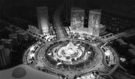
The design of the entire Optics Valley Plaza Complex will eventually efficiently relief the traffic pressure on the ground roundabout. Moreover, an urban sub-center is created with well-ordered traffic and beautiful urban landscape. A plaza complex as a model for low-carbon transportation is built through the rational use of spaces above, on and under the ground, as shown in Fig. 3.
4 Derivation of the scheme
4.1 Main design ideas
4.1.1 Scheme for Lumo Road and Luoyu Road
The analysis shows that Luoyu Road is in the same direction as the southern extension section of Line 2, which can be merged with the plane layer of the south extension section in the Complex. Lumo Road goes in parallel to Line 9. If an elevated road is constructed, it will greatly affect the landscape of the Optics Valley Central Plaza. In this case, Line 9 is to be designed as a side platform to reduce burial depth and save investment. Thus, the Luoyu Road tunnel is located between two-side platforms under the plaza. It can not only maintain the original ground landscape but also reduce the burial depth and simplify the relationship among lines.
(a) Airscape

(b) Sectional view
Fig. 3 Building design rendering of Optics Valley Plaza Complex
4.1.2 Analysis of the relationship of the floor height among three metro lines (Lines 2, 9 and 11)
Since the Optics Valley Plaza Station of Line 2 has already been built, the southern extensions of Line 2, Line 9, Line 11 and municipal tunnels are all new projects. Thus, the elevations of starting rail surfaces have been determined at about 14.802 m for the Optics Valley Plaza Station of the southern extension line and Luoxiong Road Station, and the elevation of the road is fixed at approximately 30 m. Therefore, the southern extension section is located on the third floor under the ground of the Optics Valley Plaza, and Luoyu Road tunnel is arranged on the same floor with the southern extension section.
The road tunnel running beneath Luoyu Road and the station of Line 9 are on the same floor. To facilitate the transfer, passengers need to go to the paid area for the transfer between Lines 9 and 2. Therefore, the underground space of the Optics Valley Plaza Complex is arranged with the platform of Line 9, southern extension section floor of Line 2 and the platform of Line 11 from top to bottom, as shown in Fig. 4.

Fig. 4 Analysis diagram of hierarchical relationship (unit: m)
4.1.3 Formation of the scheme for optimal metro functions
The Optics Valley Plaza Complex is designed for a three-line transfer complex among the southern extension of Line 2, Line 9 and Line 11. Besides, the Optics Valley Plaza Station of Line 2 has already been implemented, and it is approximately 260 m away from the center of the roundabout in the Optics Valley Plaza. From the aspect of optimal metro function, repeated research is conducted on 3-line transfer mode. After comparing station positions, the stations of Line 9 and Line 11 are finally decided to be set at the center of the roundabout. As a result, transfer distances are shortened, and transfer space nodes are optimised, which achieve that the passengers can transfer quickly and comfortably in such a large space.
After further analysis and comparison, the designers found that the adjustment of station positions and hall forms on the plane do not significantly improve metro functions. It is impossible to avoid the separation of transfer hall by Line 9 and eliminate the inconvenience of transfer fundamentally. Therefore, the designers turned to space adjustment to achieve optimal functions of metro. The platform of Line 9 is lifted to the mezzanine of the first floor under the ground to prevent the transfer hall separating. As a result, the entire first floor is used for transfer and transportation. The final space layout is shown in Fig. 5.
(1)The first floor under the ground is used as transfer hall for the southern extensions of Line 2, Line 9 and Line 11 as well as public space;
(2)The platform of Line 9 and Lumo Road tunnel are located both on the mezzanine of the first floor under the ground;
(3)The southern extension of Line 2 and Luoyu Road tunnel are arranged both on the second floor under the ground as well as the transfer hall and station equipment area;
(4)The platform of Line 11 is arranged on the third floor under the ground.
4.1.4 Research on project scale
The main contour of the Complex is currently reduced to a circle with a diameter of 200 m to ensure the smooth and rapid implementation of the project after further research, based on the full consideration of project scale, function positioning, municipal pipelines, traffic desorption and construction site. Hence, the project can achieve effective coordination of functions, pipelines, transportation and construction, as shown in Fig. 6.

Fig. 5 Sketch diagram of spatial layout

Fig. 6 Research and analysis of project scale (unit: m)
4.1.5 Scheme for underground property development
As known, the intersection of Luoyu Road Tunnel and the southern extension section of Line 2 crosses the Optics Valley Plaza Complex in the east-west direction and is constructed by the cut-and-cover excavation method. The space above the municipal tunnels and the southern extension is planned to make full use of the underground space and to enhance the commercial value of the underground space depending on the steady passenger flow. Underground property development is planned in the east and west wings of the Optics Valley Plaza.
4.2 Construction scheme for underground space of the Optics Valley Plaza Complex
4.2.1 General layout design
The boundary line of roads is a circle with a diameter of 300 m at the Optics Valley Plaza. The Complex is designed to have an external outline of 200 m in diameter and is connected with the surrounding plots by using sunken plazas outside the 200 m diameter. The sunken plazas adopt "cat ear" shapes as entrances and exits of the underground space to attract passenger flow in all quadrants. Fifteen meters pipeline rerouting path is also reserved beyond the "cat ear" in the range of the roundabout. The central area maintains the existing green landscape of the central plaza with a diameter of 160 m. Evacuation ladders are set up around the central plaza to meet evacuation requirements of the Complex. The roof panel is equipped with a skylight for letting in natural light and discharging smoke.
There are auxiliary buildings such as sunken courtyards, entrances and exits, and station pavilions on the outer side of roads at the roundabout. The site plan is shown in Fig. 7.

Fig. 7 Site plan of Optics Valley Plaza
4.2.2 Plan and sectional design
The Optics Valley Plaza Complex is a three-floor underground side-island transfer station. The first floor under the ground includes a circular hall with a diameter of 200 m, property development above Luoyu Road and transfer lanes of Line 2. In addition, the platform of Line 9, circular evacuation walkway and Lumo Road municipal access is in the mezzanine level of the first floor under the ground. The second floor under the ground includes the southern extension section of Line 2, the Luoyu Road municipal tunnel, the metro transfer hall and the equipment room. The third floor under the ground is used as the platform of Line 11. The plans of the first, second and third floors under the ground are shown in Fig. 8.
The southern extension section is designed to sink at a maximum slope (29 ‰) to ensure the minimum height of transfer hall of Line 9 on the first floor under the ground.
Due to the requirement of 0.3-m thick soil covered the intersection of Lumo Road, the pavement should be elevated by around 0.7 m to reach the required thickness. Meanwhile, the line-of-sight analysis in all quadrants shows that the pavement elevation will not cause interference of sight line among the plots and have no impact on the landscape of the Optics Valley Plaza. The southern extension line profile is shown in Fig. 9.
4.2.3 Transfer design
The Optics Valley Plaza Complex solves the problem of metro transfer successfully under complex conditions. The efficient transfer among three metro lines is ensured by the people-oriented design and reasonable organization of the ground and underground traffic paths, as shown in Fig. 10.
A transfer from the existing Optics Valley Plaza Station of Line 2 to Lines 9 and 11 can be described as follows. A transfer channel is set up to connect the paid area of the Optics Valley Plaza Station of Line 2 and the circular paid area on the first floor under the ground of the Optics Valley Plaza Complex. Transferring passengers can go to the circular paid area on the first floor under the ground by following the transfer channel, and then go up to the mezzanine of the first floor under the ground for transferring to Line 9 and down to the third floor under the ground for transferring to Line 11.

(a) Plan of first floor under ground

(b) Plan of mezzanine of first floor under ground (c) Plan of second floor under ground

(d) Plan of third floor under ground

Fig. 9 Sectional view of Optics Valley Plaza Complex

Fig. 10 Sketch diagram of transfer line paths
A transfer from Line 9 to Line 11 can be performed as follows. Passengers can go down to the circular paid area on the first floor under the ground from the platform of Line 9 in the mezzanine of the first floor under the ground by escalator and further down to the platform on the third floor under the ground. Other passengers can go down to the transfer hall on the second floor under the ground from the circular paid area by escalator and further down to the platform of Line 11 on the third floor under the ground for transfer.
5 Difficulties in fire protection design and corresponding strategies
A transfer from Line 9 to Line 11 can be performed as follows. Passengers can go down to the circular paid area on the first floor under the ground from the platform of Line 9 in the mezzanine of the first floor under the ground by escalator and further down to the platform on the third floor under the ground. Other passengers can go down to the transfer hall on the second floor under the ground from the circular paid area by escalator and further down to the platform of Line 11 on the third floor under the ground for transfer.
5.1 Difficulties in fire protection design
The station in the Optics Valley Plaza Complex is a large station with three lines transfer, which has a large passenger flow and requires more space for passengers to wait and transfer. In this project, underground station platform and public area of the station hall is zoned as a fire protection zone with a total area of 41 813 m2. Besides, the public area of the circular station hall on the first floor under the ground covers 31 015 m2. Subject to Item 4 of Article 7.3.18 ofTechnicalCodeofUrbanRailTransit(GB 50490-2009)[11], if multi-line transfer stations share the public area of a station hall with an area more than 2.5 times the public area of a station hall of single-line standard station, necessary fire protection measures shall be taken through performance-based fire safety design analysis. Therefore, according to this item, necessary fire protection strategies are proposed to solve the problem that the fire zone of the metro station in the Optics Valley Plaza Complex is excessively large and ensure its fire safety.
5.2 Main strategies for fire protection design
5.2.1 Fire and smoke compartmentation
(1)Separation of the station and property development in the east and west wings of the Complex: The property development area is connected with the circular hall on the first floor under the ground using channels to avoid the fire propagating between the Optics Valley Plaza Complex and surrounding property development area. Moreover, two fire shutters of fire resistance period no less than 3 hours are equipped at the distance of no less than 12 m from each other. In the event of a fire, the above measures can separate the property development area and metro station. The design of east and west properties in the Optics Valley Plaza Complex satisfies the requirements ofCodeforFireProtectionDesignofBuildings(GB 50016-2014)[12].
(2)Separation of metro station and surrounding tunnels: The tunnels on Lumo Road and Luoyu Road are also designed in strict accordance with theCodeforFireProtectionDesignofBuildings(GB 50016-2014). Moreover, the municipal tunnels and metro station are separated with fire barriers of fire resistance period no less than 3 hours, forming completely independent space.
(3)No shops are allowed in the circular hall to avoid the shop fire on the first floor under the ground spreading to the public area of the station hall.
(4)Two fire shutters of fire resistance period no less than 3 hours are installed at transfer channels of Line 2 to prevent the fire spreading between Line 2 and the public area of the circular hall, which will fall when there is a fire.
(5)The two places are separated by a fireproof glass of fire resistance period no less than one hour to prevent the fire spreading between the station hall on the first floor under the ground and the platform of Line 9.
5.2.2 Fire evacuation in public area of metro
The maximum evacuation distance should be no more than 50 m from any point in the public area of the station hall and platform to evacuation exit and evacuation stairway[13].
Thirteen security exits are leading to the ground, and fire-protection evacuation walks in the public area on the first floor under the ground, as shown in Fig. 11. The fire-protection evacuation walks are arranged in the mezzanine of the first floor under the ground without interfering with non-motorized vehicle lanes and 24-hour passages. Meanwhile, it helps optimise the surface facilities of the underground space and improve the ground landscape, as shown in Fig. 12.
5.2.3 Smoke control design
Automatic smoke exhaust skylights are installed above the full-height area on the first floor under the ground and the platform of Line 9. Their distance should not exceed 30 m from any point on the first floor under the ground, and its openable area should be no less than 5% of the total area of the first floor under the ground. Automatic smoke exhaust windows are also provided above the rail area of Line 9 for discharging hot air from the metro to the outside and letting out smoke in case of a fire. Therefore, natural ventilation is planned to be used for the area (full-height hall, the platform of Line 9 and station hall below it) on the first floor under the ground except for equipment area as well as for circular escalator openings on the second floor under the ground. Each natural smoke ventilation (window) is equipped with a manually operated device. The layout of the natural smoke vents is shown in Fig. 13.
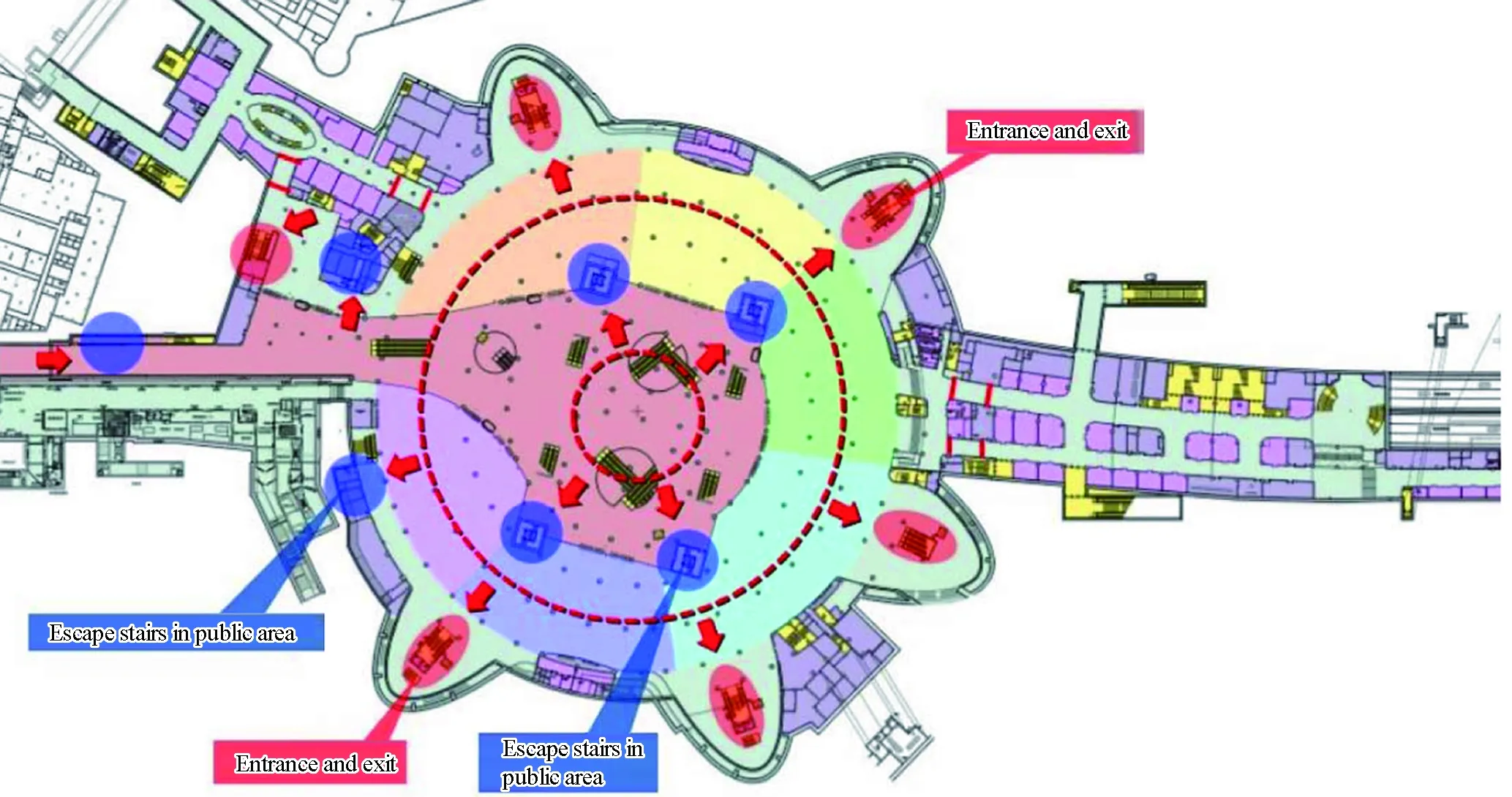
Fig. 11 Fire evacuation facilities in circular station hall on the first floor under the ground
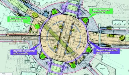
Fig. 12 Fire-protection evacuation walks in the mezzanine of the first floor under the ground

Fig. 13 Sketch diagram of natural smoke exhaust skylight
6 Conclusions and reflections
In this paper, the design difficulties in functional organisation, dynamic layout, traffic path optimisation and fire protection design of complex underground space are solved through profound analysis of design goals and derivation of schemes for the Optics Valley Plaza Complex. The followings are some ideas that will be helpful for the scheme design of similar projects:
(1)An integrated design method should be used to construct a three-dimensional organization model and minimize the traffic path crossing when designing the comprehensive underground transportation hub under complex conditions.
(2)Primary functions and orientation of the project have to be explicit. As a large comprehensive transportation hub, it is necessary to ensure that metro transfer is convenient and fast, passenger paths in good order, and evacuation and fire prevention means are simple and convenient.
(3)Great attention should be paid to the fire protection design. Effective fire separation measures shall be adopted to ensure the independence and safety of the station and other underground space.
(4)Designers are encouraged to break through the routine to create a favourable underground environment. For example, the Optics Valley Plaza Complex project achieves considerable headroom and long-span space effects. The main body of the station is built with a structure of continuous 15 m and a maximum span of 26
m, which dramatically enhances the quality of underground space and makes passengers feel comfortable as well.
(5)In the trend of vigorous development of green buildings in China, natural lighting and ventilation are recommend to be applied as much as possible in the design, which provides new ideas for similar projects in the future.
:
[1] HE Lei, SHU Yu, WANG Xuan. Investigation on urban design with integration of above-and under-ground space around subway station[J].Chinese Journal of Underground Space and Engineering, 2006, 2(7): 1199.
[2] YAN Liu. Research on the design of space for convergence between urban complex and subway station[D].Chengdu: Southwest Jiaotong University, 2016.
[3] YANG Hongqiao.Research on optimization design of under-ground space of urban rail transit station area[D].Beijing: Beijing University of Civil Engineering and Architecture, 2012.
[4] WANG Shan, YANG Jieru, WANG Jin. Research on exploi-tation and utilization of transit hub′s underground space[J].Huazhong Architecture, 2011(11): 38.
[5] DING Yuanyuan. Research on the transfer space intergration design of rail transit hubs[D]. Beijing: Beijing Jiaotong University, 2014.
[6] WANG Quan. Urban rail transportation hub space and stream-line research[D].Qingdao: Qingdao University of Technology, 2014.
[7] CUI Gan. Preliminary study of the transfer space organization optimization design of rail transit hubs[D]. Beijing: Beijing Jiaotong University, 2016.
[8] ZHOU Lixia. Theoretical analysis and study of spatial design for subway[D].Beijing: Tsinghua University, 2007.
[9] GUO Xiaofang.The research of human-oriented design for subway space[D].Zhengzhou: Zhengzhou University, 2014.
[10] LU Shanshan. Study of the humanization design of underground space in the subway station[D]. Wuhan: Wuhan University of Technology, 2007.
[11] Technical code of urban rail transit: GB 50490-2009[S]. Beijing: China Architecture & Building Press, 2009.
[12]Code for fire protection design of buildings: GB 50016-2014[S]. Beijing: China Planning Press, 2014.
[13] Code for design of metro: GB 50157-2013[S].Beijing: China Architecture & Building Press, 2013.
杂志排行
隧道建设(中英文)的其它文章
- 泥水盾构水平直管内石碴起动速度研究
- Statistics of Railway Tunnels in China as of 2017
- Key Rock Mechanics Problems and Countermeasures on Huge Diversion Tunnel of Baihetan Hydropower Station
- Study of Design and Construction Technology of Ultra-large-span Tunnel at Badaling Great Wall Station
- Innovation and Future Application of Mechanized and Intelligentized Construction Technology for High-speed Railway Tunnels: A CaseStudy of Hubei Section on Zhengzhou-Wanzhou High-speed Railway
- 水中悬浮隧道概念设计及动力分析理论与模型试验进展
