Numerical algorithm for rigid body position estimation using the quaternion approach
2018-04-18MiodragZigicNenadGrahovac
Miodrag Zigic·Nenad Grahovac
1 Introduction
Accurate rigid body attitude estimation is of a great importance in aerospace,marine and automotive engineering,autonomous robotic systems and human movement analysis.Position and orientation determination of unmanned aerial vehicles(UAVs),which have become part of daily life,and which are used as toys,or to perform different tasks and missions in both the civilian and the military sectors,is essential,see Ref.[1].For these purposes,different positioning and navigation systems are developed.An inertial measurement unit(IMU)is a device containing accelerometers and gyroscopes,used for measuring the angular velocity of a body and the acceleration of its point in the body reference frame.Some of the devices enable measuring the Earth’s magnetic field as well.From these data the body attitude needs to be determined.Measurement errors varies and depend on the type of IMU.Contrary to high-quality and expensive inertial navigation systems,the popularity of miniature low-cost inertial sensors has increased due to recent technological development.However,the latter devices are not so accurate as the former ones.Also,small errors in output data accumulate and grow with time and distance,see Ref.[2].Thus,a lot of effort has been made by both industry and the scientific community in order to improve resultsofapplicationsoflow-cost inertial devices.In the direction of reducing the errors,different filtering techniques are developed,see Refs.[3,4].In this manner,Chao et al.[5]performed a comparative study of low-cost IMUs,including both hardware and software solutions.The rigid body state estimation problem using low-pass sensors is observed in Ref.[6].Comparison of a gyroscope vs.an accelerometer measurement and investigation in which only accelerometers are used for computation of linear and angular motions of a rigid body are presented in Refs.[7,8].The scheme for rigid body position estimation using the Lagrange-d’Alambert principle from variational mechanics is proposed in Ref.[9].Low-cost wearable sensors,such as IMUs,are widely used in biomechanics,see Refs.[10,11].Their usage for rehabilitation purposes are studied in Ref.[12].Accurate orientation tracking of ahuman body parts,by the use of inertial and magnetic sensors,is presented in Ref.[13].An application of IMU in a gait monitoring is analyzed in Ref.[14],while Esser et al.[15]studied their application to determine the center of mass acceleration during human walking,using the quaternion representation.
Quaternions represent an excellent tool for describing arbitrary rotations in space,without singularities.The name of quaternion denotes a quadrinomial expression,where one term represents the real part,while the other terms together stand for the imaginary part,see Ref.[16].Analytical properties of quaternions and their application in mechanics,computer vision,graphics,and animation can be found in numerous papers,see for example,in Refs.[17–20].The quaternion approach for a rigid body attitude estimation in bio-logging,in order to determine an animal’s movements and behavior,via IMU attached to the animal,is presented in Refs.[21,22].Expressions of physical quantities,such as angle of rotation,velocity,acceleration and momentum,in quaternion space,are given in the paper of Chou[23].Recent results in the field of rigid body dynamics in terms of quaternions are presented in Refs.[24,25]via Hamilton’s equations,while both Lagrange’s and Hamilton’s frameworks are used in Ref.[26].Equations of motion of a rigid body derived from the D’Alambert’s variational principle using quaternions are analyzed in Ref.[27].Equations of motion in the last four mentioned papers assume the form of differential-algebraic equations,due to the algebraic constraint.Contrary to the analysis of the rigid body dynamics by quaternion parameters,in this study quaternions are used in rigid body kinematics,i.e.,for determination of a rotation matrix.We propose the numerical algorithm for estimation of both a rigid body orientation and the linear acceleration of an arbitrary point of the body,based on the quaternion approach,which can be easily applied to a wide class of engineering problems.
2 The problem
The free motion of a rigid body is considered.In order to estimate its attitude two coordinate systems are introduced:a nonmoving(inertial)reference frameOξηζwith unit vectorsλ,μ,νand a reference frameC x yzwith unit vectorsi,j,k,which is fixed to the body and moves together with it,where the pointCrepresents the center of mass of the rigid body,Fig.1.An IMU is located at an arbitrary pointAof the body,providing the projections¨x A,¨y A,¨z Aof the absolute accelerationa A,as well as the projectionsωx,ωy,ωzof the angular velocityωof the body onto the moving axesx,y,z.

Fig.1 Free motion of a rigid body,inertial reference frame Oξηζ and moving reference frame C x yz
The task is to determine both the accelerationa Cof the center of massC,and the accelerationa Bof an arbitrary pointBof the body,as well as its attitude,expressed in the inertial reference frameOξηζ,on the basis of¨x A,¨y A,¨z Aandωx,ωy,ωzobtained from the IMU.
Let the position vectors of the center of massC,of the pointAwhere IMU is mounted and of an arbitrary pointBof the rigid body,relative to the moving reference frame be denoted as

Following considerations of a rigid body kinematics,the acceleration of pointAcan be written as


where the acceleration of pointArelative toC,using the Rivals theorem,reads

whereωand˙ωstand for the angular velocity vectorω=ωx i+ωy j+ωz kand angular acceleration vector˙ω=˙ωx i+˙ωy j+˙ωz k,whiler CA=x CA i+yCA j+zCA krepresents the position vector of pointArelative to the mass centerC,expressed by unit vectors of the moving coordinate system.Further,a Creads

denote the terms multiplying unit vectorsi,j,kwhen the cross productω×r CAfrom Eq.(4)is evaluated.Finally,the acceleration of pointCcan be written as

where the projections ofa Con the moving axes are


The acceleration of pointCexpressed in the inertial coor-
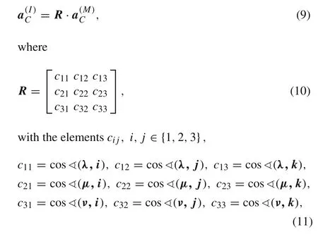
which represent the cosines of the angles between corresponding moving and nonmoving axes.
Sometimes,it is necessary to determine the acceleration of some other point,which does not coincide either with the center of massCor with the pointA,in which IMU is mounted.For determination of acceleration of such a point,sayB,whose position vector relative toCis known and given asr CB=x CB i+yCB j+zCB k,we can use the expressiona B=a A+a AB,i.e.,the procedure very similar to the one presented by Eqs.(4)–(9).It should be noted that it is possible to determine the accelerationa Busing the calculated acceleration of the center of mass,but in order to achieve higher degree of accuracy in engineering applications,it is better to use data obtained from the IMU directly,which is positioned at pointA.Therefore,the acceleration of pointBcan be expressed as
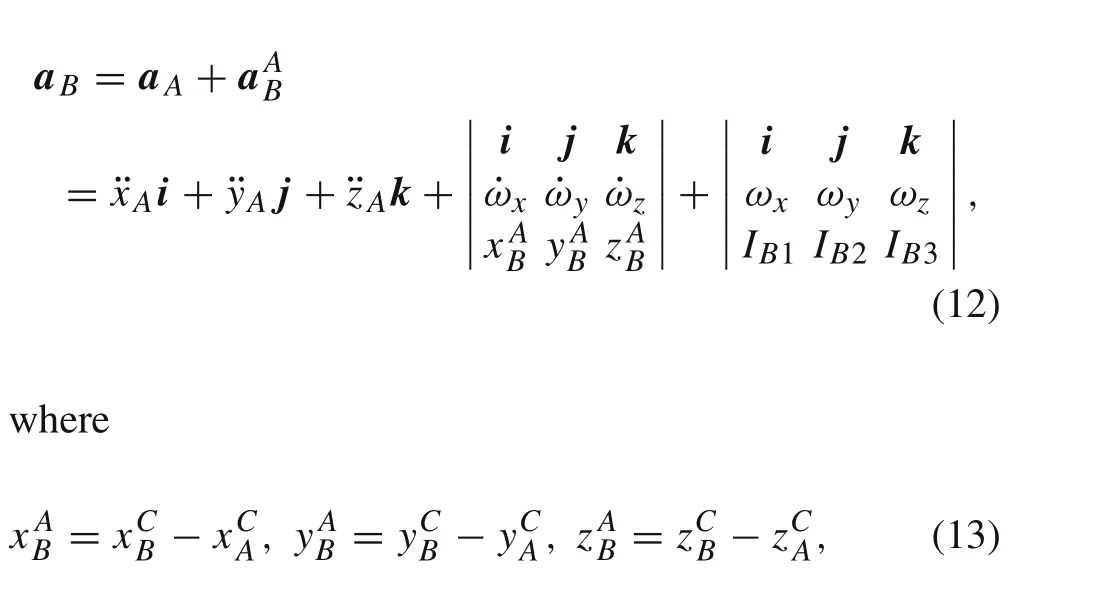
and termsIB1,IB2,IB3,similar to Eq.(6),are given as

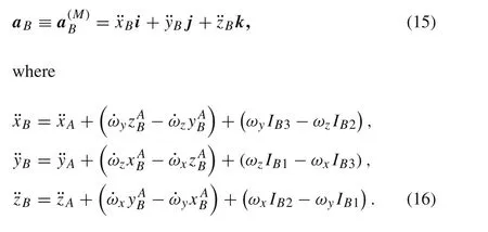
Accelerationa Bin a moving reference frame reads


3 Estimation of rigid body attitude
In order to determine the acceleration of some point of a rigid body in the inertial coordinate systemOξηζ,in addition to knowing the acceleration of that point in a coordinate system,which moves together with the bodyC x yz,it is necessary to estimate the attitude of the body in three dimensional space,i.e.,the orientation of a moving reference frame relative to the inertial one.For that purpose the theory of quaternions will be applied.It is widely used in various fields due to compactness and simple implementation into numerical algorithms.By using quaternions for a rigid body attitude estimation,the singularity problem(which can arise when Euler angles are used)is avoided,see Ref.[28].The discovery of quaternions is related to William Rowan Hamilton and the middle of XIX century,but their intensive application started more than hundred years later,in classical mechanics,flight simulations,computer graphics,and virtual reality,see Ref.[19].The rotation matrixRwill be determined by the use of that theory.
There are different ways for interpretation of quaternions.On the one hand,they can be considered as a combination of a scalar valueq0and a vectorv=v1e1+v2e2+v3e3,as follows

wheree1,e2,e3stand for base vectors of the nonmovable coordinate system,or in a vector form

in whichq0,q1,q2,q3are often called the Euler parameters[28–30].If Euler’s theorem is taken into account,which states that the rotation of a rigid body about a fixed point may be expressed as a rotation about some axesχwith the unit vectorvfor an angleδ,then the quantitiesqi(i=0,1,2,3)from Eq.(19)can be written as

The parameterq0refers to the angle of rotation about the axisχ,while the remaining three parametersq1,q2,andq3take into account both the angle of rotation and the orientation of the axisχrelative to the nonmovable reference frame.According to the Euler’s statement that any rotation of a rigid body about a fixed point can be described by three values,then there is a relation between four parametersq0,q1,q2,q3,which reads

in which case the quantityqis a unit quaternion,with unity norm,see Ref.[28].
On the other hand,quaternions can be addressed as quadrinomial expressions consisting of a real and an imaginary part.The former can be considered as a scalar value,whose square is always positive,while the square of the latter part is always negative[16].Actually,v1,v2,andv3are real coefficients,whilee1,e2,ande3represent imaginary units,which satisfy the following relations

More about quaternion algebra can be found in Refs.[18,28].
In the case when originsOandCof the reference frames from Fig.1 coincide during the motion of a rigid body(rotation about a fixed point),as stated in Euler’s theorem it is possible to bring the moving reference frame into coincidence with the inertial one by a single rotation for an angleδabout axisχ.Ifα,β,γare the angles between the axes of rotationχand nonmovable axesξ,η,ζ,then the rotation matrixR,for the transformation from body to inertial axes
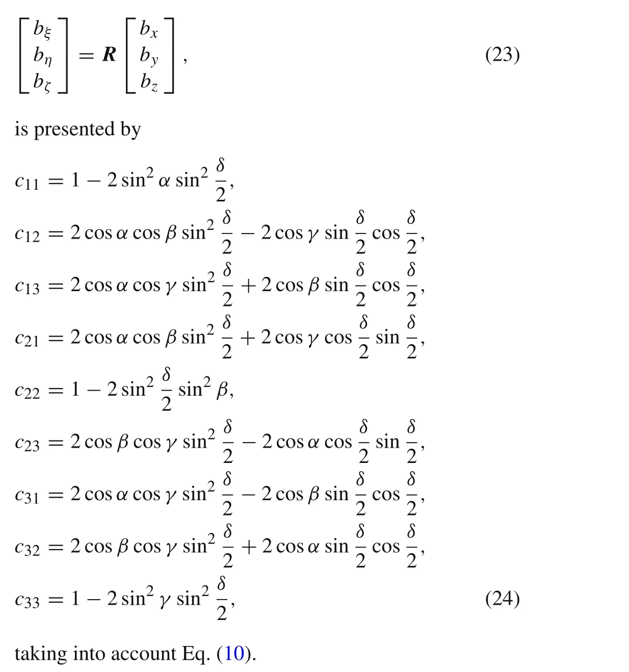
The set ofbξ,bη,bζorb x,b y,b zin Eq.(23)stands for the projections of a vector of any kind,such as position vector,velocity or acceleration,to corresponding coordinate axes.Note that in the case when the originsOandCdo not coincide,the moving axes become parallel to the axes of the inertial coordinate system,when applying the transformation given by Eq.(23).
If the following variables are introduced

the elements of the transformation matrix become
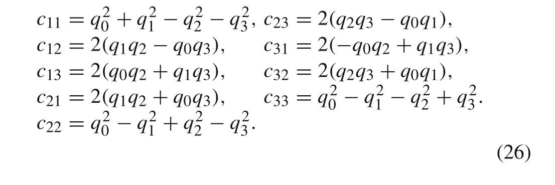
The time derivative of the Euler parameters read

Eulerangles(3,2,1)or(ψy−ya w,θp−pitch,ϕr−roll),whereψydenotes the rotation angle about initial position of axisζ,by whichξandηtake new positionsξ1andη1,θpstands for the rotation angle about axisη1bringingξ1andζ1into new positionsξ2andζ2,whileϕrdenotes the rotation angle aboutξ2,can be calculated using Euler parameters,see Ref.[29]:
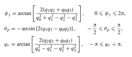
It is desirable to use the function arctan 2,with two arguments,which takes into account the appropriate quadrant of the computed angle.
For practical applications of presented considerations,it is useful to perform a time discretization,tn=n·h(n=0,1,2,...),wherehrepresents the time step,while the first derivative of a functionq0(t)over time may be approximated as

From Eq.(28)followsq0n+1=h˙q0n+q0n,so using Eq.(27)discretized Euler parameters read
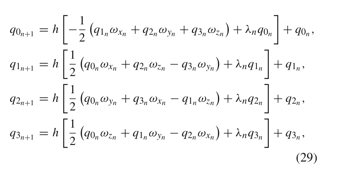

represent the numerical algorithm for determination of the Euler parameters,as well as the rotation matrixRin discrete time instants with time steph.If the movable and the nonmovable reference frames coincide at the initial time instantt=t0,the rotation angleδ0=δ(t0)=0,which implies

from Eq.(30a).For known elementscijof the rotation matrixR,by the use of Eqs.(9)and(17)it is possible to determine the absolute acceleration of the rigid body mass centerC,or the absolute acceleration of an arbitrary pointBof the body,in the inertial reference frame.Also,angular accelerations about the body axes and positions of pointsAandBrelative toCare considered as known quantities,according to Eqs.(6),(8),(14),and(16).
4 Numerical algorithm for deriving the acceleration of a point and the attitude of a rigid body


wheren=0,1,2,....The last four terms enables the calculation of the Euler parameters for the next time step,and the whole procedure repeats.For the rigid body attitude estimation,Euler angles(3,2,1)can be calculated by
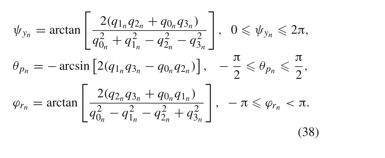
Acceleration of an arbitrary point of a rigid body a BThe algorithm for calculating the absolute acceleration of an arbitrary pointBof the rigid body,expressed in the inertial coordinate system,is presented below.Again,initial values of the Euler parameters are given by Eq.(31)for the case when the reference frames coincide at the beginning of the process.The algorithm is very similar to the previous one.Namely,the algorithm for deriving the acceleration of pointB,and rigid body attitude,is given by the following set of equations
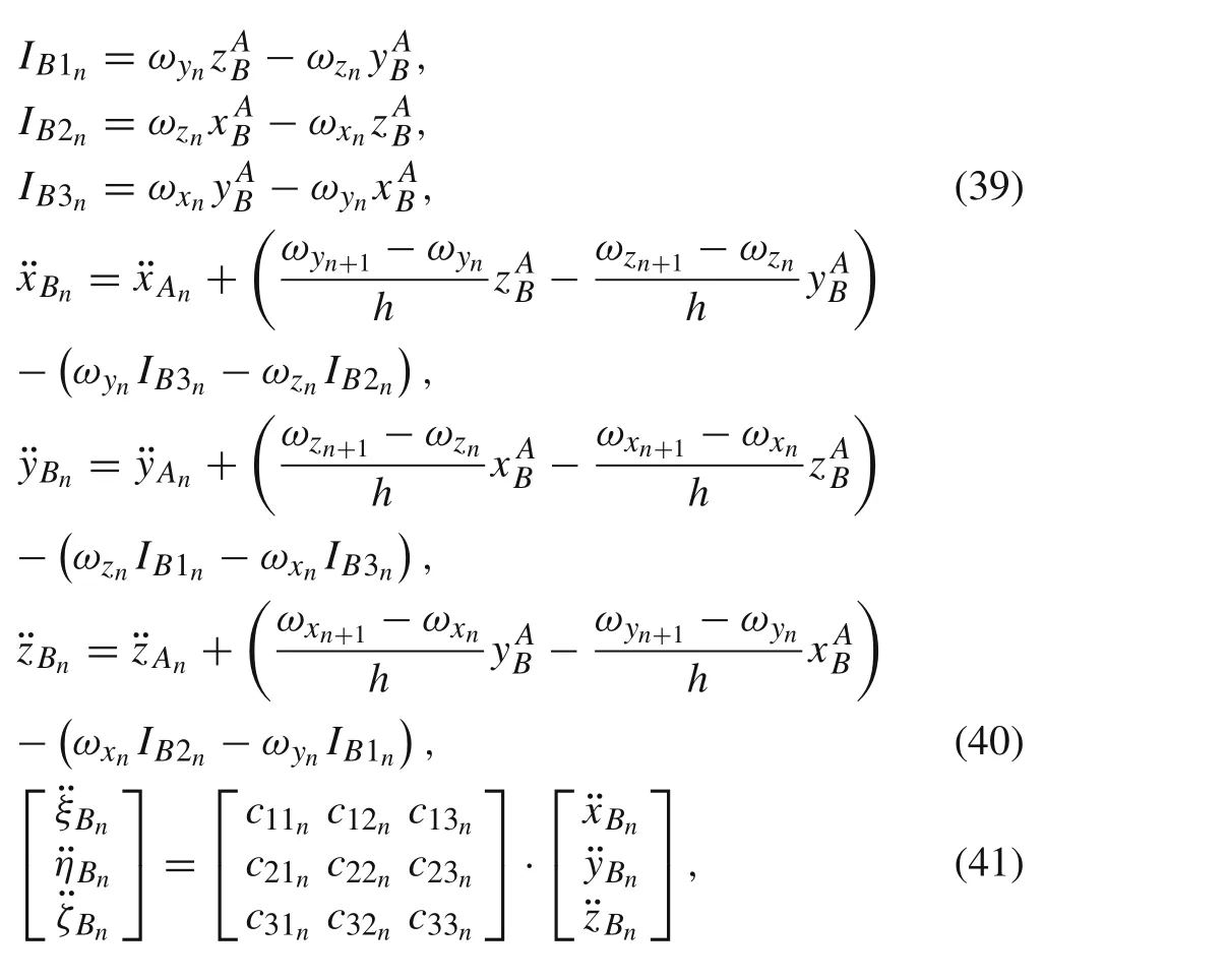
together with Eqs.(34),(35),(37),and(38),wheren=0,1,2,....
5 Numerical example:heavy symmetrical gyroscope
In this section we show an example of application of the presented algorithm given by Eqs.(32)–(37).The acceleration of a pointA(where the IMU is mounted),as well as the pro-jections of the angular velocity,are considered as known in the body reference frame.Both the attitude and acceleration of the center of massCof the rigid body in a nonmovable reference frame will be calculated.For that purpose,without loss of generality, we consider the motion of a heavy symmetrical gyroscope.A homogeneous rectangular cuboid of massmand dimensionsl1,l2,andl3rotates about a fixed pointO,which is in the center of the face with edgesl1andl2,as in Fig.2.Due to the fact that its motion can be completely determined by the use of general theory,see Ref.[32],all necessary kinematical data will be obtained by solving differential equations of motion,instead of using the IMU.Actually,the data obtained from general theory will serve as input data for the numerical algorithm presented by Eqs.(32)–(37),and for the comparison with algorithm output as well.
LagrangianLfor a heavy symmetrical gyroscope from Fig.2 reads
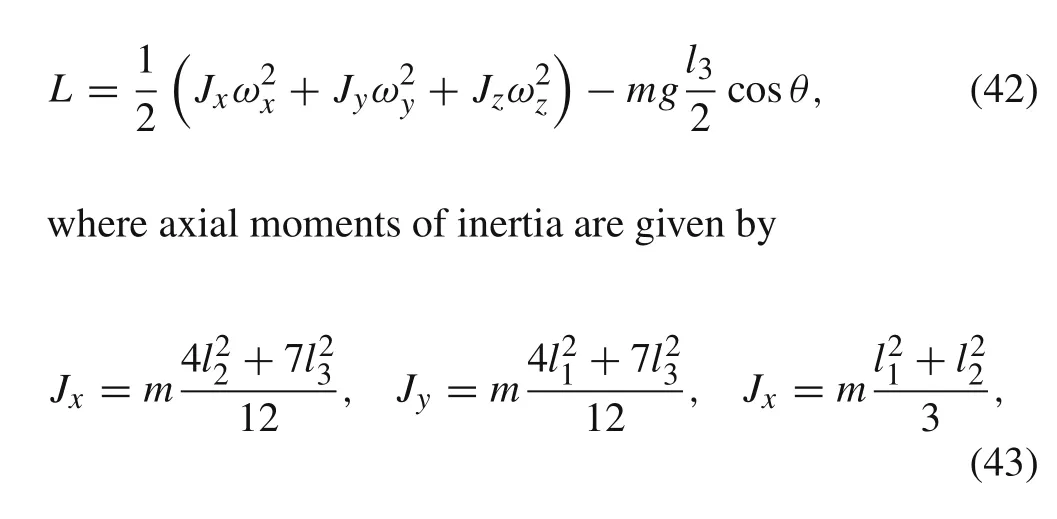

Fig.2 Heavy symmetrical gyroscope.a The initial state.b An arbitrary position with Euler angles(3,1,3)
and projections of the angular velocity to the body axesωx,ωy,ωz,by the use of Euler angles(3,1,3),read(see Fig.2b))

where the angles of precession,nutation and spin are denoted byψ,θ,andϕ,respectively.By solving the system of a three second order differential equations,derived using the well known Lagrange’s equations of the second kind


Accelerations of pointsAandCin the moving coordinate system can be calculated by using the Rivals theorem,as follows

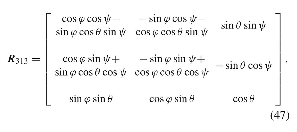
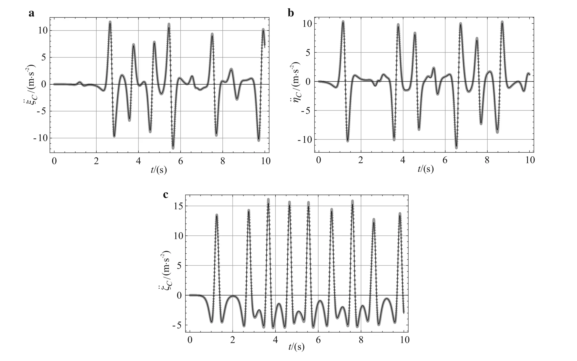
Fig.3 Absolute acceleration of the center of mass of the heavy symmetrical gyroscope.Results of the numerical algorithm are presented by dots,while the results obtained by solving the system of differential equations of motion are presented by solid lines
so the acceleration obtained by the use of general theory reads


This figure shows good agreement between the results of the numerical algorithm presented by Eqs.(32)–(37)and the results obtained by solving the system of differential equations of motion for the heavy symmetrical gyroscope.
6 Conclusion
In this paper a free motion of a rigid body is analyzed in order to determine its attitude and the acceleration of an arbitrary point of the body.We proposed the numerical procedures for calculation of the acceleration of the center of mass and any other point of the body,as well as Euler angles(3,2,1)in an inertial coordinate system,on the basis of acceleration data of a certain point of the body,sayA,and the angular velocity expressed in a body reference frame.Input data can be obtained by an IMU attached to the body,measuring kinematical data in the sensor reference frame,with axes parallel to the axes of body reference frame.The quaternion representation is used to form the rotation matrix for transformations from the body to the inertial reference frame.The advantage of application of quaternions for determination of the rotation matrix is that there are no singularities,which can arise when Euler angles are used.The initial values of quaternions are to be chosen according to the initial state of the system. The case in which the movable and nonmovable coordinate systems coincide is considered in the preceding analysis,Eq.(31).Discrete values of quaternions after the initial time instant are calculated by the presented numerical procedure.
The algorithm is applied to the problem of a heavy symmetrical gyroscope,to calculate the acceleration of the center of mass in an inertial coordinate system.Instead of using IMU,input data are obtained from the solution of the differential equations of motion given by Eq.(45)and using the Rivals theorem.By using the numerical algorithm,the rotation matrix presented by Eq.(24)is calculated during each time step and the acceleration of the center of massCis obtained in the inertial reference frame.The results are compared with the ones obtained by the application of general theory,see Eq.(48),where satisfactory agreement is achieved.The proposed numerical procedure can be applied to a wide class of problems in aerospace and marine engineering,unmanned aerial vehicles and robotic systems.
AcknowledgementsThe project was supported by the Serbian Ministry of Education,Science and Technological Development(Grant 174016).
1.Grauer,J.A.,Hubbard Jr.,J.E.:Flight Dynamics and System Identification for Modern Feedback Control.Woodhead Publishing,Philadelphia,USA(2013)
2.Barshan,B.,Durrant-Whyte,H.F.:Inertial navigation systems for mobiel robots.IEEE Trans.Robot.Autom.11,328–342(1995)
3.Beard,R.W.:State Estimation for Micro Air Vehicles,Studies in Computational Intelligence,vol.70,173–199.Springer,Berlin(2007)
4.Marins,J.L.,Yun,X.,Bachmann,E.R.,et al.:An extended Kalman filter for quaternion-based orientation estimation using MARG sensors.In:Proceedings of the 2001 IEEE/RSJ International Conference on Intelligent Robots and Systems,Maui,Hawaii,USA,October 29–November 03(2001)
5.Chao,H.,Coopmans,C.,Di,L.,et al.:A comparative evaluation of low-cost IMUs for unmanned autonomus systems.In:2010 IEEE International Conference on Multisensor Fusion and Integration for Intelligent Systems,Salt Lake City,UT,USA,September 5–7(2010)
6.Rehbinder,H.,Hu,X.:Nonlinear state estimation for rigid-body motion with low-pass sensors.Syst.Control Lett.40,183–190(2000)
7.Casson,A.J.,Galvez,A.V.,Jarchi,D.:Gyroscope versus accelerometer measurements of motion from wrist PPG during physical exercise.ICT Express 2,175–179(2016)
8.Wang,X.,Xiao,L.:Gyroscope-reduced inertial navigation system for flight vehicle motion estimation.Adv.Space Res.59,413–424(2017)
9.Izadi,M.,Sanyal,A.K.:Rigid body pose estimation based on the Lagrange–d’Alembert principle.Automatica 71,78–88(2016)
10.Luinge,H.J.,Veltink,P.H.:Inclination measurement of human movement using a 3-D accelerometer with autocalibration.IEEE Trans.Neural Syst.Rehabil.Eng.12,112–121(2004)
11.Ma,J.,Kharboutly,H.,Benali,A.,et al.:Joint angle estimation with accelerometers for dynamic postural analysis.J.Biomech.48,3616–3624(2015)
12.Madgwick,S.O.H.,Harrison,A.J.L.,Vaidyanathan,R.:Estimation of IMU and MARG orientation using a gradient descent algorithm.In:2011 IEEE International Conference on Rehabilitation Robotics,Rehab week Zurich,ETH Zurich Science City,Switzerland,June 29–July 1(2011)
13.Sabatini,A.M.:Estimating three-dimensional orientation of human body parts by inertial/magnetic sensing.Sensors 11,1489–1525(2011)
14.Santhiranayagam,B.K.,Lai,D.T.H.,Sparrow,W.A.,et al.:A machine learning approach to estimate minimum toe clearance using inertial measurement units.J.Biomech.48,4309–4316(2015)
15.Esser,P.,Dawes,H.,Collett,J.,et al.:IMU:inertial sensing of vertical CoM movement.J.Biomech.42,1578–1581(2009)
16.Hamilton,W.R.:On quaternions.Proc.R.Irish Acad.3,1–16(1847)
17.Goldman,R.:Rethinking Quaternions:Theory and Computation,Synthesis Lectures on Computer Graphics and Animation.Morgan&Claypool Publishers,San Rafael(2010)
18.Kuipers,J.B.:Quaternions and Rotation Sequences.Princeton University Press,Princeton(1999)
19.Mukundan,R.:Quaternions:from clasical mechanics to computer graphics,and beyond.In:Proceedings of the 7th Asian Technology Conference in Mathematics,Melaka,Malaysia,December 17–21(2002)
20.Spring,K.W.:Euler parameters and the use of quaternon algebra in the manipulation of finite rotations:a review.Mech.Mach.Theory 21,365–373(1986)
21.Fourati,H.,Manamanni,N.,Afilal,L.,et al.:Rigid body motions estimation using inertial sensors:bio-logging application.In:Proceedings of the 7th IFAC Symposium on Medelling and Control in Biomedical Systems,Aalborg,Denmark,August 12–14(2009)
22.Fourati,H.,Manamanni,N.,Afilal,L.,et al.:Sensing technique of dynamic marine mammal’s attitude by use of low-cost inertial and magnetic sensors.In:8th IFAC Conference on Control Applications in Marine Systems,Rostock-Warnemünde,Germany,September 15–17(2010)
23.Chou,J.C.K.:Quaternion kinematic and dynamic differential equations.IEEE Trans.Robot.Autom.8,53–64(1992)
24.Betsch,P.,Siebert,R.:Rigid body dynamics in terms of quaternions:Hamiltonian formulation and conserving numerical integration.Int.J.Numer.Methods Eng.79,444–473(2009)
25.Nielsen,M.B.,Krenk,S.:Conservative integration of rigid body motion by quaternion parameters with implicit constraints.Int.J.Numer.Methods Eng.92,734–752(2012)
26.Xu,X.,Zhong,W.:On the numerical influences of inertia representation for rigid body dynamics in terms of unit quaternion.J.Appl.Mech.83,061006-1–061006-11(2016)
27.Sherif,K.,Nachbagauer,K.,Stainer,W.:On the rotational equations of motion in rigid body dynamics when using Euler parameters.Nonlinear Dyn.81,343–352(2015)
28.Diebel,J.:Representing Attitude:Euler Angles,Unit Quaternions,and Rotation Vectors.Stanford University,Stanford(2006)
29.Durham,W.:Aircraft Flight Dynamics and Control.Wiley,New York(2013)
30.Goldstein,H.:Classical Mechanics.Addison-Wesley Publishing Company,Boston(1980)
31.Cooke,J.M.,Zyda,M.J.,Pratt,D.R.,et al.:NPSNET:flight simulation dynamics modeling using quaternions.Presence 1,404–420(1994)
32.Gantmacher,F.:Lectures in Analytical Mechanics.Mir Publishers,Moscow(1975)
杂志排行
Acta Mechanica Sinica的其它文章
- A node-based smoothed point interpolation method for dynamic analysis of rotating flexible beams
- A general solution for one dimensional chemo-mechanical coupled hydrogel rod
- Micromechanics of substrate-supported thin films
- Generalized mixed finite element method for 3D elasticity problems
- Two-dimensional analysis of progressive delamination in thin film electrodes
- Influence of layer orientation and interlayer bonding force on the mechanical behavior of shale under Brazilian test conditions
