Influence of layer orientation and interlayer bonding force on the mechanical behavior of shale under Brazilian test conditions
2018-04-18JianmingHeLekanOlatayoAfolagboye
Jianming He·Lekan Olatayo Afolagboye
1 Introduction
Studies have shown that clastic sedimentary deposits such as shale and clay are anisotropic in nature[1].Anisotropy can be either(1)inherent anisotropy that is a physical characteristic inherent in the material or(2)induced anisotropy that occurred due to the strain associated with the applied stresses.According to Ref.[2],“Shale is a clastic sedimentary rock mainly composed of silt-size and clay-size particles.Most shales are laminated and display fissility;the rock has a tendency to split along relatively smooth and flat surfaces parallel to the bedding”.Sequence of laminations occur as a result of variations in depositional environment that leads to differences grain size,clay percentage,microfossil content,organic material content,or mineral content[3].The presence of these laminar planes or laminations can have a serious effect on the mechanical behavior and strength of shale rock.This is because the lamination causes the shale rock to be anisotropic.The properties of any anisotropic rock are directionally dependent,which is different from isotropic rocks that have similar characteristics in all directions.Rock engineering activities such as hydraulic fracturing and fracture propagation,stability of underground and surface excavations,interpretation of micro-seismic monitoring,borehole stability and deformation,fluid flow and contaminant transportation are affected by rock anisotropy[4].Hence,there is proper need to understand the anisotropic behaviors of shale rock in the design of rock engineering works.
Generally,the mechanical properties of anisotropic rocks are typically determined by testing the sample of anisotropic rock cut at varying orientation with respect to the planes of anisotropy.The testing method can be uniaxial compression,triaxial compression,Brazilian test,hollow cylinder test,resonant bar method,or ultrasonic pulse method[4].As remarked by Ref.[4],“the preparation of the test specimens,their dimensions,and the minimum number of test specimens necessary to determine the properties of anisotropic rocks depend on the method used”.Of all the mechanical properties that can be derived from the above-mentioned tests,uniaxial tensile strength is a vital parameter since rocks are naturally much weaker in tension than in compression.The Brazilian tensile test is the generally accepted laboratory method to determine the tensile strength of rock materials[5–7].The method of specimen preparation in the Brazilian tensile test is not strict compared with other methods,and the analysis of the test is not difficult.The International Society for Rock Mechanics[8]had suggested procedures for determining indirect tensile strength using this test.In the Brazilian test,a disc specimen is compressed with diametrically opposite and symmetric line loads.The justification for the test is based on the experimental fact that most rocks in biaxial stress fields fail in tension at their uniaxial tensile strength when one principal stress is tensile and the other finite principal stress is compressive. The layer orientation with respect to the axis of loading plays very important roles in the mechanical response of shale under tensile stress state.
Many researchers have studied the tensile strength of anisotropic rocks using laboratory testing and numerical simulation methods.The analytical solution to measure the tensile strength of anisotropic rocks was developed by Ref.[9]based on the theoretical relation proposed by Ref.[10]between the stress and strain within a disc of anisotropic material under diametrical loading.The influences of layer orientation and layer thickness on indirect tensile strength and fracture pattern of anisotropic rocks such as sandstone and slate under diametrical loading conditions has been investigated by conducting Brazilian tests[11–15].The general conclusion from these works reveal that failure of anisotropic rocks are complicated as the tensile strength is related to the orientation of the plane of anisotropy and the failure pattern are complex.In their study,Lisjak et al.[16]used combined finite element method/discrete element method(FEM/DEM)to study the anisotropic mechanical behaviors of Opalinus Clay under Brazilian and compression tests.In the model developed by the authors,a transversely isotropic elastic constitutive law was used to describe the elastic response,and the rock fracturing was captured using discrete element method(DEM)algorithms and non-linear fracture mechanics principles.Work by Duan and Kwok[17]studied the behaviors of inherently anisotropic rocks under Brazilian test condition based on DEM simulations.In this study,DEM models were generated to represent inherently anisotropic rocks based on the bonded particle model(BPM)and smooth-joint model provided by particle flow code in two dimensions(PFC2D).Furthermore,Lanaro et.al.[18]used boundary element method code in two dimensions(FRACOD 2D),that implements the displacement discontinuity method(DDM),crack initiation,and propagation algorithms,to model Brazilian tensile tests.
This work investigates the anisotropic behavior of transversely isotropic shale rocks under the Brazilian test method using experimental and numerical approaches,as well as the structure and composition of the laminations through digital microscopy and micro-computed tomography(micro-CT).Brazilian tests on the shale were carried out in the laboratory according to the suggested method by Ref.[8].PFC2Ddeveloped by Itasca was employed to simulate the mechanical behavior of shale under Brazilian tensile condition.Particle flow models of the shale were built according to the experimental investigation of the anisotropy characteristics.The paper presents the influence of orientation of the laminations and interlayer bonding force of these fine layers on the mechanical behavior of the shale.
2 Anisotropy characteristics of the shale
Shale samples used in this study are taken from an outcrop of fossil-bearing shale of the Longmaxi Formation in the Silurian group in ShiZhu County,Chongqin,China.The shale samples are very fine-grained,medium to dark grey,hard,and transversely isotropic.The samples were cored from a block with no macro-cracking.The anisotropy of the shale depends on the relative weakness of the laminar plane and the orientation of the plane with respect to the applied stress[19].The shale has dense laminations of weak planes,normally occurring as parallel planar structures(parallel laminations).Thin rock slices were made in order to show lamination structure and the shale slices were magnified using the digital microscope for the measurement of the thickness of the shale laminations.Figure 1 shows a magnified view of the laminations in the shale.The laminations have a thickness of approximately 1.0 mm.Miniature cubic size of the shale samples(2 mm×2 mm)were scanned using micro-CT and the scanned image of the shale is shown in Fig.2.The mineral content of the laminations was investigated by tracing the boundaries of the different minerals in the micro-view of the shale and are listed in Table 1.Laminations in the shale consist of small differences in the type of sediment that occur in different grain size and mineral content.The distribution of the constituent minerals shows the difference in composition of the shale laminations as indicated by red line.The presence of relatively weak laminar plane can result in a remarkable anisotropic effect on the mechanical behavior and strength of the shale.

Fig.1 Magnified view of the shale laminations using digital microscope

Fig.2(Color online)Scanned image of the shale sample using micro-CT
3 Brazilian testing and results
The shale samples taken from the outcrop were cut into discs with a diameterDof 50 mm and the thickness of approximately 25 mm.The two ends of the cores were ground in order to meet the standard specification.The axis of the cores was set parallel to the strike of the laminar planes.The orientation angle of the lamination is defined as the angle between the laminar plane and the horizontal direction.Brazilian test was carried out in the laboratory according to the specification of Ref.[8].Two steel loading jaws were designed so as to contact the disc-shaped rock sample at diametrically opposed surfaces over an arc of contact of approximate 10°at failure(Fig.3).The triaxial rock mechanical test system TAW-2000 was used for the Brazilian tests.The rock disc was loaded continuously at a constant loading rate of200 N/s until failure.The orientation angle of the laminations of the specimen was changed from 0°to 90°at an interval of 15°.Five specimens were tested for each orientation angle since one sample may not be adequate to represent the general failure behavior corresponding to a lamination orientation.The tensile strength(Table 2)for each specimen was calculated as


Fig.3 Brazilian test set-up with sample and loading jaws
wherePis the splitting load when the rock disc fails;Dis the diameter;Bis the thickness of the rock disc.
Variation in the Brazilian tensile strength(BTS)with the inclination angle of the lamination is plotted in Fig.4.The graph shows a downward trend that is the failure strength decrease with increase in orientation of the lamination.How-ever,the tensile strength increases a little when the layer orientation increased from 75°to 90°.In addition,the average failure strength of the samples with lamination angle less than 30°(6.46 MPa)was larger compared with samples with lamination angle greater than 30°(3.46 MPa).The trend of decreasing failure strength with increase in orientation angle is similar to the experimental results of Refs.[4,12,20]on transversely isotropic sandstone.Tavallali and Vervoort[12]explained this phenomenon as follows:“when the layers are horizontal or semi-horizontal the fracture is mainly through the stronger material,while by increasing the inclination angle the fracturing processes make use of the layers,of which one could expect that they have weaker mechanical properties.In addition,it is possible that in the latter cases samples fail also in shear and not purely in tension.”Similar to the experimental results of Ref.[4],the difference between the maximum and minimum value of strength was significant(4.16 MPa).Tavallali and Vervoort[12],however,observed a relatively small difference between the maximum and minimum value of strength.
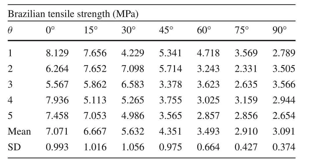
Table 2 Tensile strength of the shale specimens

Table 1 Minerals present in the laminations and the corresponding content
Different modes of fracture propagation(Table 3)led to the failure of different shale specimens,and more than one failure mode can be observed in specimens with equal lamination orientation.The following types of fracture propagation were observed after specimen failure:

Fig.4 Tensile strength of the laboratory results in comparison with the results of simulation
(1)Fracture propagation that deviated from the loading direction of the rock disks termed as curved fracture;
(2)Propagation partly along and partly through the laminar plane termed broken-linear fracture;
(3)Fractures that propagated along the laminar plane and termed as layer-activated fracture;
(4)Fracture that passed roughly along the loading direction of the rock disks termed central-linear fracture.
Curved fracture propagated in tension mode along the rock matrix.Layer-activated or broken-linear fracture propagated in mixed mode that is shearing along the laminar plane and tension in the rock matrix.Central-linear/curved fracture mainly propagated in tensile mode along the laminar plane when the orientation was 0°and in shear mode when the orientation was 90°.Some other forms of fractures werealso observed apart from the main failure fracture especially in samples with low lamination orientations.The fracture pattern is transformed from curved to broken-linear,then layer-activated,and finally central-linear fracture as the layer orientation increases.Curved fractures were commonly observed when the inclination angle was between 0°and 30°.Layer-activated and broken linear fractures were observed when the inclination angle was between 30°and 60°.Central linear fractures were observed when the inclination angle was between 75°and 90°.This indicates that the laminar structures in the shale play an important role with the increase in layer orientation.The rock matrix is replaced gradually by the laminar planes as the main controlling factor for the tensile failure process of shale.

Table 3 Some typical fracturing patterns of the shale specimens with different layer orientation
4 Numerical modeling
DEM has been widely used in civil,mining,petroleum,and geo-environmental engineering applications as it is recognized as a tool capable of simulating the progressive failure of rock and micro-mechanisms underlying the deformation behavior of rocks.It has been used to study the role of grain interlocking on the strength of a rock[21],effect of porosity on the deformability and strength[22],the impacts of fluid viscosity,particle size distribution,and the brittleness of shale on fracture propagation[23].DEM has a greater advantage over other continuum methods because it can simulate crack initiation and propagation from microscale to macro-scale without applying complex constitutive laws[24].
In this study,PFC2Ddeveloped by Itasca was used for the numerical modelling of the mechanical behavior of the shale under Brazilian test conditions.The two types of bonded particle model(parallel bond model and contact bond model)found in the program were used.In PFC2Dmodels,rocks are represented as an assembly of discs bonded at their point of contacts[25].The overall constitutive behavior of shale is simulated as an assembly of particles bonded to one another at their contact points,and the breakage of individual bonds represents damage.The stress will be redistributed when a bond breaks and this may cause further bond breakage.The induced micro-cracks can coalesce and later form macro fractures.The numerical modelling is based on the laboratory results of the anisotropy characteristics under Brazilian test conditions.The 2D numerical models used in this study were established in strict accordance with the scanning results of the different laminations by micro-CT.The layer orientation,interlayer bonding force,and mineral composition difference between layers were considered in building the numerical model for studying the mechanical behavior of shale as influenced by layer orientation and interlayer bonding force under the Brazilian tensile conditions.
The specimens used for the numerical simulation of the indirect tensile tests is a disc shape with a diameter of50 mm and unit thickness.The total number of particle is 42,102 and the particle size follows a uniform distribution withRmin=0.15 mm andRmax/Rmin=2.The particle distribution of the specimens with different inclination angles were the same.The diameter of the rock specimen was 50 times that of the laminations and the spacing between each laminae plane was about 1.0 mm.The parallel-bond model was applied to rock matrix and laminar plane,defined as an interface between two neighboring laminations,was assigned with the contact bond along which sliding and separation can occur.A contact bond is defined by the following two parameters:normal contact bond strength and shear contact bond strength.Different bond strength values were given to the rock matrix and the lamination layers to simulate the strength difference between the layers.Different microparameters were assigned to different zones,corresponding to layer and matrix,in the specimen to study the different orientation angles of the lamination planes.Parameters for the parallel bond used in the rock matrix and contactbond used in the laminar planes are listed in the Tables 4 and 5,respectively.The material strengths are picked from a Gaussian(normal)distribution for both shale matrix and laminar planes,which are specified in terms of mean and a standard deviation.A computer program based on the finite element method was employed to estimate the lamination stiffness under the condition of uniaxial compression.According to the scanned image of the shale laminations in Fig.2,different minerals,pores,and micro-cracks were considered in the numerical model and the weakness due to cementation that exist between the mineral grains were ignored in the simulation.The uniaxial compression test was simulated in the program on the neighboring laminations respectively and the different lamination stiffness was obtained.The ratio of stiffness(1.114)between the neighboring laminations was used instead of the absolute value in the subsequent modeling of the shale using PFC2D.In this numerical simulation,the anisotropy angles considered were 0°,15°,30°,45°,60°,75°,90°.The interlayer bonding force was adjusted through modifying the shear and tensile strength of the contact bonds based on the simulation,which can compare with the laboratory results.The influence of interlayer bonding force was studied through modifying the shear and tensile strength of the contact bonds to the integral multiple of the initial value from×1 to×8.

Table 4 Micro-parameters of the parallel bond to define the rock matrix
Micro-cracks that form between the bonded particles at peak stress level during the BTS test were counted and used to determine the mechanism that controlled the failure of each specimen.In PFC,micro cracks that can form when(1)the normal strength of contact bond(CN)has been exceeded;(2)the shear strength of contact bond(CS)has been exceeded;(3)the normal strength of parallel bond(PN)has been exceeded;(4)the shear strength of parallel bond(PS)has been exceeded.The number of micro-tensile and micro-shear cracks in the bonds of the parallel bond model and contact bond model were used determine the mechanism by which the models fail.The bond breaks in shearing and normal directions are plotted in red and white color respectively while the particles are plotted in black color.Some typical simulation results of the micro cracks distribution with different layer orientation are shown in Table 6.

Table 5 Micro parameters of the contact bond that define the laminar plane
4.1 Comparison of the tensile results
The variation in numerical BTS with the inclination angle of the lamination is plotted in Fig.4.As shown in Fig.4,laboratory result and simulation results show a good agreement.Apart from when the orientation of the laminar plane is 0°,the BTS of the numerical simulation is lower than the average BTS obtained from the laboratory test in other orientation angles.The numerical simulation also shows that the numerical BTS were very sensitive to the variation in the layer orientation.In addition,similar fracture patterns were observed in both the laboratory and simulation results(Table 6).Some of the typical fracture patterns observed in the numerical simulation tests are shown in row×1 in Table 6.The curved fracture pattern is observed when the layer orientation is 0°.Overall,the anisotropic behavior of the model specimens becomes more pronounced with the increase in layer orientation from 0°to 90°.The fracture pattern changes from curved to the broken-linear,then to layer-activated,and finally central-linear fracture.This indicates that the failure through rock matrix is gradually replaced by the laminar planes failure as the orientation angle increases.In addition,the specimens with smaller layer orientation angles always failure with zigzagged fractures.
The effects of layer orientation on the micro-cracks formed during the loading process in the numerical simulation are shown in row×1,Table 6.The distribution of the micro-cracks in specimens with layer orientation less than 30°were relatively symmetrical and uniform.Different deformability of the neighboring laminations result in the shearing stress accumulation in the laminar planes,thus the micro-cracks were formed due to the break of the contact bond.With increase in layer orientation,the distribution of micro-cracks became asymmetrically and non-uniformly.The ratio of micro-cracks due CS to micro-cracks due to CN showed a decreasing trend.When the layer orientation exceeded 45°,the ratio dropped to less than 1(Fig.5).This shows that the shearing breaks has transformed to the normal breaks in the laminar planes.The ratio of micro-cracks due PN to micro-cracks due to PS was more than 5 in all layer orientations(Fig.6).This indicates that bond breaks in the normal direction due to the tensile stress dominate the micro-cracks formed in the rock matrix.Most of the ratios of the breaks of PN and PS are more than 5.0,and as shown in Fig.6,this indicates that bond breaks in the normal direction due to the tensile stress dominate the micro-cracks formed in the rock matrix.
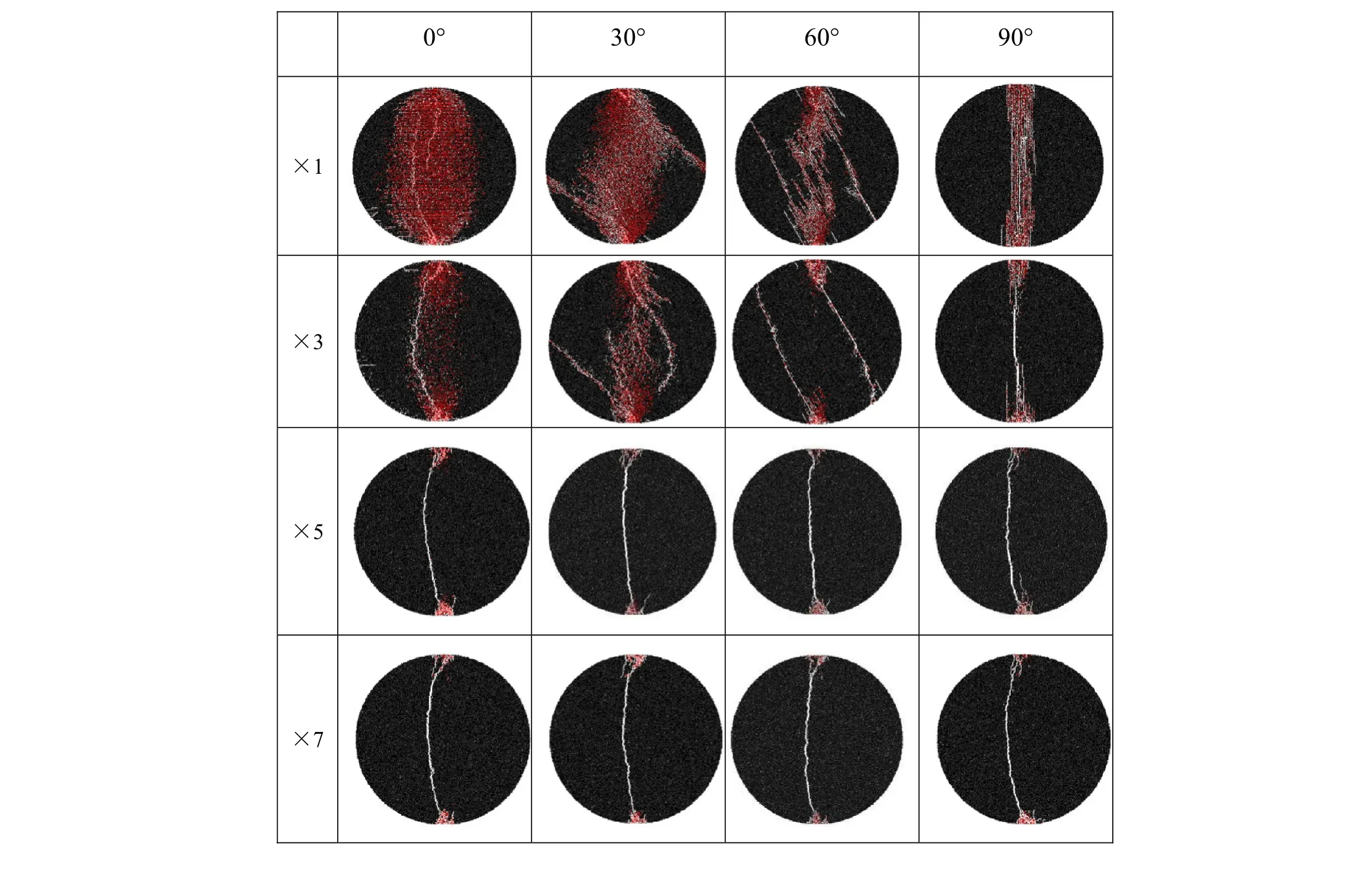
Table 6 Some typical micro-crack distributions of the simulation with different layer orientation

Fig.5 Variation of the ratio of the breaks of CS/CN against layer orientation
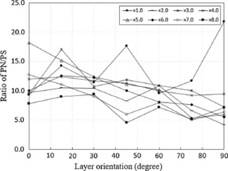
Fig.6 Variation of the ratio of the breaks of PN/PS against layer orientation
4.2 Influence of the interlayer bonding force
Special attention was paid to the influence of interlayer bonding force on the fracturing of shale under Brazilian tensile conditions.Because the rock specimens were taken from the outcrop,the bonding conditions of the lamination may vary due to heterogeneity introduced by weathering.Considering the bonding conditions of the rock disks,study on the influence of interlayer bonding force was achieved by using numerical simulation.As shown in Fig.7,the tensile strength of the different interlayer bonding forces against the layer orientations changed significantly.The layer orientation and interlayer bonding force of the shale play a very important role in the anisotropic mechanical behavior of shale.The amplitude of strength variation is much smaller in cases with layer orientation less than 30°(3.05 MPa)than cases with layer orientation more than 30°(6.44 MPa).The numerical tensile strength shows a decreasing trend in general when the interlayer bonding strength was set smaller(?×4).
Table 6(row ×3 to×7)shows the influence of interlayer bonding force on the micro-cracks formed during the loading process.The total percentage of micro-cracks due to CN and CS in laminar planes decreased as the interlayer bonding force increased in all the layer orientation(Fig.8).In contrast,the total percentage of micro-cracks due to PN and PS increased as the interlayer bonding force increased(Fig.9).The number of micro-cracks decreased sharply with the increasing of the interlayer bonding strength from×1 to×7(Table 6).This indicates that the increase in interlayer bonding strength leads to reduction in the anisotropic behavior of the shale.The bonding force distributions in the specimens corresponding to the micro-cracks simulation results(Table 7)also indicates that the anisotropic mechanical response is higher in the case of lower interlayer bonding strength(×1 and×3)compared to case of higher interlayer bonding strength(×5 and×7).

Fig.7 Tensile strength against layer orientation of the simulation results with increasing inter layer bonding strength

Fig.8(Color online)Variation in the percentage of micro-cracks of CN+CS in the total

Fig.9(Color online)Variation in the percentage of micro-cracks of PN+PS in the total
5 Conclusions
Based on experimental studies and numerical simulations,the mechanical behavior of inherently anisotropic shale rocks under Brazilian test conditions is investigated in this study.The effects of the weak lamination planes and interlayer bonding force of these layers on the failure strength and fracture patterns are examined.The laboratory failure strength decreased with increase in layer orientation angle.Four types of fracture patterns were observed:curved fracture,broken-linear fracture,layer-activated fracture,and central linear fracture.The fracture pattern is transformed from curved to broken-linear,then to layer-activated,and finally to central-linear fracture as the layer orientation increases.The observed fracture propagated in tensile and/or shear mode.The numerical simulations showed a good agreement with the experimental results in the failure strength and fracture patterns.The numerical tensile strength shows a decreasing trend in general when the interlayer bonding strength were set smaller(?×4).The distribution of the micro-cracks in specimens with layer orientation less than 30°were relatively symmetrical and uniform.The quantity of micro-cracks decreased sharply with increase in the interlayer bonding strength and this directly led to reduction in the anisotropic behavior in the mechanical properties of the shale.The failure strength,fracture pattern,micro-cracks distribution,and contact force in the specimens show obvious anisotropic characteristics in both of the laboratory and simulation results.The layer orientation and interlayer bonding force of the shale thus play a very important role in the anisotropic behavior of shale.

Table 7 Some typical bonding force distribution of the simulations with different layer orientation
AcknowledgementsThe project was supported by the National Natural Science Foundation of China(Grants 41572310,41272351,and 41227901)and the Strategic Priority Research Program of the Chinese Academy of Sciences(Grants XDB10030301 and XDB10030304).Authors acknowledge their sincere thanks to Prof.Jijin Yang and Prof.Lihui Li for their helpful microscopic information on the shale.
1.Mitchell,J.K.,Soga,K.:Fundamentals of Soil Behavior.Wiley,New York(2005)
2.Terzagi,K.,Peck,R.B.,Gholamreza,M.:Soil Mechanics in Engineering Practice.Wiley,New York(1996)
3.Boggs,S.J.:Principles of Sedimentology and Stratigraphy.Merrill Publishing Company,Westerville(1987)
4.Chen,C.-S.,Pan,E.,Amadei,B.:Determination of deformability and tensile strength of anisotropic rock using Brazilian tests.Int.J.Rock Mech.Min.Sci.35,43–61(1998)
5.Andreev,G.E.:A review of the Brazilian test for rock tensile strength determination.Part II:contact conditions.Min.Sci.Technol.13,457–465(1991)
6.Andreev,G.E.:A review of the Brazilian test for rock tensile strength determination.PartI:calculation formula.Min.Sci.Technol.13,445–456(1991)
7.Perras,M.A.,Diederichs,M.S.:A review of the tensile strength of rock:concepts and testing.Geotech.Geol.Eng.32,525–546(2014)
8.ISRM:Suggested methods for determining tensile strength of rock materials.Int.J.Rock Mech.Min.Sci.15,99–103(1978)
9.Amadei,B.,Rogers,J.D.,Goodman,R.E.:Elastic Constants and Tensile Strength of Anisotropic Rocks.In:5th ISRM Congress,ISRM-5CONGRESS-1983-030.Melbourne,Australia(1983)
10.Lekhnitskii,S.G.:Anisotropic Plates.Gordon and Breach,New York(1968)
11.Chen,C.,Pan,E.,Amadei,B.:Determination of deformability and tensile strength of anisotropic rock using Brazilian tests.Int.J.Rock Mech.Min.Sci.Geomech.Abstr.35,43–61(1998)
12.Tavallali,A.,Vervoort,A.:Failure of transversely isotropic rock material:effect of layer orientation and material properties.In:The 6th International Symposium on Ground Support in Mining and Civil engineering Construction,317–328.Cape Town,South Africa(2008)
13.Vervoort,A.,Tavallali,A.:Effect of layerorientation on the failure of layered sandstone under Brazilian test conditions.Int.J.Rock Mech.Min.Sci.47,313–322(2010)
14.Tavallali,A.,Vervoort,A.:Failure of layered sandstone under Brazilian test conditions:effect of micro-scale parameters on macro-scale behaviour.Rock Mech.Rock Eng.43,641–653(2010)
15.Tan,X.,Konietzky,H.,Frühwirt,T.,et al.:Brazilian tests on transversely isotropic rocks:laboratory testing and numerical simulations.Rock Mech.Rock Eng.48,1341–1351(2015)
16.Lisjak,A.,Tatone,B.S.A.,Grasselli,G.,et al.:Numerical modelling of the anisotropic mechanical behaviour of opalinus clay at the laboratory-scale using FEM/DEM.Rock Mech.Rock Eng.47,187–206(2014)
17.Duan,K.,Kwok,C.Y.:Discrete element modeling of anisotropic rock under Brazilian test conditions.Int.J.Rock Mech.Min.Sci.78,46–56(2015)
18.Lanaro,F.,Sato,T.,Stephansson,O.:Microcrack modelling of Brazilian tensile tests with the boundary element method.Int.J.Rock Mech.Min.Sci.46,450–461(2009)
19.Mark,D.Z.:Reservoir Geomechanics.Cambridge University Press,Cambridge(2007)
20.Tavallali,A.,Vervoort,A.:Behaviour of layered sandstone under Brazilian test conditions:layer orientation and shape effects.J.Rock Mech.Geotech.Eng.5,366–377(2013)
21.Scholtès,L.,Donzé,F.-V.:A DEM model for soft and hard rocks:role of grain interlocking on strength.J.Mech.Phys.Solids 61,352–369(2013)
22.Weng,M.C.,Li,H.H.:Relationship between the deformation characteristicsand microscopic propertiesofsandstone explored by the bonded-particle model.Int.J.Rock Mech.Min.Sci.56,34–43(2012)
23.Shimizu,H.,Murata,S.,Ishida,T.:The distinct element analysis for hydraulic fracturing in hard rock considering fluid viscosity and particle size distribution.Int.J.Rock Mech.Min.Sci.48,712–727(2011)
24.Cundall,P.A.:A discontinuous future for numerical modelling in geomechanics?Proc.Inst.Civ.Eng.Geotech.Eng.149,41–47(2001)
25.Potyondy,D.O.,Cundall,P.A.:A bonded-particle model for rock.Int.J.Rock Mech.Min.Sci.41,1329–1364(2004)
杂志排行

Acta Mechanica Sinica的其它文章
- A node-based smoothed point interpolation method for dynamic analysis of rotating flexible beams
- Numerical algorithm for rigid body position estimation using the quaternion approach
- A general solution for one dimensional chemo-mechanical coupled hydrogel rod
- Micromechanics of substrate-supported thin films
- Generalized mixed finite element method for 3D elasticity problems
- Two-dimensional analysis of progressive delamination in thin film electrodes