A first order friction model for lubricated sheet metal forming
2018-04-10Hansfgren
Hans B. Löfgren*
School of Business, Engineering and Science, Halmstad University, P. O. Box 823, SE - 301 18 Halmstad, Sweden
The need for variable friction models is greater than ever due to the increasing demand from industry to predict manufacturing processes through simulations. A general purpose friction model is however only tractable for processes where the friction can be determined by local conditions. Since lubricants like oil are able to transmit and build up pressure in lubricated contacts over large regions, local friction models will ultimately fail unless the contact is nominally flat or is in a state of starvation.
An application that benefits from a local friction model is the sheet metal forming process [1-10]. Emmens [1] investigates both theoretically and experimentally the variable friction of the deep drawing process. Combining a roughness parameter with the Hersey parameter, a linear friction model for mixed lubrication is derived for low loads. For high load boundary lubrication an equally simple and widely used model exists called the shearcap friction model [4]. Both these models are central to the study presented in this paper.
In deriving a model we have to assume, despite the experimental difficulties, that there is something simple about lubricated friction and make approximations accordingly. The difficulties in finding a "stable" experimental technique could be explained by noting that friction is a global phenomenon. The global phenomenon of friction arises from the fact that most contacts generate pressure distributions that deviate considerably from the mean pressure approximation. Since different pressure distributions can give the same mean pressure we understand that friction can appear "unstable" when measured.
In the following analysis we will apply a continuum mechanical approach assuming that there exists a local mean pressure,p, on a scale much smaller than the nominal contact area but much larger than the microscopic scale of the roughness. At this local scale of areaA, we may construct the normal and tangential load balances as

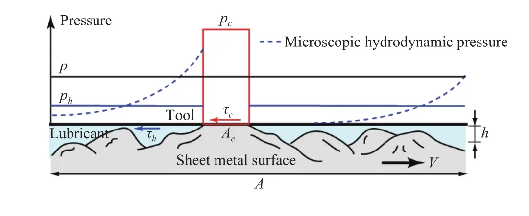
Fig. 1. Schematic representation of the lubricated contact between the tool and the sheet metal.
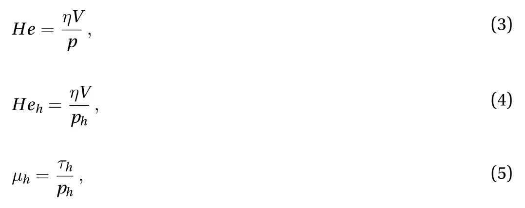
We define the Hersey parameters and the hydrodynamic coefficient of friction as
We also make the following assumptions

where Eq. (6) is Newton’s law of viscosity withhas the mean separation between the lubricated surfaces. This assumption should be seen as a measure of the mean hydrodynamic shear stress within the fluid cavities of the local scaleA. By Eq. (7), we assume that the behaviour of the hydrodynamic coefficient of friction found in hydrodynamic lubrication [1] is valid in all lubrication regimes.
The most important consequences of Eqs. (3)–(7) are
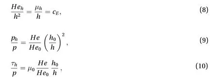
wherecE≈ 1×10³m-1is Emmens constant [1].andare respectively the Hersey parameter and the hydrodynamic coefficient of friction at the separationh0(the peak height of the surface roughness).
We define

We assume purely plastic real contacts based on the assumptions

whereHsis the surface hardness andthe Abbott–Firestone curve of the sheet metal surface. The assumption of purely plastic real contacts is commonly applied for rough contacts between a soft and a hard surface. This means that the asperities of the soft surface will deform plastically at some pressure, here called the surface hardnessHs. The actual value of this hardness may depend on sliding speed, temperature, and deformation(strain hardening), which ultimately are given by experiments.The Abbot–Firestone curve describes the material distribution along a coordinate normal to the surface. Equation (14) is the simplest approximation to the upper half of the Abbott–Firestone curve valid for a typical sheet metal. The tool surface is assumed to be rigid and flat. During plastic flattening of the roughness the displaced material is forced to flow in some way. Equation (15) is found assuming that the displaced volume fills the fluid cavity according to Fig. 2.
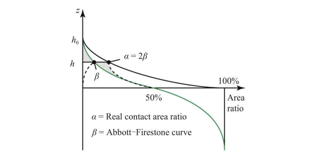
Fig. 2. The real contact area determined by mirror imaging volume displacements against the separation line h.
The most important consequences of Eqs. (11)–(15) are
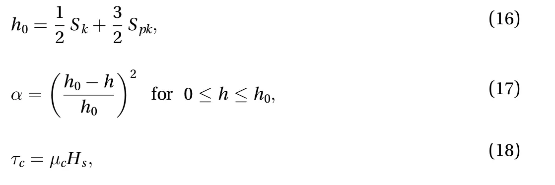
where the statistical surface parametersSkandSpkare the core roughness depth and the reduced summit height, respectively.
The normal load balance Eq. (1) can now be written in the dimensionless form

using Eqs. (9), (11), (13), and (17). This equation estimates the plastic flattening for different load conditions. The only realistic solution to this cubic equation is given by
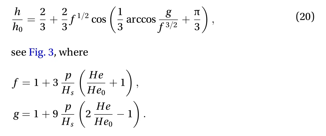
Non-dimensionalizing Eq. (2) using Eqs. (10), (11), (17), and(18), the local coefficient of friction is given by


Pure hydrodynamic lubrication rarely appears in sheet metal forming and is assumed to have a negligible effect. The model is therefore completed setting

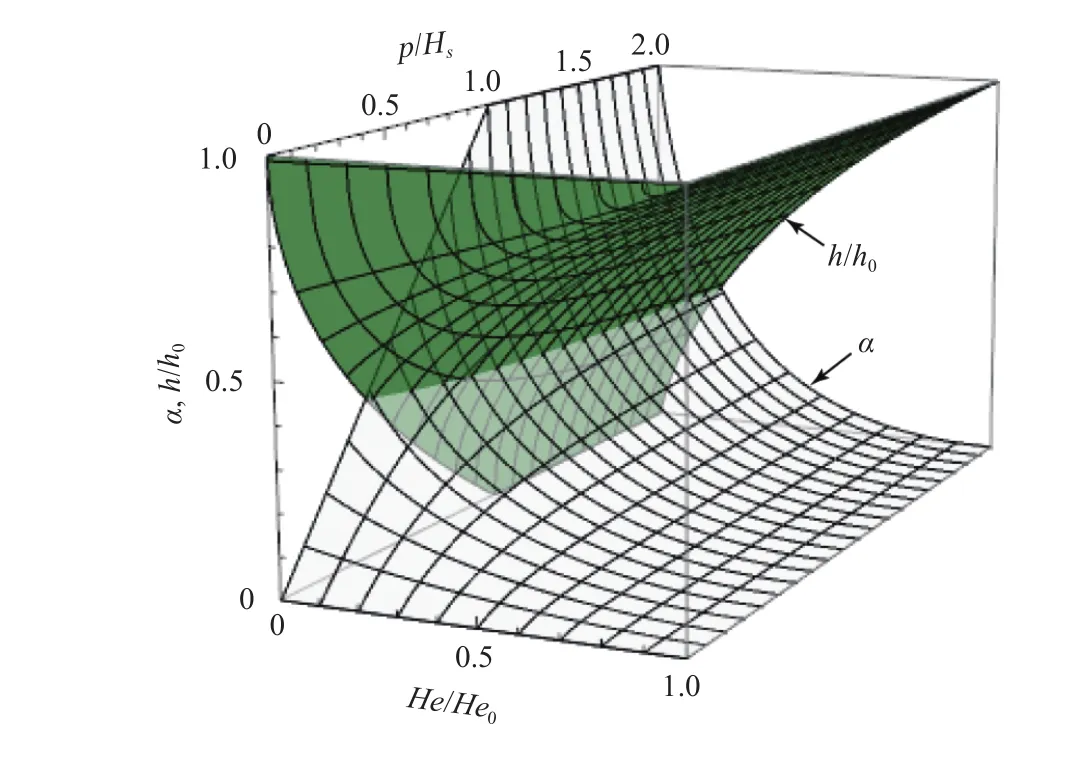
Fig. 3. A plot of the real contact area ratio α (Eq. (17)) and the dimensionless separation h/h0 (Eq. (20)).
This constitutes the end of our derivation of the local friction model, which is found to be a function of onlyc,p/Hs, andHe/He0, see Fig. 4. No restrictions are here made on the real contact coefficient of frictionc, the surface hardnessHsnor the dynamic viscosity. Instead of choosing constant values, second order effects may therefore be introduced freely.
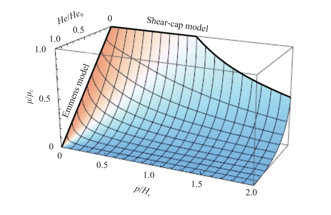
Fig. 4. The friction model (Eq. (22)). The shape of this graph is independent of second order effects in , Hs, and.
It is interesting to note (Fig. 4) that the model coincides with Emmens [1] friction model for mixed lubrication

and approaches the widely used shear-cap friction model [4] for boundary lubrication

The model can therefore be seen as a generalization of the two.
All friction experiments have some kind of pressure distribution connected to them and many suffer from edge effects. Edge effects are high pressure spikes distributed along the edges of the contact that may carry a large portion of the load. If so, the mean pressure loses its meaning as a unique parameter coupled to the friction other than for that specific contact alone. This is a serious drawback when studying the general friction behavior of nominally flat contacts and the root of much confusion when trying to interpret results [10].
In order to verify the friction model (Eq. (22)) against published experimental data, not knowing the underlying pressure distribution, comparisons are here made assuming both a uniform and a "rigid punch" pressure distribution. The rigid punch is a pressure distribution with well defined edge effects given by [11]

The global coefficient of friction is defined by

Comparing the global coefficient of friction Eq. (25) with experiments shows reasonable agreements at both high and low loads assuming constant values ofc,Hs, and, see Figs. 6 and 7.The surface hardness used in this analysis is found to be approximately equal to about 7% of the micro-Vickers hardness of the sheet metal.
The shape of the dashed curve in Fig. 6 is produced entirely due to the edge effects of the rigid punch. Friction models that explain this curve from a uniform pressure perspective will ultimately underestimate the friction stresses when it comes to forming simulations. In forming simulations, the local pressures are close to uniform and far from having edge effects if the calculation cells are not too coarse.
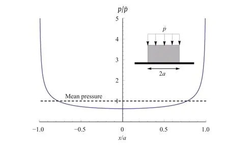
Fig. 5. The rigid punch pressure distribution.
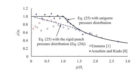
Fig. 6. The global coefficient of friction vs. flat tool sheet experiments [1, 8] in the limit of for aluminum. Assumptions:Hs = 45 MPa.
Edge effects are also evident at low loads in the measurements made by Emmens [1] in the mixed lubrication regime(Fig. 7). The close agreements with the rigid punch pressure approximation could explain why the mixed region is extended into what should be considered the region of hydrodynamic lubrication.
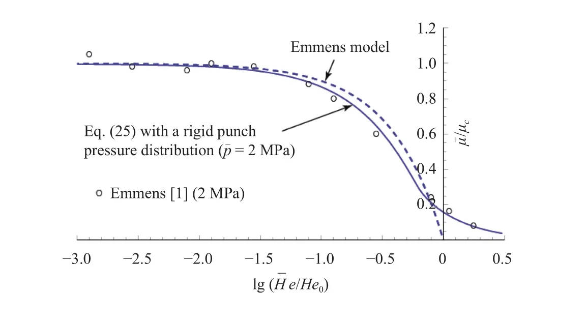
Fig. 7. The global coefficient of friction vs. flat tool sheet experiment [1] at low relative pressures= 0.02 for uncoated steel. Assumptions: = 55 MPa·s, He0 = 2×10⁻⁸ m, and Hs = 100 MPa.
This paper presents a first order friction model for sheet metal forming that can be seen as a generalization of Emmens [1]and the shear-cap model [4]. The simplicity of the model due to its restricted number of parameters makes it useful in early tool design simulations. It is derived without restrictions on the variables involved which ultimately opens up a possibility for the introduction of second order effects like strain hardening and surface anisotropy.
Finally, the importance of pressure distributions is pointed out. If experiments are not performed with close to uniform pressure distributions the results cannot directly be used for studying general friction behavior of flat contacts. Nor can any strict conclusions be made for the development of friction models.
Acknowledgements
The author wish to acknowledge Prof. B.G. Rosén, Dr. Zlate Dimkovski, and Dr. Thomas Borrvall for fruitful discussions. This research is supported by the Swedish Foundation for Strategic Research (PV08-0041).
[1]W.C. Emmens, Tribology of flat contacts and its application in deep drawing, [PhD Thesis], University of Twente, Netherlands,1997.
[2]J. Hol, M.V. Cid Alfaro, M.B. de Rooij, et al., Advanced friction modeling for sheet metal forming, Wear 286-287 (2012) 66–78.
[3]A. Westeneng, Modelling of contact anf friction in deep drawing processes, [PhD Thesis], University of Twente, Netherlands,2001.
[4]B.P. Gearing, H.S. Moon, L. Anand, A plasticity model for interface friction: application to sheet metal forming, International Journal of Plasticity 17 (2001) 237–271.
[5]I. Nogueira, A.M. Dias, R. Gras, et al., An experimental model for mixed friction during running-in, Wear 253 (2002) 541–549.
[6]D. Wiklund, B.G. Rosén, A. Wihlborg, A friction model evaluated with results from bending-under-tension, Tribology International 42 (2008) 1448–1452.
[7]M. Ramezani, Z.M. Ripin, R. Ahmad, Modelling of kinetic friction in V-bend of ultra-high-strength steel sheets, Int. J. Adv.Manuf. Technol 46 (2010) 101–110.
[8]A. Azushima, H. Kudo, Direct observation of contact behaviour to interpret the pressure dependence of the coefficient of friction in sheet metal forming, Annals of the CIRP 44 (1995)209–212.
[9]L. Figueiredo, A. Ramalho, M.C. Oliveira, et al., Experimental study of friction in sheet metal forming, Wear 271 (2011)1651–1657.
[10]M.C. Oliveira, J.L. Alves, L.F. Menezes, et al., Finite element analysis of the Amontons–Coulomb's model using local and global friction tests, in: AIP Conf. Proc 1353 (2011) 1812–1817.
[11]K.L. Johnson, Contact Mechanics, Cambridge University Press,UK, 1985.
杂志排行
Theoretical & Applied Mechanics Letters的其它文章
- Mechanical properties evaluation for thin film/substrate material systems
- Interfacial toughness evaluation of thermal barrier coatings by bending test
- A new spallation mechanism of thermal barrier coatings on aero-engine turbine blades
- Fabrication of high temperature grating on thermal barrier coatings based on solute-solvent separation soft lithography
- Microstructure design to improve the efficiency of thermal barrier coatings
- The interface of SiO2/ZnS films studied by high resolution X-ray photoluminescence
