Microstructure design to improve the efficiency of thermal barrier coatings
2018-04-10YanyanYinRuiQiHongyeZhangShangbinXiYingbinZhuZhanweiLiu
Yanyan Yin, Rui Qi, Hongye Zhang, Shangbin Xi, Yingbin Zhu, Zhanwei Liu*
School of Aerospace Engineering, Beijing Institute of Technology, Beijing 100081, China
Thermal barrier coatings (TBCs), with low thermal conductivity and very low temperature sensitivity, are initially and widely used in turbine blades of aeronautical aircraft [1-3]. Currently,they are widely used in many industry areas, where part of the working component operates in an extremely high temperature environment [4-7]. For example, the sprayed layer of ceramic TBCs on the equipment of high-temperature corrosion parts in the petrochemical industry, can significantly improve the service life of the equipment [8, 9]. The temperature of the reaction zone in the oxidation furnace is far beyond the melting point of the alloy [10]. The sprayed TBCs on the heat-resistant alloy can dramatically help improve the ability of high temperature resistant for the alloy structure [11, 12].
Increasing the thrust-to-weight ratio is one of the main research directions of the aircraft engine. To achieve this, the inlet temperature of the engine turbine needs to be increased, and it is believed that the inlet temperature will reach 1930°C soon [12-14]. Such a high operating temperature is far beyond the operating temperature of the current existing super-alloy [15]. Therefore, to meet the higher engine inlet temperature requirement,seeking new material or structure is an important direction for the fabrication and development of TBCs. To obtain an ideal TBCs structure, one of the promising directions is to design a TBCs structure with lower thermal conductivity.
Recent studies have shown that the rare earth zirconates is one of the most promising surface ceramic material in TBCs, owing to its good thermal physical properties, like lower thermal conductivity, high coefficient of thermal expansion, and high temperature phase stability up to 2300°C [16]. Many scholars have added other chemical element into the ceramic coat to reduce the thermal conductivity and improve its phase stability[17, 18].
There are many ways to obtain a TBCs structure with lower thermal conductivity, one of which making microstructure on the TBCs structure is considered to be a possible and important way. Scholars have put forward this new method to enhance the thermal performance of ceramics through fabricating nanostructure into the ceramic [19]. The proposed new method can help the insensitive ceramics withstand thermal shocks until its melting temperature, in which there is nano-structure on the ceramic surface. When the structure is heated and heat conduction occurs, the temperature drops rapidly near the nano-structure, indicating nano-structure has a good insulation effect.
In this study, a TBCs structure with lower thermal conductivity and enhanced thermal insulation effect was obtained through fabricating the designed microstructure in the substrate or bonding coat and filling hollow ceramic microspheres into the interspace. The size parameters of the designed microstructure were optimized. Compared with the traditional TBCs structure without microstructure, the designed microstructure can significantly improve the insulation temperature of more than 110°C and the thermal balance time have a big improvement of 240 s,more than 50% of the balance time than that in the traditional TBCs structure.
To analyze whether microstructure in the thermal barrier coatings has thermal insulation, the structure model was firstly simplified into a two-layer structure, where the ceramic coating is directly sprayed on the substrate for simulation analysis.Through finite element analysis (FEA), the insulation effect of the designed microstructure, where the column-like microstructure array was fabricated on the substrate surface and the hollow ceramic microspheres was filled in the interspace, was analyzed. Filling the hollow ceramic microspheres in the microstructure gap is to prevent the ceramic from penetrating the microstructure in the gap when spraying the ceramic layer. The hollow ceramic microsphere was selected because of its high compressive strength, low thermal conductivity, high melting point, chemical stability and so on [20]. The two-layer structures consist of the Nickel-based super-alloy substrate and ZrO2ceramic top coat and part of their material parameters are listed in Table 1, where the material parameter of the bonding coat is also listed.
The hollow ceramic microspheres are mainly composed of TiO2, Al2O3, and SiO2[21, 22], and its material parameters are listed in Table 2.
A column-like array with rectangular cross section is designed on the upper surface of the substrate, as shown in Fig. 1.When the ceramic is sprayed on the surface of the substrate, the ceramic will penetrate into the interspace of the designed column-like microstructure. The hollow ceramic microspheres can be filled in the interspace beforehand. As a result, the contact area between the ceramic layer and the substrate is likely to be increased and the bonding strength between the two materials is also expected to be improved. However, in this study, attention is only focused on the evaluation of insulation effect for the designed microstructure, without considering the bonding strength. The height of the designed microstructure is denoted byH, the width is denoted bya, the interval is represented byb,and the height of the hollow ceramic bead is indicated byh. The thickness of the substrate is 5 mm, the thickness of the ceramic layer is 300 μm, and the specific parameters in the microstructure are shown in Table 3.
Thermal boundary condition was firstly applied to the ceramic surface of the TBCs, where the ceramic surface was set to be heated up to 1100°C in 40 s. Then the process of heat conduction was analyzed through FEA. To compare the thermal insulation effect of the designed microstructure, three concrete models, model I without microstructure, model II with established microstructure filled with hollow particles in the interspace and the model III with designed microstructure without filling any particles, were designed for FEA. The temperature field distribution after 40 s of heating is shown in Fig. 2. From the left to the right, the temperature field of model I, model II, andmodel III. Obviously, according to the isotherm distribution, we can find that the temperature field in the microstructure region is lower than the temperature field in model I, and the microstructure plays the role of delayed temperature conduction. And the model III has the best insulation effect. In our opinions, it is resulted by the interspace in the FEA model. The interspace is considered to be vacuum and it has no thermal conductivity.Owing to the interspace, the contact area between the ceramic coat and the substrate will be smaller than the model II.However, the vacuum model III is impossible to achieve. Fortunately, the designed microstructure combined with hollow particles can also effectively delay the rapid transfer of heat from the FEA result. So, model II is finally chosen in this paper for optimization and further analysis.

Table 1 Basic parameters of the TBCs material.

Table 2 Parameters of hollow ceramic microspheres.
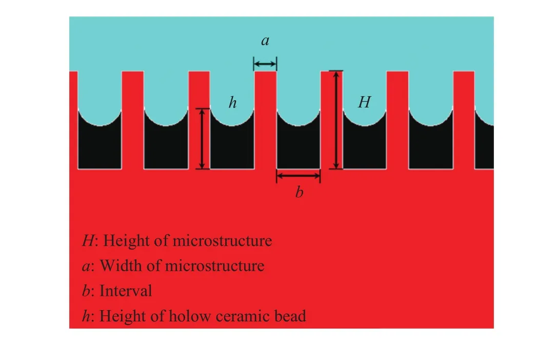
Fig. 1. Column-like microstructures designed on the surface of the substrate.
There are four parameters that can be optimized of the designed microstructure model, including the height, the width,the interval, and the height of the filled hollow particles or the penetration distance of the ceramic layer. Considering that the thickness of the ceramic layer is generally about 300 μm in a real turbine blade, the height of the microstructure cannot be set too large. After numerous simulation, the height of the microstructure is set to be 200 μm. The other parameters, includinga,b,andh, are set to 1 μm, 10 μm, 100 μm, and 1000 μm for analysis.The structure model with the four different orders of magnitude was analyzed using FEA. The insulation effect after 40 s heating is listed in Table 4, where the insulation effect is defined as the temperature difference between the surface of the ceramic coat and the base of the substrate.
For the four structure models with different orders of magnitude, the insulation effect increase with the increase of the magnitude. The increase of the thermal insulation effect of the TBCs structure with designed microstructure is resulted by the size of microstructure and the amount of hollow ceramic microspheres filled in the interspace. The larger the microstructure size there are, the better the insulation effect of TBCs structure will be. Considering the fact that the thickness of the ceramic layer in the real TBCs is generally less than 400 μm, if the size of the interval is greater than 400 μm, the ceramic coat will penetrate too much into the interspace, and the surface of the ceramic top coat will not smooth enough, which will affect the overall performance of the engine turbine blades. Besides, the substrate surface before spraying is not flat due to the shot peening process. Considering the limitations of micromachining technique,as well as the size of hollow ceramic particles and so on, the interval size of the microstructure should be greater than 10μm.Above all, the interval size of the microstructure in the order of 100 μm is much more accordance with the actual condition.

Table 3 Specific parameters of the designed microstructure (unit: μm).
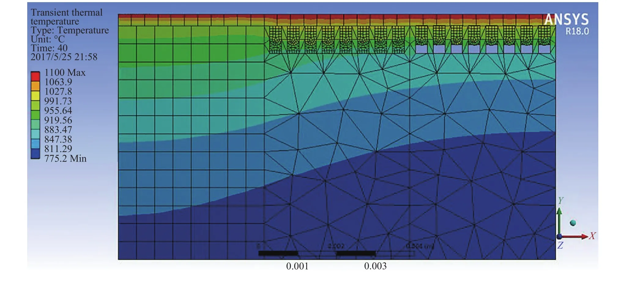
Fig. 2. The temperature field distribution of the simulation result.
In practice, there are three layers in a real TBCs structure,named ceramic layer (ZrO2ceramic top coat), bonding coat (adhesive layer), and substrate (Nickel-based supper-alloy), separately. A cuboid model is selected for simulation, which is 50×40×5 mm3. The microstructure parameters in the simulation are based on the true dimensions of the thermal barrier coating.The parameters of the model used in this study are as follows:the thickness of the ceramic layer is 300 μm, the thickness of the bonding coat is 150 μm, the thickness of the substrate is 5 mm,the height of the microstructure is 120 μm, the width of the microstructure is 125 μm, the interval is 100 μm, and the height of the filled hollow particles is 90 μm. This set of parameters, as an example, is used to analyze the thermal insulation effect of thermal barrier coatings in the case of rational design of microstructures.
To simulate the thermal insulation effect more closely to the actual condition, the heating time was extended to 1 h. Meanwhile, the thermal boundary condition was added to the lower surface of the TBCs structure (the base of the substrate), and the thermal contact resistance was also set at the interface between two different solid. The thermal boundary condition of the upper surface of the ceramic layer was defined, where the relationship between the temperature curve and heating time is shown in Fig. 3. The heating process is performed in two stages: the first stage is rapid heating to 1100°C in 0–40 s, the second stage is constant temperature heating at 1100°C in 40–3600 s.
There are air refreshing tubes in a real turbine blade for cooling through convection. The heat dissipation is related to the surrounding environment temperature, heat dissipation area,and air speed [23]. In the FEA of this section, the heat dissipation is determined by the ambient temperature and the convective heat transfer coefficient. Based on the conclusion of gas jet impact test, when the temperature is constant, the convective heat transfer coefficient increases with the increase of the air velocity, and it is in the range of 120–136 W/(m·°C) [24-26]. And according to the existing literature, the heat dissipation is set at the lower surface of the substrate. The ambient temperature is 22°C,and the convective heat transfer coefficient is set 120 W/(m·°C)here.
The heat transfer resistance, which is also called thermal contact resistance, is common between two contacted solid.Some scholars have studied the high temperature thermal contact resistance of the finite element simulation method [27]. According to the method of obtaining the heat transfer resistance,we did the simulation work in the ABAQUS software, and the thermal contact resistance analog value is 7.90°C/W, 5.60°C/W,3.85°C/W, and 4.30°C/W between the ceramic layer and the bonding coat, the bonding coat and the substrate, the bonding coat and hollow ceramic microspheres and the bonding coat and hollow ceramic microspheres, separately.
The thermal insulation effect of the TBCs with and without microstructure was simulated under the same condition, respectively. The following conclusions were obtained:
(1) The temperature field of the TBCs with and without the designed microstructure at 3600 s is shown in Fig. 4. The insulation effect of the TBCs without microstructure can insulate up to 192.00°C and the insulation effect of the TBCs with microstructure can insulate up to 304.37°C. Obviously, the designed microstructure has a vast improvement in enhancing the thermal insulation effect of the TBCs structure, with more than 110°C improvement compared with the TBCs without microstructure.
(2) The relationship of the temperature difference and the heating time is shown in Fig. 5. The temperature difference is between the upper and lower surface of the TBCs structure with and without microstructure. Heat transfer of the TBCs without microstructures achieves a balance at 460 s, meaning that the temperature distribution in the TBCs structure is stable. That of the TBCs with the designed microstructures reaches to a balance at 700 s. The thermal balance time has a big improvement of 240 s, more than 50%, than the traditional TBCs structure. Atthe beginning of the rapid heating stage, the temperature difference of the two models is almost the same. Then the temperature difference of the TBCs structure with designed microstructure become greater than the TBCs without microstructure, as well as in the following constant temperature heating stage. The temperature difference of the TBCs with designed microstructure is always higher than the TBCs without microstructure,meaning that the designed microstructure does have favorable influence in improving the thermal insulation effect of TBCs.With prolonged balance time, the thermal mismatch stress in the TBCs structure may be smaller than before and the interaction between the different layers may be slower and gentle.

Table 4 The insulation effect of the four structure models with different orders of magnitude.

Fig. 3. The heating rate calibration curve of the simulated thermal test.
In this paper, microstructures were designed on the substrate or bonding coat of TBCs to study the thermal insulation effect. The size parameters of the designed microstructure were optimized. The thermal insulation temperature of the TBCs model with and without microstructure was compared in the two-layer model and real TBCs structure model. It is found that the designed microstructure, filled with hollow ceramic microspheres in the interspace, on the substrate or the bonding coat can effectively reduce the thermal conductivity of the TBCs and improve the thermal insulation effect. The existence of the designed microstructure can significantly prolong the thermal balance time of TBCs, with more than 50% balance time than the traditional TBCs structure, and the insulation temperature can exceed 300°C. Compared with the TBCs structure without micro-structure, the designed microstructure can significantly improve the insulation temperature of more than 110°C.
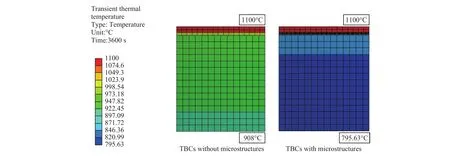
Fig. 4. Temperature field of the simulated TBCs structure without and with designed microstructure at 3600 s.
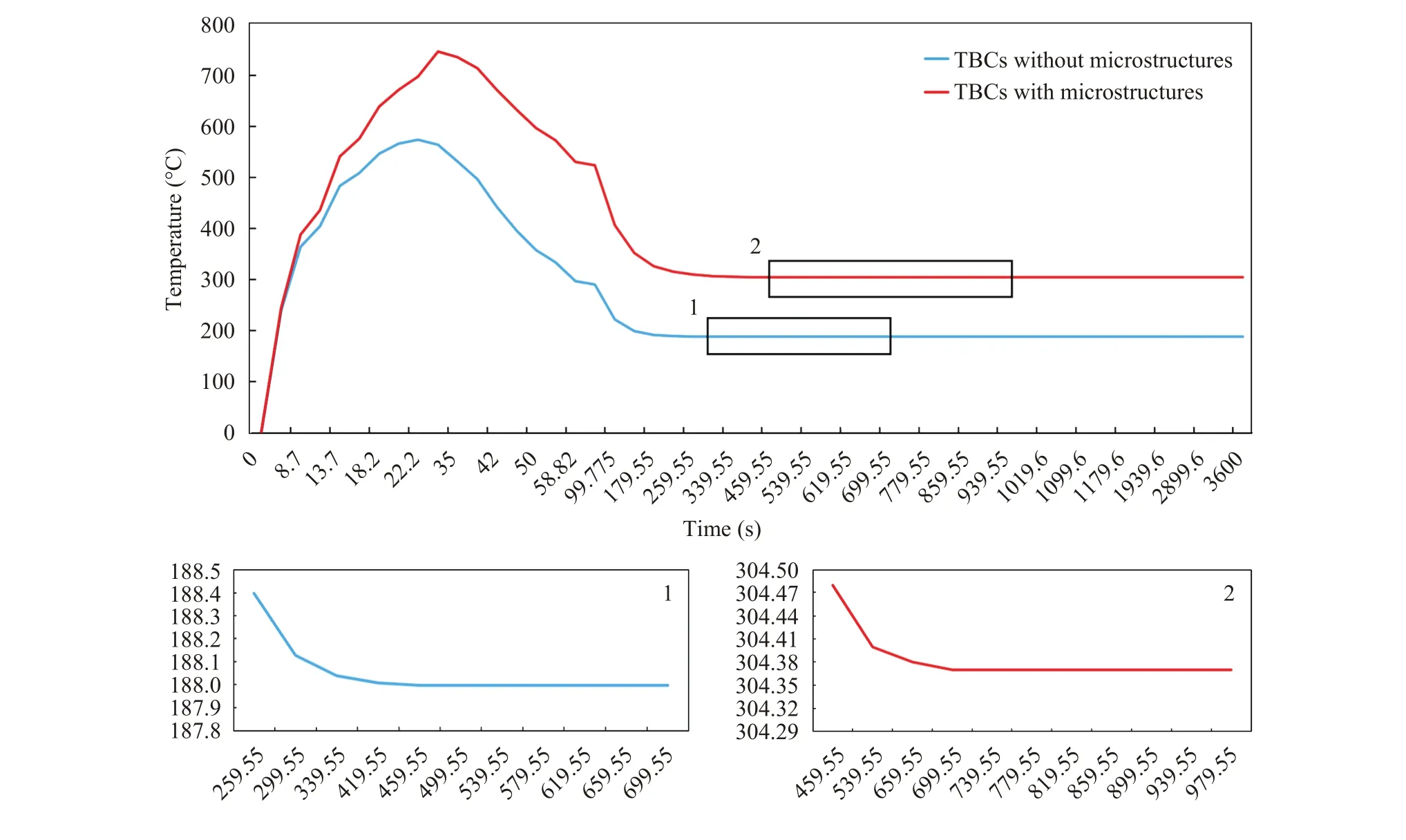
Fig. 5. Relationship of the heating time and the temperature difference between the upper and lower surfaces of the TBCs with and without microstructure.
Acknowledgements
This work was financially supported by the National Natural Science Foundation of China (11372037, 11572041, and 11232008).
[1]N.P. Padture, M. Gell, E.H. Jordan, Thermal barrier coatings for gas-turbine engine applications, Science 296 (2002) 280–284.
[2]L. Lorenzoni, S. Ahmaniemi, Studies of the sintering kinetics of thick thermal barrier coatings by thermal diffusivity measurements, Journal of the European Ceramic Society 25 (2005)393–400.
[3]C.X. Zhang, C.G. Zhou, H. Peng, et al., Influence of thermal shock on insulation effect of nano-multilayer thermal barrier coatings, Surface & Coatings Technology 201 (2007) 6340–6344.
[4]C. Ren, Y.D. He, D.R. Wang, Preparation and characteristics of three-layer YSZ-(YSZ/Al2O3)-YSZ TBCs, Applied Surface Science 257 (2011) 6837–6842.
[5]V. Lughi, V.K. Tolpygo, D.R. Clarke, Microstructural aspects of the sintering of thermal barrier coatings, Materials Science &Engineering A 368 (2004) 212–221.
[6]R. Dutton, R. Wheeler, K.S. Ravichandran, et al., Effect of heat treatment on the thermal conductivity of plasma-sprayed thermal barrier coatings, Journal of Thermal Spray Technology 9 (2000) 204–209.
[7]J.G. Zhu, H.M. Xie, Y.J. Li, et al., Interfacial residual stress analysis of thermal spray coatings by miniature ring-core cutting combined with DIC method, Experimental Mechanics 54(2014) 127–136.
[8]T. Lv, Application of ceramic thermal barrier coating in petrochemical industry, Journal of Beijing Institute of Petro-Chemical Technology 15 (2007) 17–21.
[9]J.G. Zhu, W. Chen, H.M. Xie, Simulation of residual stresses and their effects on thermal barrier coating systems using finite element method, Science China Physics Mechanics & Astronomy 58 (2015) 1–10.
[10]B. Goswami, S.K. Sahay, A.K. Ray, Application of thermal barrier coatings on combustion chamber liners—A review, High Temperature Materials & Processes 23 (2004) 211–236.
[11]D. Marcin, T. Jeanine, D.K. Gupta, Protective coatings in the gas turbine engine, Surface & Coatings Technologys 68 (1994) 1–9.
[12]Q. Xue, Application of rare earths in thermal barrier coating materials, Materials Science and Technology 23 (2007) 15–35.
[13]X.Y. Xie, H.B. Guo, S.K. Gong, Mechanical properties of LaTi2Al9O19, and thermal cycling behaviors of plasma-sprayed LaTi2Al9O19/YSZ thermal barrier coatings, Journal of Thermal Spray Technology 19 (2010) 1179–1185.
[14]X.Y. Xie, H.B. Guo, S.K. Gong, et al., Lanthanum–titanium–aluminum oxide: A novel thermal barrier coating material for applications at 1300°C, Journal of the European Ceramic Society 31 (2011) 1677–1683.
[15]K. Ma, J.G. Zhu, H.M. Xie, et al., Effect of porous microstructure on the elastic modulus of plasma-sprayed thermal barrier coatings: Experiment and numerical analysis, Surface & Coatings Technology 235 (2013) 589–595.
[16]S.S. Yang, X.G. Chen, Methods of increasing thermal insulation property of plasma-spraying thermal barrier coatings, Foundry Technology 33 (2012) 677–679.
[17]H.M. Zhou, D.Q. Yi, Effect of rare earth doping on thermo-physical properties of lanthanum zirconate ceramic for thermal barrier coatings, Journal of Rare Earths 26 (2008) 770–774.
[18]W. Ma, F.Y. Song, H.Y. Dong, et al., Thermophysical properties of Y2O3and Gd2O3Co―doped SrZrO3thermal barrier coating material, Journal of Inorganic Materials 27 (2012) 209–213.
[19]F. Song, S. Meng, X. Xu, et al., Enhanced thermal shock resistance of ceramics through biomimetically inspired nanofins,Physical Review Letters 104 (2010) 1–4.
[20]Z. Zhong, Y. Yin, B. Gates, et al., Preparation of mesoscale hollow spheres of TiO2and SnO2by templating against crystalline arrays of polystyrene beads, Advanced Materials 12 (2000)206–209.
[21]Y.W. Bao, D.Y. Jiang, L. Tian, et al., Synthesis and electromagnetic properties of hollow ceramic microspheres, Key Engineering Materials 492 (2012) 260–263.
[22]L. Liu, B.C. Xu, Preparing and characterization of hollow ceramic microspheres, Key Engineering Materials 1809 (2012)245–248.
[23]H. He, W.Q. Liu, Analytical temperature of high speed gas ejection pipe under natural convection heat transfer to air, Industrial Heating 37 (2008) 19–22.
[24]D. Spierings, F. Bosman, T. Peters, et al., Determination of the convective heat transfer coefficient, Dental Materials 3 (1987)161–164.
[25]Y. Nishi, Direct evaluation of the convective heat transfer coefficient for various activities and environment, Arch. Sci. Physiol.27 (1973) 59–66.
[26]H. Du, D.Z. Lu, J.Z. Qi, et al., Heat dissipation performance of porous copper with elongated cylindrical pores, Journal of Materials Science & Technology 30 (2014) 934–938.
[27]D.H. Liu, F. Wang, F.W. Zeng, et al., Finite element simulation method of high temperature thermal contact resistance, Engineering Mechanics 29 (2012) 375–379.
杂志排行
Theoretical & Applied Mechanics Letters的其它文章
- Mechanical properties evaluation for thin film/substrate material systems
- Interfacial toughness evaluation of thermal barrier coatings by bending test
- A new spallation mechanism of thermal barrier coatings on aero-engine turbine blades
- Fabrication of high temperature grating on thermal barrier coatings based on solute-solvent separation soft lithography
- The interface of SiO2/ZnS films studied by high resolution X-ray photoluminescence
- Threshold characteristics of short-pulsed loads combined with the ultrasound field causing dynamic delamination of adhesive joints
