Large Waterway-crossing Immersed Tunnel for Highway andRailway Transportation: Dongping Tunnel in Foshan, China
2018-03-27HEWeiguoLYUYangSONGChaoye
HE Weiguo, LYU Yang, SONG Chaoye
(China Railway Tunnel Survey and Design Institute Co., Ltd., Tianjin 300133, China)
1 Significance of Dongping Tunnel
Dongping Tunnel is an important passage in the Pearl River Delta Region. It not only enables fast collection and distribution of passenger flow and material flow, but also drives development of the central cities in the whole Pearl River Delta Economic Zone and enhances the region′s ability for economic agglomeration. Thus, it allows the strategic southward expansion of Guangzhou City.
For the development of Guangdong-Hong Kong-Macao Great Bay area, this tunnel becomes an important part of the closed fast road network that connects the Shenzhen-Hong Kong Economic Zone, Guangzhou-Foshan Economic Zone and Zhuhai-Macao Economic Zone. It can further integrate the cities on the west bank of the Pearl River Mouth, which are supported by manufacturing industry, with Hong Kong and Macao. Such integration of the Pearl River Delta Region will herald a new stage of development.
2 General description of Dongping Tunnel
Dongping Tunnel, as a key construction project in Foshan City, connects the old urban region of Chancheng and new urban area of Foshan. The whde line is 2 410 m long, including the 1380 m long tunnel. The river-crossing tunnel, which is constructed with immersed tube method, serves for both urban road and Guangzhou-Foshan Metro. The tunnel is the immersed tunnel built in China that has the largest cross-section and serves for highway and metro. The cross-section of the immersed tunnel is asymmetric in structure, having three tubes and one gallery. The size of the cross-section is 39.9 m × 9 m. The length of each immersed tube is 115 m long. Each immersed tube weighs approximately 50 000 tonnes.
The plane view of Dongping Tunnel is shown in Fig. 1, and the cross-section of Dongping Tunnel is shown in Fig. 2. The main technological parameters of the urban road and the metro are listed in Table 1 and Table 2 respectively.

Fig. 1 Plane view of Dongping Tunnel
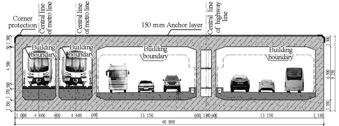
Fig. 2 Cross-section of Dongping Tunnel (unit: mm)

HighwaylevelDesignedvehiclespeed/(km/h)Widthoftrafficlane/mHeightlimit/mRoadsurfaceMaximumlongitudinalgradient/%Designedservicelife/yearGradeⅠurbanroad502×3.5+3.754.5Asphaltconcrete4.5100

Table 2 Main technological parameters of metro
3 Surrounding environment and geologic characteristics
3.1 Hydrological characteristics of the river
The project is located at Dongping Waterway, Which is at the middle and upper reaches of the river, and there are irregular half-day mixed tides. The waterway experiences motions with the rise and fall of tides. During flood period, the maximum water flow rate is higher than 2-3 m/s; while in dry season, the maximum water flow rate is approximately 1.0 m/s.
3.2 Navigation channel and navigation condition
This tunnel is located at the bent section of the waterway. At present, the water surface of the waterway is about 250 m wide, and the waterway is planned as Grade Ⅱ navigation channel (Fig. 3).The actual water depth is 4-13 m and the width of the navigation channel ranges from 60 m to 80 m. The bending radius of the navigation channel is 400 m. The navigation channel can accommodate 1 000 tonnes of fleet. As a golden navigation channel of Guangdong Province, Dongping navigation channel receives 300 ships/h during peak hours.

Fig. 3 Planned navigation channel of Dongping Waterway
3.3 Current situation and planning of flood control
The north bank of Dongping waterway is Foshan Bank, with Grade Ⅱ flood control level. The south bank of Dongping Waterway is Nanshun Second Lianwei Bank, with Grade Ⅲ flood control level. The flood control standard is designed for a great flood event of every 50 years. The elevation of the top of north Foshan Bank where the tunnel is located is 8.0 m, and the elevation of the ground surface behind Foshan Bank is about 5.5 m. The elevation of the top of Nanshun Second Lianwei Bank is 8.5 m, and the elevation of the ground surface behind Nanshun Second Lianwei Bank is 3.5-5.0 m. Thus forms a typical "aboveground river". The flood control requirements are relatively high.
3.4 Geologic features
The geological profile of cross-river section of Dongping Tunnel is shown in Fig. 4. The geological condition underwater is dominated by intensely-weathered mudstones and intermediately-weathered sandstones. Underwater blasting is needed before excavation. The total excavation volume of underwater foundation trench is 429 000 m3, including 335 000 m3underwater blasting (78%).
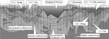
Fig. 4 Geological profile of cross-river tunnel section
4 Key features of the project
The project is located in the downtown area of Foshan City, with complicated surroundings. The key features of the project include:
(1)The watercourse has an S-shaped bend, and with high water flow rate, seriously scoured river-bed, interlaced strata with uneven strengths in the bed and exposed rocks in some sections and the geological and hydrological conditions are very complicated.
(2)The location has intensive ship passage. It is an inland waterway with maximum navigation density in China.
(3)There are many ports, wharfs and water gates in surrounding areas, and there are dense old buildings on both banks.
(4)The elevation of the banks is 3.2 m higher than that of the main urban area, and a typical "aboveground river" is formed. The flood control requirements are extremely high.
(5)The construction standards for the highway are greatly different from those for the metro. There are great difficulties in the structural design of the tunnel. There are strict requirements on the settlement of the metro.
5 Main technological innovations
A total of 11 key technologies have been studied in the design of the project, and 15 patient licenses have been won.
5.1 Design for asymmetric cross-section of road-rail tunnel structure at the immersed section
The immersed tunnel has twin tubes and one gallery tube for the highway, as well as twin tubes for the metro (the separation wall is installed at the later stage). Levelling layer on the floor and ballast water tanks are used innovatively to ensure the balance of the element tube of the tunnel during floating, transporting and sinking realtimely. Real-time balance keeping design of the element tube is shown in Fig. 5.

(a) Cross-section showing arrangement of ballast water tanks

(b) Cross-section showing arrangement of ballast concrete and internal structural layout
5.2 Dock on one side of the tunnel
Dry dock on one side of the tunnel is proposed innovatively (Fig. 6). The dry dock and the main on-shore structure of the tunnel share the same foundation pit while the fabrication of the immersed tubes is separated from the main on-shore structure of the tunnel. In this way, on the one hand, the construction of the main on-shore structure of the tunnel and the fabrication of the immersed tubes can be carried out in parallel, and on the other hand, the cost of the project is reduced. Compared to independent dry dock, this design scheme saves 18 000 m2temporary land occupation and 6 million RMB yuan investment. Compared to the scheme of axial dry dock, this design scheme reduces the construction period by 8 months.
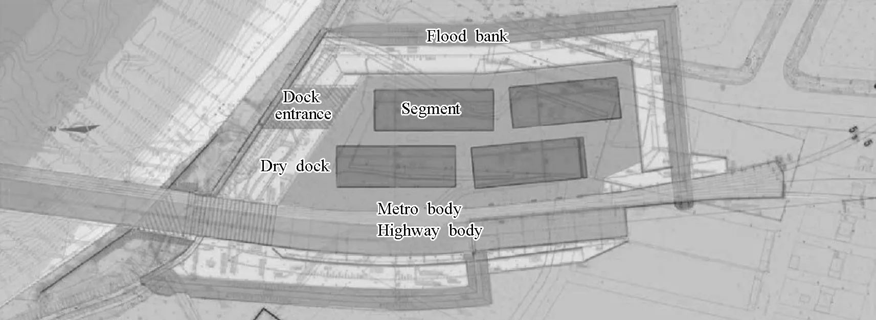
Fig. 6 Design scheme for side dry dock
5.3 Fast floating transportation and immersion under high water flow rate
Since the tunnel is located at the S-shaped bend position at the midstream of the inland river, the maximum water flow rate of the river is higher than 3 m/s, with very complicated water flow directions. In one month, there are at most 2 days suitable for the floating transportation of the element tubes (window time).Many patent technologies have been developed so that the floating transportation and sinking of the element tubes can be carried out in the short time duration, which in turn ensures the construction period of the tunnel.
5.4 Reducing load by installing prefabricated caissons and joint settlement control technology
Due to the restriction of waterway planning and the condition of present trench, the overburden of the tunnel structure on-shore reaches 17 m. The net span of the traffic tunnel is 12.65 m. Prefabricated caissons are proposed innovatively (Fig. 7) to reduce the load on the on-shore tunnel structure.

(a) Longitudinal profile showing arrangement of caissons (b) Hoisting of caisson
Fig. 7 Design of caissons to reduce load
In order to control the differential settlement of the rube joints onshore, the following two additional measures are taken:
(1) Cantilever slab combining shaped steel and concrete (Fig. 8) is adopted innovatively to replace the conventional horizontal shearing key so that the element tubes are free in the vertical direction and undertake shear force in horizontal direction.

(a) Profile of combined joint structure (b) Photos of combined joint structure
Fig. 8 Design of steel-reinforced concrete combined with cantilever slab
(2) The steel plates are processed into W-shape by cold machining. Both ends of the steel plate are connected to the element tube and the side wall of the on-shore structure respectively by means of embedded anchors (Fig. 9), so that the element tube is free in the longitudinal direction and is restricted in the vertical direction.

(a) Site installation (b) Completion
Fig. 9 Site installation of W-shaped steel plates
5.5 Protecting element tubes against erosion
The water flow rate of Dongping Waterway is high and the river bed is scoured seriously. Through theoretical analysis and physical modelling, the hydrological flexible rowed blocks are adopted (Fig. 10) to protect the immersed tunnel from damage caused by long-term scouring.
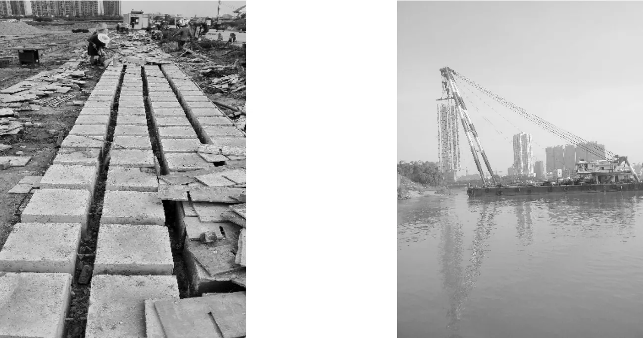
(a) Site prefabrication (b) Site installation
Fig. 10 Prefabrication and installation of flexible rowed blocks
5.6 Underwater blasting and vibration-reducing technology
Due to the high elevation of the rock surface, 335 000 m3rocks need to be excavated by means of underwater blasting. Comprehensive blasting technology consisting of milli-second blasting, air bubble curtain and steel sealing door vibration monitoring (Fig. 11) is proposed, which not only ensures the safety of the immersed tubes, but also meets the environmental protection requirements of the downtown area.
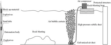
Fig. 11 Diagram of underwater blasting and vibration-reducing technology
5.7 Nondestructive testing of sand filling foundation
Non-destructive testing of the sand filling foundations is achieved for the first time (Fig. 12), which provides basis for the accurate prediction of the post-construction settlement.
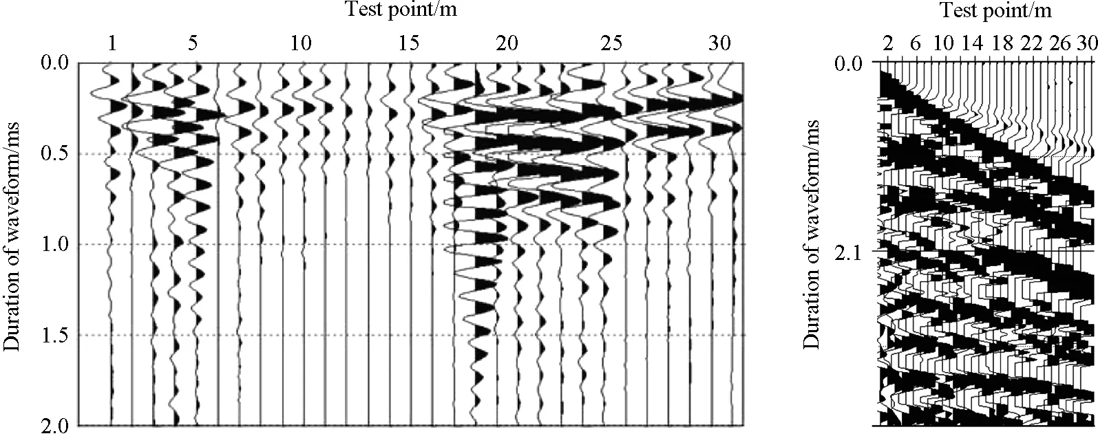
(a) Waveform records of elastic wave mapping method (b) Waveform records of Rayleigh wave method

(c) Layering effect achieved by high-frequency surface wave based on measuring line
6 Project schedule
The project was started on November 19, 2010, and the tunnel was opened to traffic on January 22, 2017. The total construction period was 74 months. Excluding the period for site demolition and change of the channel (24 months), the normal construction period was approximately 50 months.
7 Project participants
Owner: Foshan New City Development and Construction Co., Ltd.
Survey and Design Institute: China Railway Tunnel Survey and Design Institute Co., Ltd.
Construction Contractors: Guangzhou Salvage Bureau of Ministry of Transport, CCCC Fourth Harbour Engineering Co., Ltd. and Guangdong Yuantian Engineering Co., Ltd.
Supervisors: Haike (Group) Co., Ltd of Shanghai Jiaotong University and Foshan Dezheng City Construction Engineering Supervision Co., Ltd.
8 Photos of Dongping tunnel
The photos of Dongping Tunnel are shown in Fig. 13 to Fig. 25.

(a) North portal of Dongping Tunnel (b) South portal of Dongping Tunnel
Fig. 13 Photos of portals of Dongping Tunnel

Fig. 14 Casting concrete for main structure of Dongping Tunnel Fig. 15 Binding steel bar for main structure of Dongping Tunnel

Fig. 16 Installing steel door and steel shear key for Dongping Tunnel Fig. 17 Installing GINA water stop for Dongping Tunnel

Fig. 18 GINA water stop protection and steel door of Dongping Tunnel Fig. 19 Completed main structure of Dongping Tunnel

Fig. 20 Leakage test of dry dock of Dongping Tunnel Fig. 21 Removal of steel pipe piles at the end of Dongping Tunnel

Fig. 22 Floating transportation of element tube of Dongping Tunnel Fig. 23 Installation of formwork for the final joint of Dongping Tunnel

Fig. 24 Backfilling of cover layer on Dongping Tunnel Fig. 25 Interior decoration of Dongping Tunnel
