Distortion performance of underwater acoustic mobile networks Andrej Stefanov
2018-03-14
Abstract The paper considers the distortion performance of mobile underwater acoustic networks. The network is composed of autonomous underwater vehicles (AUV's) that utilize multihop transmissions to route the information through the network. The mobility model is direction persistent. The distortion is evaluated in the context of an independent identically distributed (i.i.d.) Gaussian source and single description coding. Each AUV-to-AUV channel experiences frequency dependent path loss and Ricean fading, as well as interference from other network transmissions. Numerical examples illustrate the distortion performance.
1.Introduction
There have recently been a number of studies of underwater acoustic networks [1-5] . The analysis, design and evaluation of multiaccess protocols for underwater acoustic networks has been considered in [6,7] . An energy efficient multiaccess protocol for bursty data has been proposed in [8] ,while the throughput efficiency of linear networks has been considered in [9] . Routing for linear networks that takes into consideration frequency selection and relay locations has been studied in [10] . Localization based routing has been the focus of [11] . A survey of routing related issues and protocols can be found in [12] .
These studies have been motivated in part by the need to perform sensing and surveying of underwater areas for a variety of reasons, including environmental, scientific, commercial, etc. The potential applications are numerous, e.g.,general oceanographic needs, observations of marine biology and/or fisheries [13] , environmental (pollution) monitoring [14] , monitoring of off shore oil and gas fields, submarine detection etc. Networks consisting of AUV's that offer mobility may represent a particularly appealing choice in this regard [15] .
The seamless operation of mobile underwater acoustic networks relies on the coordination and localization of AUV's.Robust distributed localization of AUV's solely from noisy range measurements has been the focus of [16] . Localization with motion compensation has been studied in [17] . Long range localization has been addressed in [18] . Coordination and navigation of AUV's has been investigated in [19,20] .Results for AUV obstacle avoidance approaches have been reported in [21] . A review of AUV navigation and localization related issues can be found in [22] .
Considering the sensing related tasks, that in addition to sensing, include computing, transmission, and reception, it is transmission that imposes the most significant strain on the energy consumption. In underwater acoustic communications,the attenuation (path loss) experienced by the transmitted signal depends not only on the transmitter-receiver distance,but also on the carrier operating frequency. The appropriate choice of the carrier operating frequency is crucial for efficient underwater communications. In addition, as underwater communication is facilitated by transmission of acoustic signals, the low speed at which sound propagates underwater results in significant transmission delays. The underwater communication channel is commonly described by the frequency selective fading model.

Fig. 1. The absorption coefficient a( f) given in dB/km for the signal frequency f in kHz: 10 log a(f ) = + 0.0 03 [24] .
The paper considers the distortion performance of mobile underwater acoustic networks. An i.i.d. Gaussian source and a single description coder are considered. The focus is on the evaluation of the end-to-end distortion across a multihop route of AUV's. Each AUV-to-AUV link experiences frequency dependent path loss and independent Ricean fading.AUV's forward the packets using simple demodulate and forward relaying. The mobility model is direction persistent [23] . The multihop routing is facilitated by a modified version of the reserve listen and go transmission protocol.The modification is based on the introduction of a request of request to send (RTS) and clear to send (CTS) messages before the transmission phase, in order to alleviate the impact of interference from other network transmissions.
The organization of the paper is as follows. The model for underwater acoustic propagation is outlined in Section 2. The distortion performance of a multihop route across the mobile underwater acoustic network is considered in Section 3,which also describes the mobility model and the transmission protocol. Section 4 illustrates the distortion performance of the mobile underwater acoustic network through numerical examples. Conclusion is given in Section 5.
2.Underwater acoustic propagation
Underwater acoustic communication experiences attenuation, i.e., path loss, for a signal transmitted on frequencyf,that is characterized by,A(d,f) =A0dκa(f)d, whereA0is a unit-normalization constant that incorporates fixed losses,dis the distance between AUV's, κis the spreading factor(1 ≤ κ ≤2), anda(f) is the absorption coefficient, illustrated in Fig. 1 .
The overall ocean ambient noise is comprised of: turbulence, shipping, waves and thermal noise, described by Gaussian statistics and continuous power spectral densities(p.s.d.'s) in dB re μPa per Hz for the frequency in kHz [24] :

wheresis the shipping activity factor andwis the wind speed in m/s. The p.s.d. of the overall ocean ambient noise is simply the sum of the above four components.
3.Distortion performance
The section considers the distortion of mobile underwater acoustic networks for an i.i.d. Gaussian source and single description coder.
3.1. Mobility model
It is assumed that N AUV's are deployed over a network with circular area A. The density of AUV's is ρ=and it remains constant meaning that AUV's do not enter and do not leave the network. This could be a model for a network of AUV's surveying a given area.
The direction persistent mobility model assumes that the direction and the speed of AUV's are constant for the duration of the packet. Note that route's links are independent considering the AUV's mobility. That is, AUV's mobility status at packet reception is independent from the mobility status at packet transmission on the next hop of the route.

Fig. 2. The AUV's: time = t .

Fig. 3. The AUV's: time = t + T .
The AUV's mobility is described by its speed and direction angle. The distance between AUV's at timetisd, as illustrated in Fig. 2 . AUVais moving with speedvaat an angle θa(the angle betweenvaand the horizontal axis). AUVbis moving with speedvbat an angle θb.
At timet+T, as illustrated in Fig. 3 , the distance between AUV'saandbis [23]
3.2. Average route distortion
The AUV's utilize a simple demodulate and forward relaying strategy. The route frame error probability (FEP) iswherepbis the bit error probability (BEP) for an AUV-to-AUV channel andnhis the number of hops in the multihop route. The route distortion is [25]

whereD= σ22-2Ris the distortion for a sequence of i.i.d.Gausian random variables with variance σ2, encoded at bit rateRby an optimal source coder [26] .
Considering a large number of realizations over (v, θ) , the ensemble average route distortion is

which can be evaluated through Monte Carlo simulation.Note that a multihop route with an average number of hops
3.3. Transmission protocol
The transmission protocol along the multihop route from the source to the destination is based on the reserve listen and go transmission protocol [23] . The AUV first senses the channel. It begins the transmission only if the channel is idle. If the channel is busy, it delays the transmission. Nonetheless, a detailed graphical study in [23] found that the protocol in its original form is still vulnerable to interference for a range of interferers at different distances to the destination. Therefore,we propose a modified version of the reserve listen and go protocol that includes an exchange of request to send (RTS)and clear to send (CTS) messages before the packet transmission phase. In other words, the AUV waits for a CTS message from the destination before transmitting the packet.This reduces the possibility of interference from neighboring AUV's. Of course, the transmission may still be vulnerable to interference, especially from AUV's whose distance to the destination is greater than the source-destination distance. Under the assumption of a constant p.s.d.Sfor all transmitting AUV's, the overall interference is

wheredIis the distance between the destination and the interferers andcis a constant that indicates how many AUV's contribute to the interference. Without the loss of generality,we letc= 6 . Given that there are a number of AUV's that contribute to the interference, a Gaussian interference with p.s.d.I(f), is assumed. Fig. 4 illustrates the signal to interference plus noise ratio (SINR) when the source-destination distance isd= 1 km andd= 2 km, presented on the left hand side and the right hand side of Fig. 4 , respectively. In both cases, we observe a decrease in the SINR, as the distance to the interferers reduces fromdI= 2d, todI= 1 . 75d,anddI = 1 . 5d.
Under the assumption of perfect channel state information at the receiving AUV and flat Ricean fading for the channel between two AUV's [27,28] , the BEP is [29]


Fig. 4. SINR for d = 1 km (LHS) and d = 2 km (RHS).

wherePis the transmission power andBis the bandwidth in kHz.1For OFDM systems [30] , this could be the sub-band of a carrier. The performance on that carrier would be indicated by f o ( d ). The performance on the other carriers would depend on their respective operating frequency.
4.Numerical results
Numerical examples are presented that illustrate the distortion performance of a mobile underwater acoustic network. The focus is on the end-to-end distortion of a multihop route with an average number of hops. It is averaged overM= 1000 realizations. The circular network area is A = 1000 km2. The variance of the i.i.d. Gaussian random variables is σ2= 1 . Independent Ricean fading for each AUV-to-AUV channel with K = 10 is assumed. The bandwidth isB= 4 kHz . The frame size isL= 1000 bits . The bit rate isRb= 1 kbps . It is assumed that all AUV's operate with the same transmit power level. The AUV's move at a speed ofv= 1 m/s . The spreading factor is κ= 1 . 5 , the shipping activity factor iss= 0. 5 and unless otherwise indicated, the wind speed isw= 0 m/s .
Fig. 5 presents the average route distortion when there is interference from other AUV's in the network. The transmission power isP= 145 dB re μPa . The rate isR= 2 bits per description, henceD= 6 . 25 ×10-2. We observe that when the interferers are at a distancedI= 2d, the route distortion is close to optimum,D= 6 . 25 ×10-2, indicated by the horizontal line. As the distance to the interferers reduces todI= 1 . 75d, the route distortion still remains close to optimum. The impact of interference is, nonetheless, more pronounced as the number of AUV's in the network increases.As the distance to the interferers reduces further todI= 1 . 5d,the interference has deleterious impact on the route distortion.
Similarly, Fig. 6 presents the average route distortion in the presence of interference from other AUV's in the network when the rate isR= 4 bits per description, henceD= 3 . 9 ×10⁻³. The transmission power isP= 155 dB re μPa . When the distance to the interferers isdI= 2d, the route distortion is close to optimum,D= 3 . 9 ×10⁻³, indicated by the horizontal line. When the distance to the interferers reduces todI= 1 . 75d, we observe a graceful degradation in the route distortion. The degradation in the route distortion is greater as the number of AUV's in the network increases, as that is when the interference impact becomes more pronounced. Further reduction in the distance to the interferers todI= 1 . 5d, has a detrimental impact as the route distortion performance deteriorates by an order of magnitude.
As already mentioned, a detailed graphical study in [23] found that the reserve listen and go transmission protocol in its original form is vulnerable to interference even at shorter distances to the interferers. An increase in the transmit power levels would be required in order to overcome the impact of such interference. The benefits of the introduction of the RTS and CTS messages before the transmission phase to the reserve listen and go transmission protocol are illustrated in Fig. 7 . As observed, the route distortion performance of the reserve listen and go transmission protocol in its original form, at a transmit power level ofP= 170 dB re μPa when the distance to the interferers isdI= 1 . 4d, is similar to the performance at a transmit power level ofP= 155 dB re μPa at a distance to the interferers ofdI= 1 . 5dwhen the robustness to interference of the reserve listen and go transmission protocol is improved through the introduction of the RTS and CTS messages before the transmission phase. Note that even at a transmit power level ofP= 170 dB re μPa the performance of the reserve listen and go transmission protocol in its original form utterly degrades when the distance to the interferers decreases todI= 1 . 3d.

Fig. 6. Distortion for R = 4 bits per description.
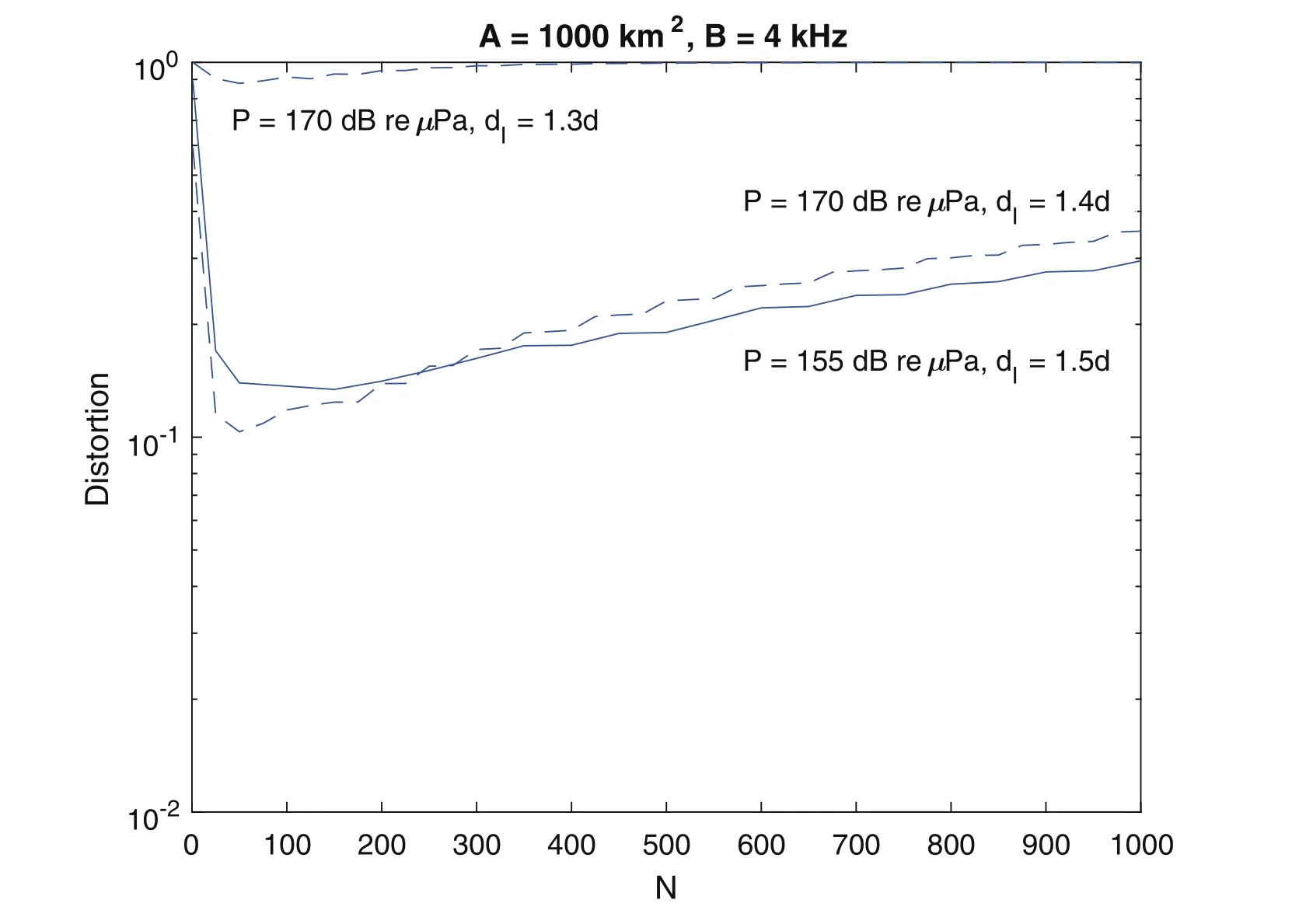
Fig. 7. Comparison of the route distortion with the reserve listen and go protocol with P = 170 dB re μPa and the reserve listen and go protocol with RTS and CTS messages before the transmission phase with P = 155 dB re μPa for R = 4 bits per description.
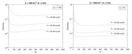
Fig. 8. Distortion for various powers for d I = 1 . 75 d(LHS) and d I = 2d(RHS). R = 4 bits per description.
Fig. 8 illustrates the average route distortion for various transmit powers. The rate isR= 4 bits per description, henceD= 3 . 9 ×10⁻³. In particular, transmit powers ofP= 135 dB re μPa ,P= 145 dB re μPa , andP= 155 dB re μPa are presented. Two scenarios are considered, when the distance to the interferers isdI= 1 . 75danddI= 2d, presented on the left hand side and right hand side of Fig. 8 , respectively. In both cases, the distortion performance improves as the transmit power level is increased.As expected, for the same transmit power level, lower route distortion is achievable in the case whendI= 2d, as compared to the case whendI= 1 . 75d, since the interferers are farther away. It is interesting to note however, that in the scenario whendI= 1 . 75d, it is still possible to achieve comparable route distortion performance to the scenario whendI= 2d, through an increase in the transmit power level of approximately 10 dB re μPa.
Fig. 9 illustrates the average route distortion for different wind speeds. Wind speeds ofw= 0 m/s ,w= 5 m/s ,andw= 10 m/s are considered. The rate isR= 4 bits per description, henceD= 3 . 9 ×10⁻³. The transmission power isP= 155 dB re μPa . It can be observed that the route distortion increases as the wind speed increases, since increased wind speeds result in less favorable propagation conditions.

Fig. 9. Distortion for various wind speeds for d I = 2d. R = 4 bits per description.
5.Conclusions
The paper investigated the distortion performance of mobile underwater acoustic networks for the case of an independent identically distributed (i.i.d.) Gaussian source and single description coding. The direction persistent mobility model was considered. The AUV's utilized a simple demodulate and forward relaying strategy. The average route distortion was investigated in the context of the modified reserve listen and go transmission protocol that included an exchange of RTS/CTS messages before transmission. The modification was introduced in order to alleviate the impact of network interference. This made the network operation possible at significantly lower transmit powers resulting in significant power savings as compared to the reserve listen and go transmission protocol in its original form. It was also observed that the impact on interference strongly depends on distance between the destination and the interferers. Numerical examples illustrated the average route distortion performance for different interferer distances and transmit powers. It was thus observed,that there are scenarios where the impact of increased interference, due to a reduction in the distance between the destination and the interferers, can be compensated by an increase in the transmit power levels. The robustness to diminished propagation conditions due to increased wind speeds was also investigated.
杂志排行

Journal of Ocean Engineering and Science的其它文章
- Development of current-induced scour beneath elevated subsea pipelines
- Optimization approach for a climbing robot with target tracking in WSNs
- The effect of gravity and inclined load in micropolar thermoelastic medium possessing cubic symmetry under G-N theory
- New analytic solutions of the space-time fractional Broer-Kaup and approximate long water wave equations
- Efficient numerical scheme based on the method of lines for the shallow water equations
- Comparing the force due to the Lennard-Jones potential and the Coulomb force in the SPH Method