Study on Multi-Rotary Joints Space Power Satellite Concept
2018-02-20HOUXinbinWANGLi
HOU Xinbin, WANG Li
China Academy of Space Technology, Beijing 100094
Abstract: The Space Power Satellite (SPS) would be a huge spacecraft capturing the power of solar radiation in space and to supply electric power to the electric grid on the ground. The SPS concept was proposed by Dr. Peter Glaser in 1968. SPS have been studied now for exactly fifty years by many scientists in various countries. It has been regarded as one of the most promising energy projects of the future and has been attracting more attention in recent years. More and more Chinese scholars and experts are paying attention to the development of SPS. Due to the huge size, immense mass and high power of such a satellite system, there are many technical difficulties which exist to realize SPS. In this paper, recent SPS research and development activities are reviewed first. Various SPS concepts are analyzed and compared. The primary scheme of the Multi-Rotary joint SPS (MR-SPS) is described. The main feature is that the huge solar array comprising many separate small solar sub-arrays and each solar sub-array has two middle power rotary joints. So, the most challenging technology, the high-power rotary joint, is simplified by using many middlepower rotary joints hence the possibility of a single-point failure of a single rotary joint is avoided. This enables easy assembly of the modular solar arrays. Finally some key technologies of MR-SPS are analyzed.
Key words: Space Power Satellite, space solar power, key technology, MR-SPS
1 INTRODUCTION
The Solar Power Satellite (SPS), was proposed in the journalScienceby Dr. Peter Glaser[1]back in 1968. Hence this year is the 50th Anniversary of Dr. Peter Glaser’s initial proposal.SPS has been regarded as one of the most promising energy projects of the future and is attracting more attention in recent years. There are considerable related research and development plans in the world today[2-3].
China started the study on SPS in 2006. With the support from China National Space Administration (CNSA), Chinese Academy of Science (CAS), National Natural Science Foundation of China (NSFC), more and more Chinese scholars and experts have begun to pay more attention to the development of SPS[4-6].
In 2014, the Xiangshan science conference “The Opportunity and Challenge of SPS Development” was held in Beijing.Over fifty scholars from different fields, including energy, aerospace, power, attended the conference. In 2017, the second Solar Power Satellite Technology Development Seminar was held in Beijing. Ten academicians and over 200 delegates attended the seminar.
In 2014, a special expert team on SPS strategic research was established by CNSA. Over 130 experts from 16 departments and 49 organizations participated in the research.There are also 7 senior consultants including: WANG Xiji, MIN Guirong, LONG Lehao, YANG Shizhong, DUAN Baoyan, GE Changchun and LIU Jizhen. A two-stage roadmap for the SPS were proposed under the initial research and a development plan. The first stage from 2015 to 2035 of the SPS R&D is on systems and key technologies, including a detail system design and simulation, high power WPT, high power space PMAD, deployable space structures and control technology. The second stage from 2036 to 2050 is to develop a GW class commercial SPS based on validated innovative technologies.
An innovative concept is very important for the feasibility of SPS. In 2014, two new concepts were proposed in China.One was an innovative non-concentrator SPS proposed by the China Academy of Space Technology (CAST), named the Multi-Rotary joints SPS (MR-SPS)[7]. The primary scheme of the MRSPS will be described in this paper. Another one was an innovative concentrator SPS proposed by Xidian University, named SSPS-OMEGA[8]. Chinese researchers also studied some other key technologies for SPS, including wireless power transmission,large scale structure and the in-orbit assembly, advanced solar cells and large scale solar array.
2 COMPARISON OF VARIOUS SPS CONCEPTS
More than thirty SPS concepts have been proposed in the world since 1968[9-14]. Typical SPS concepts include the 1979 SPS Reference System, Sun Tower, Sun Disk, Integrated Symmetrical Concentrator (ISC), Abacus and SPS-ALPHA proposed by US, SPS2000, SPS2001, Tethered-SPS and LPT SPS proposed by Japan, Sail Tower proposed by ESA; Aeroboat Relay SPS proposed by Russia plus; MR-SPS and SSPS-OMEGA proposed by China. These SPS concepts can be classified into three types: Type I, sun-pointing non-concentrator SPS; Type II,sun-pointing concentrator SPS; Type III, non-sun-pointing gravity gradient stabilized SPS.
The sun-pointing non-concentrator SPS relies on a power transmission rotate joint to keep the solar array Sun-pointing and the antenna Earth-pointing to generate power continuously and steadily. The very high power rotary joint is the largest technical challenge.
The sun-pointing concentrator SPS utilizes special reflectors to change the direction of sunlight. The design negates the need for high power transmission rotary joints and shortens the transmission electric cables largely to simplify the Power Management and Distribution (PMAD). However the high precise concentrator system and thermal control become two intrac-table technical challenges.
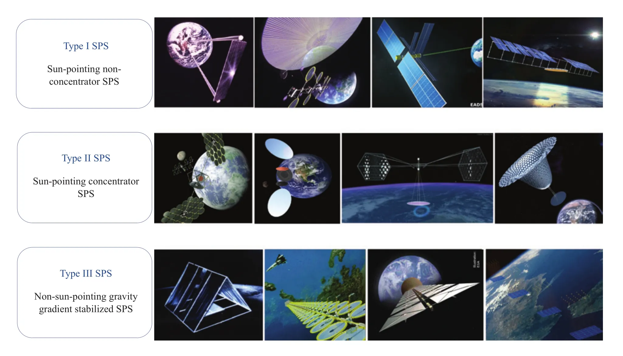
Figure 1 SPS concept types
For a non-sun-pointing gravity gradient stabilized SPS, the position of the solar array is fixed relative to the antenna. The angle between the solar array and the Sun will change from zero to 360 degrees. Therefore, the energy will fluctuate between zero and maximum during the orbit period.
3 MULTI-ROTARY JOINTS SPS CONCEPT
3.1 Introduction
MR-SPS will be a huge spacecraft. Multiple independent solar sub-arrays will point to the sun and convert solar energy to electrical power continuously and steadily (Figure 2). Each subarray will transmit electrical power to the main structure via two independent rotary joints. The main structure and the transmission antenna will be connected and there will be no relative motion between them.
The electrical power generated by sub-arrays will be transmitted to the antenna by cables along the structure trusses.Then the electrical power will be converted to microwave power. The antenna will then transmit high power microwave energy to the rectenna on ground. The rectenna receives the microwave energy and converts it to electric power. The typical receiving power will be 1 GW. The total energy efficiency of the SPS will be about 13%.
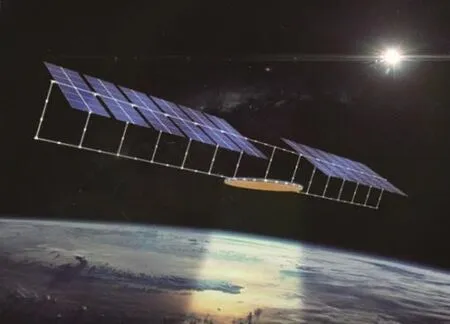
Figure 2 MR-SPS concept
The SPS system includes a Solar Energy Collection and Conversion (SECC) sub-system, Power Transmission and Management (PTM) sub-system, Microwave Power Transmission(MPT) sub-system, Structure sub-system, Attitude and Orbit Control (AOC) sub-system, Thermal Management (TM) subsystem, and Information and System Operation Management(ISRM) sub-system.
3.2 Configuration of MR-SPS
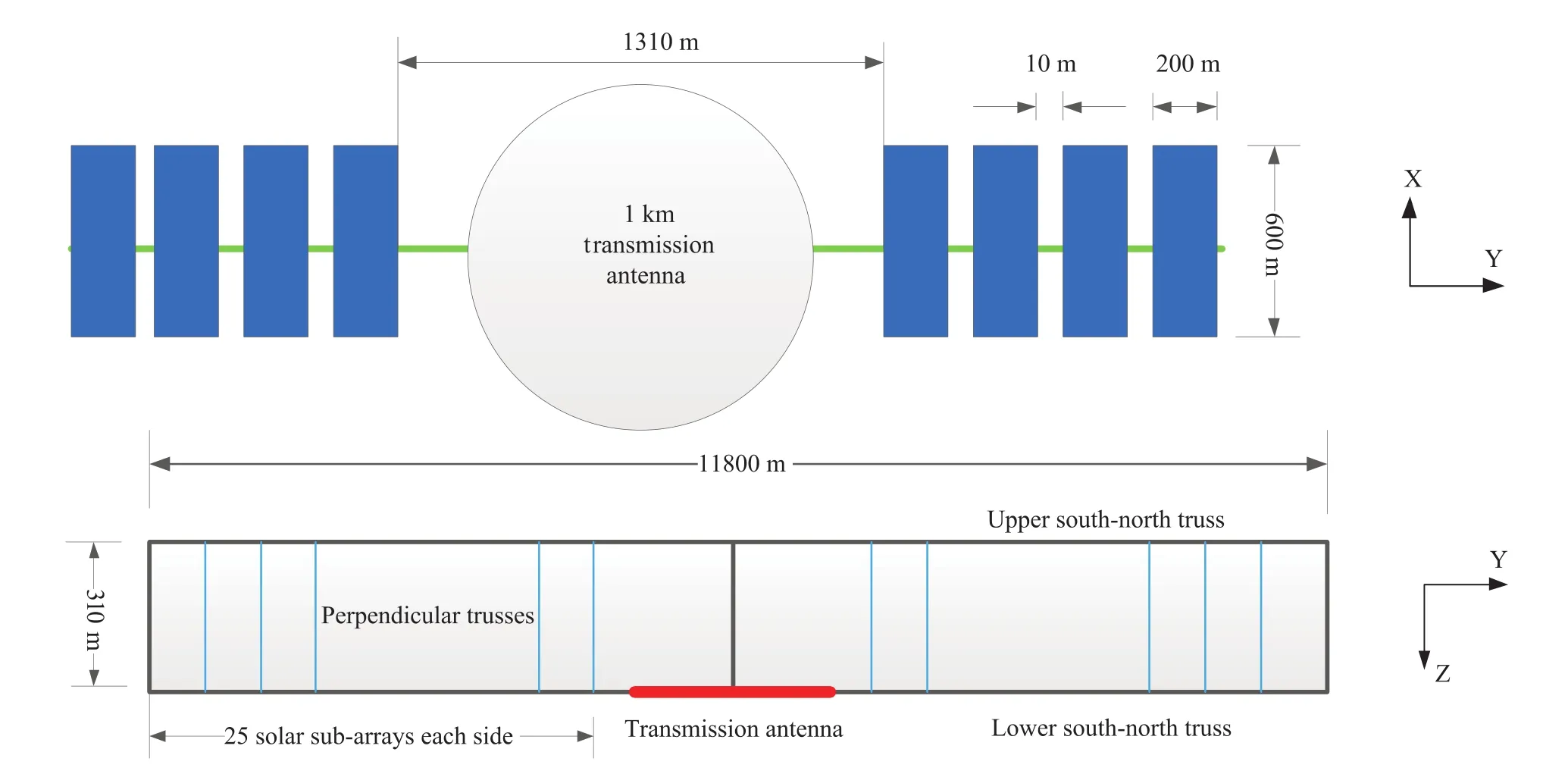
Figure 3 Configuration of MR-SPS
The MR-SPS consists of three key components: solar array,microwave transmission antenna and main structure. The SPS platform devices, including AOC, TM and ISRM sub-systems,will be installed on the solar array, microwave transmission antenna and main structure. Figure 3 shows the conceptional con-figuration and size of a typical 1GW MR-SPS. The solar array consists of 50 solar sub-arrays. The solar sub-arrays will be 10 meters apart. The distance between the two solar sub-arrays on either side of theantenna will be 1,310 meters to avoid an eclipse of the antenna. An antenna with 1,000 m diameter is proposed based on the energy density and transmission distance. Hence, the total length of a SPS will be about 11,800 meters.
The main structure will connect the solar array’sand the microwave transmission antenna. The upper south-north truss supports the solar sub-arrays which will rotate around the truss in orbit to point to the sun. The lower south-north truss supports the microwave transmission antenna. The upper southnorth truss and the lower south-north truss will be connected by many perpendicular trusses.
3.3 Solar Energy Collection and Conversion
According to the efficiency analysis, the SECC will supply 2 GW electric power to MPT system. The whole SECC includes 50 solar sub-arrays. Each solar sub-array is composed of 12 solar array modules which will be divided into two lines and each line will include 6 modules and the whole area will be about 0.12 km2. The power generated by each module will be transferred via the rotary joint first and then will be transferred to antenna by cables installed on main structure of SPS.
Each solar array module wll be composed of a thin-film solar array, trusses and deployment mechanisms. A solar array module will be folded before launch and deploy automatically in orbit. Its size will be about 100 m×100 m and weigh 3 tons.High efficiency GaAs cell have been selected with an efficiency of over 40% is expected. The output power of a solar array module will be about 4 MW. So, the total output power of the SECC will be about 2.4 GW and the weight about 1800 tons.
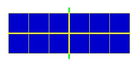
Figure 4 Solar sub-array
3.4 Power Transmission and Management
The primary function of PTM is to combine, convert, transmit and distribute the electrical power of SECC. Amix of distributed and centralized PTM will be adopted. Each solar sub-array will transmit the electric power to the cables via two rotary joints. All cables will be connected to the electric power interfaces of antenna and the electric power will be distributed in the antenna.
For the solar sub-array, main power will be transmitted to the rotary joints. Reduced power will be used for the power supply of service devices and energy storage on the solar subarray. The output voltage of the solar array module will be 500 V. The power will be regulated to 5000 V and transmitted to the rotary joints. For the PTM of the main structure, main power will be transmitted to the electric power interfaces of the antenna. Reduced power will be distributed to service devices(including electric thrusters) and reduced power will be used for energy storage to supply power for service devices during eclipse. The 5000 V output power will be regulated to 20 kV and transmitted to the antenna. For the antenna, mainpower will be transmitted to microwave generators to generate the microwave power signal. Reduced power will be used for the energy supply of service devices and energy storage in antenna.
3.5 Microwave Power Transmission
MPT is the most important sub-system of the SPS. It includes both a space segment and a ground segment. The space segment is composed of a transmitting antenna, microwave generators, microwave phase control circuits, etc. The ground segment is composed of rectennas and a retro-direction beam system. The retro-direction beam control technology will be used to insure high efficiency and high precision (0.0005°) microwave power transmission. The retro-direction beam system will emit a guiding beam to the transmitting antenna in space.The guiding beam signals will be received, analyzed and processed to control the phase of the microwave generators to achieve beam direction adjustment. Rectennas will receive and rectify the microwave power to DC power.
Considering the requirement to have high atmosphere transparency and the size of antenna, 5.8 GHz has been selected for most of the SPS concepts. For a SPS in GEO, A 1 km diameter transmitting antenna and a 5 km diameter rectenna are proposed with an interception efficiency of over 90%.
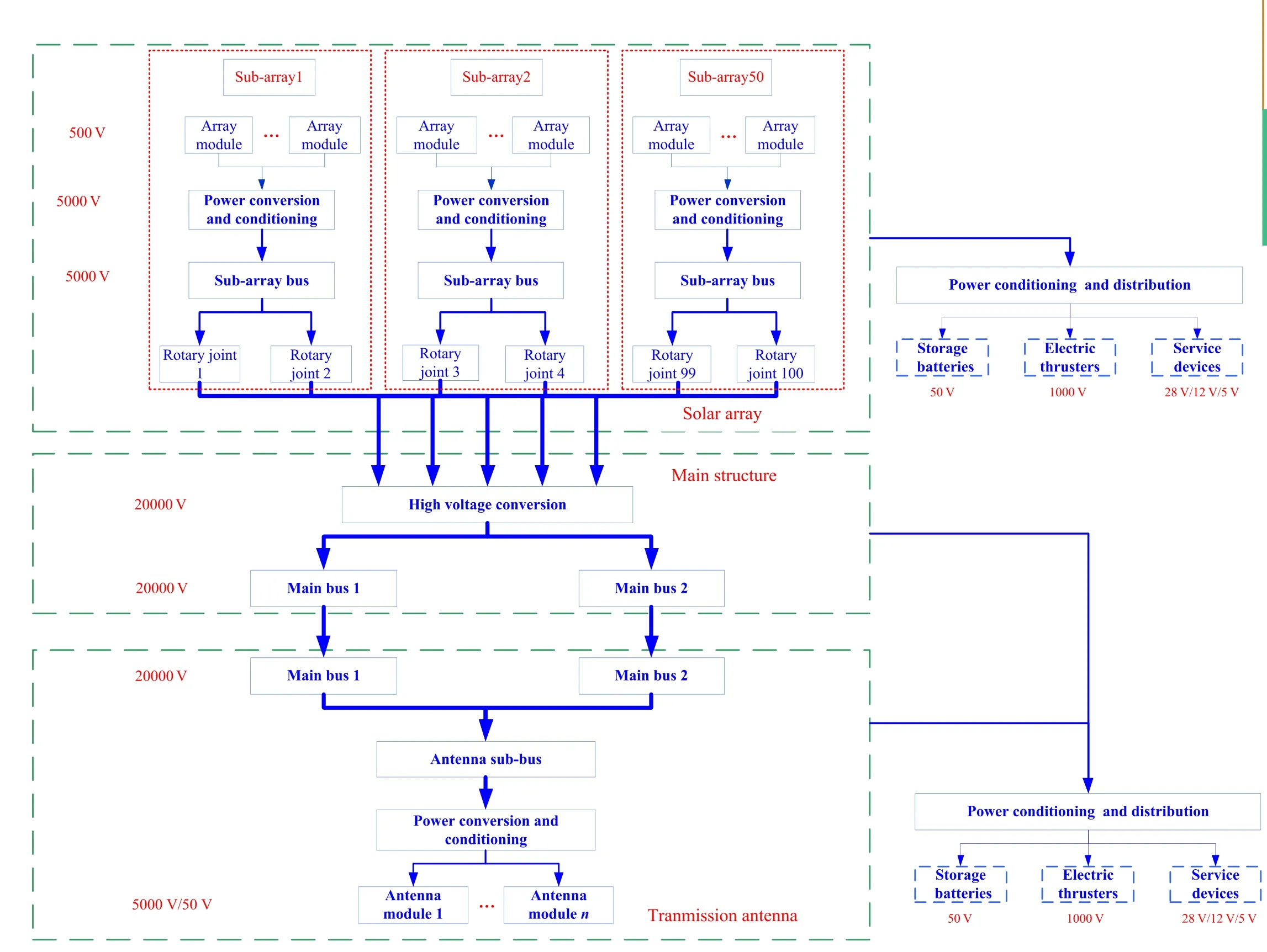
Figure 5 The mix of distributed and centralized PTM

Figure 6 WPT functional architecture
The structure of the antenna will be composed of many truss modules, presented in figure 7. The broken lines represent the idea antenna shape. The thicker solidlines represent the main trusses and the thinner lines represent the sustainment trusses of antenna modules. 80 grids are proposed with each grid 100 m×100 m in size and includes five 20 m×100 m antenna modules. An antenna module will be composed of 320 2.5 m×2.5 m array modules. An array module will be the basic module of the antenna and will include 6400 emit elements.The microwave phase at a special array module will be calibrated by processing the received retro-direction beam signal.
The parameters of a typical 1 GW MR-SPS are summarized in Table 1.
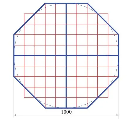
Figure 7 Configuration of the transmitting antenna
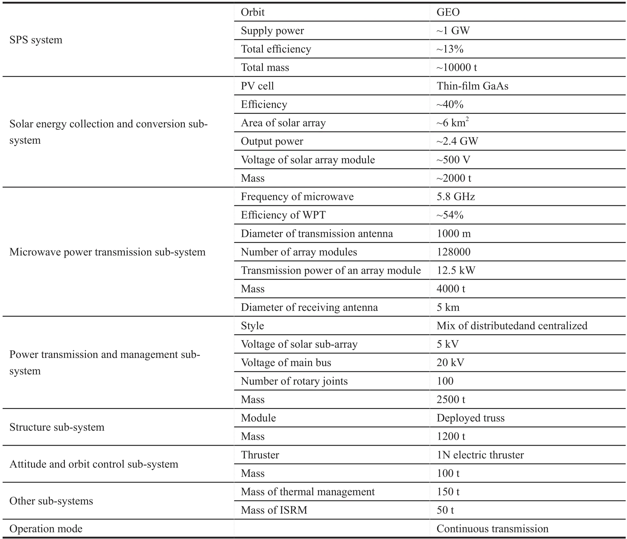
Table 1 Summary of parameters for a 1 GW MR-SPS
3.6 Transportation and Construction
Transportation will be a vitally important aspect which will determine the technical and economic feasibility of a SPS. For the SPS, two space transportation phases are expected. The first phase will be to launch the parts of the SPS from the Earth into LEO using reusable heavy launch vehicles. The second phase will be to transfer the parts from LEO to GEO using reusable electric propulsion systems.
A modular design for the MR-SPS, including truss modules,antenna modules, solar array modules and other modules,will be adopted to make it convenient to enable assembly in space. The scale and complexity of the assembly will considerably exceed that of ISS and it will be impossible to assemble the complete structure by astronauts. A free flying robot and synchronized multi-robots will be necessary technological tools to complete the assembly. A possible assembly sequence is shown in Figure 8. The main structureof the SPS will be assembled first and then the other modules will be assembled on the main structure in sequence.
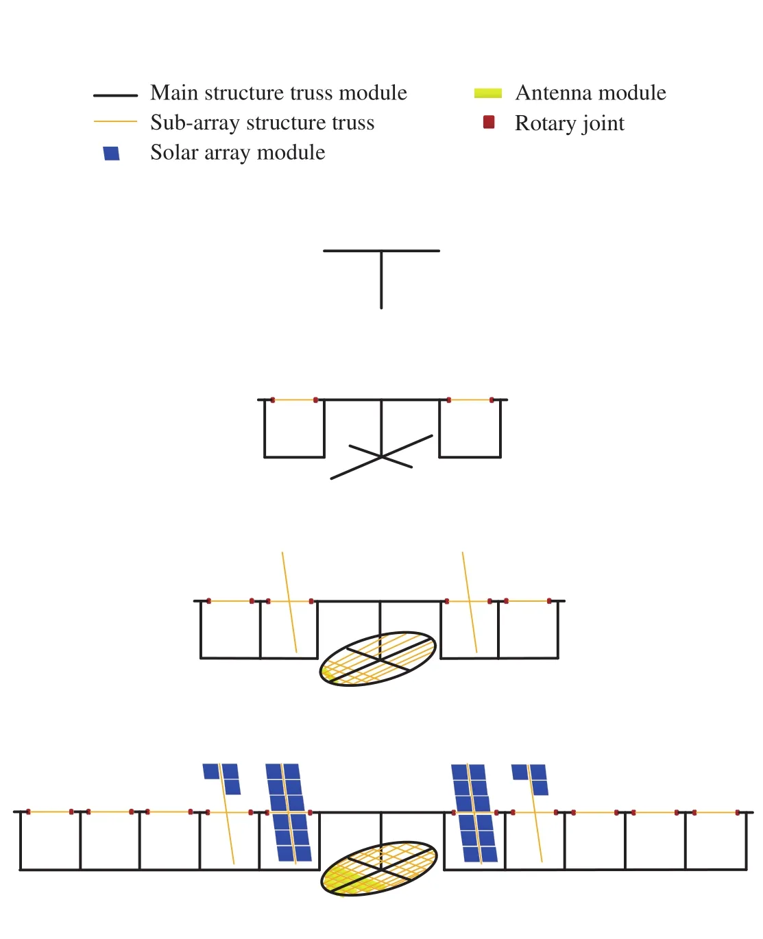
Figure 8 The assembly sequence of a SPS
4 KEY TECHNOLOGIES FOR MR-SPS
SPS will be an amazing macro-engineering project in space.There are still many technological challenges remaining to build a commercial SPS, even to build a demonstration SPS.
1) High power solar power generation SPS will require a ultra large solar array to generate GW electric power. High efficiency, ultra-light, long life solar cells will be very important. Thin film GaAs solar cells are a prospective candidate with an expected efficiency of over 50%. Ultra large, high voltage solar array module technology will also be key. The area will be about 10000 m2and the output voltage will be about 500 V.
2) High voltage electric power transmission For the non-sandwich SPS concept, long distance electric power transmissionwill benecessary. High voltage electric power transmission will be adopted to reduce power dissipation. A voltage over 20 kV is expected. It will be a big problem in space. High efficiency converters and ultra-light cables will benecessary. The high power rotary joint will be another key technology. Although MR-SPS will reduce the power levels from 1.2 GW to 24 MW, it will still be a big challenge.
3) High power wireless power transmission There are several factors to be considered regarding the WPT. Firstly, a km class ultra-light antenna will be a huge challenge and a 4 - 5 kg/m2area-mass ratio is expected. How to construct and how to maintain the precise shape will also be very difficult. Secondly, a high efficiency of over 50% will need high efficiency microwave generators, a high efficiency antenna and a high efficiency rectenna. Thirdly, a beam pointing precision better than 0.0005° will be required and that will mean less than a 314 m distance error. So retro-direction beam control becomes a special important technology.
4) Ultra-large structures and attitude and orbit control For a huge spacecraft of several km2, the structure and control will be very difficult. Each structure module must be big enough to reduce assembly complexity but that means each structure module must be light and deployable in space. New materials and innovative mechanisms will be necessary. For the ultra large flexible structure, a dispersed control method needs to be adopted. High power electric thrusters and large torque momentum wheels will be necessary.
5) Transportation and construction A heavy launch vehicle with low cost will be the largest hurdle to develop SPS. Also a low cost reusable orbital transfer vehicle will be another important technology to reduce cost. A free flying robot and synchronised multirobots technologies will be necessary to assemble the SPS in space.
5 CONCLUSION
SPS has been regarded as one of the most promising energy projects for the future and it has been attracting more attentionin recent years. There are many SPS concepts and each has its own advantages and different technology difficulties. There are still many innovative technologies which need to be studied more deeply.
MR-SPS is a new non-concentrator SPS concept. The most important technological progress will be solving the extremely high power rotary joint problem. The modular design will make the production and assembly easier. However there will be many technological problems before MR-SPS is realized. These key technological problems will need more conceptual studies and new technological innovations will be developed to make the SPS a reality.
杂志排行
Aerospace China的其它文章
- Study on Measuring Device for Bearing Clearance of Hemisphere Dynamic Pressure Motor
- Exploration of CASC’s Commercial Space
- SuperView-1-China’s First Commercial Remote Sensing Satellite Constellation with a High Resolution of 0.5 m
- Space Development with Chinese Characteristics and its Practical Significance
- China Successfully Launches First Operational Civil Optical Constellation
- China Launches BeiDou 3 Navigation Satellites into Space
