Study on Measuring Device for Bearing Clearance of Hemisphere Dynamic Pressure Motor
2018-02-20YANXiaojunYUDetaoTANGZhaofang
YAN Xiaojun, YU Detao, TANG Zhaofang
Beijing Institute of Aerospace Control Devices, Beijing 100039
Abstract: The clearance of the hemisphere dynamic pressure motor is small and difficult to measure, the measurement method of micro clearance is studied. The shortcomings of the original measurement method are analyzed, and a clearance measuring device for the hemisphere dynamic pressure motor is designed, which improves the measurement efficiency and stability.
Key words: hemisphere dynamic pressure motor, measurement of micro clearance, precision measurement, research on device
1 INTRODUCTION
The gyro motor, as the core component of gyro instrument, provides a stable and reliable moment of inertia for gyro instruments. Its performance directly affects the accuracy and reliability of instruments, platforms, even missiles and spacecraft.Implimentation of the supporting methods for gyro motor can be divided into two: ball bearing support and dynamic air pressure bearing support. The dynamic air bearing motor is referred to as a dynamic pressure motor, has the advantages of small volume, low vibration noise, high speed, high reliability, low friction loss, long life and other advantages. It is widely used in all kinds of high precision and high reliability gyroscope instruments, and is also used in aviation, aerospace, marine and in other important instruments[1].
The dynamic air pressure bearing used in a dynamic air bearing motor can be defined as two precision machined surfaces separated by an air film. It takes advantage of the viscosity and stiffness of the air, with the dry compressed air introduced into the air bearing clearance through some blowholes on the surface of the bearing. The clearance of the air bearing is maintained with compressed air, with the air film bearing the pressure load and achieves stable action[2].
With the motor axis as the reference, the air bearing has axial and radial clearance, with its bearing clearance of only 0.003- 0.008 mm, as shown in Figure 1. Therefore, the accurate measurement of the axial and radial clearance of the bearing is the key process in the machining and assembling process of the dynamic pressure motor[3].
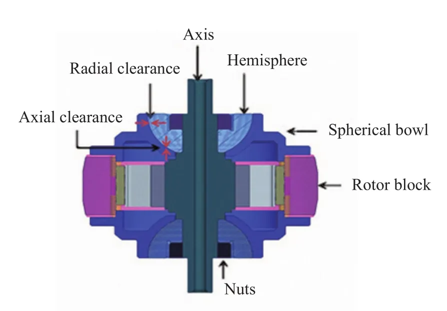
Figure 1 Model of dynamic pressure motor
At present, the measurement of the bearing clearance of the hemisphere dynamic pressure motor depends entirely on the way that the operator manually suspends the weights, as shown in Figure 2. The motor needs to be clamped two times in the axial and radial measurement process, measuring operation efficiency is low, and the reliability is not optimum. It was essential to study a high efficiency measurement method for the motor clearance.

Figure 2 Manual method of clearance measurement
2 RESEARCH ON A HIGH EFFICIENCY MEASUREMENT METHOD FOR BEARING CLEARANCE FOR THE HEMISPHERE DYNAMIC PRESSURE MOTOR
The bearing clearance of the hemisphere dynamic pressure motor is very small. A set of devices which can accurately and efficiently measure the axial and radial clearance was urgently needed to solve the complicated and inefficient measurement methods.
2.1 Selection of Measuring Sensors
A displacement sensor is the key component for the motor clearance measurement device. Its precision and other performance indexes have the greatest impact on the accuracy of the whole system. Therefore, it is a prerequisite and key to ensure the precision of the system to select a high-precision displacement sensor which is suitable for the performance and to meet the requirements of the measurement[4]. The measurement of bearing clearance for the dynamic motor requires that the resolution of displacement sensor is 0.1 μm. The motor rotor is not rotated when measuring, so a contact or non-contact sensor can be used. In order to meet the requirements for the clearance measurement, the displacement sensor should have the characteristics of high precision, high sensitivity and have a high frequency response.
The two kinds of sensors in accordance with the above requirements are the inductance micrometer (contact type) and capacitance micrometer (non-contact type). The capacitance micrometer is subject to the edge effect, electromagnetic interference and other environmental factors. Hence there are several problems in the application of capacitance sensors for the measurement of motor clearance. First of all, the capacitance sensor is more sensitive. If the installation position is not accurate or subjected to external vibration and other disturbances,it will be prone to larger errors. Another problem is that when measuring the radial clearance of a smaller motor, the measured surface is small or the curvature is large, which will lead to the enhancement of the edge effect of the capacitance sensor and seriously affect the measurement result and make the measurement result inaccurate[5]. In view of the above analysis, the inductor micrometer is the preferred solution.
2.2 Introduction of the Measuring Principle of the Clearance Measuring Device
The device uses contact measurement and contact loading to measure the clearance of the motor, as shown in Figure 3.An inductor micrometer is arranged at both ends of the motor shaft in radial and axial directions, and a contact loading device is arranged on the opposite side of each inductor micrometer.Each of the inductance micrometers and the loading device is equipped with a trimming device for adjusting the distance between the part and the motor shaft.
Take the axial clearance measurement as an example, as shown in Figure 3. First, the axial loading devices are placed under the motor; the loading device is not working at this time.The inductor micrometer on the opposite side is adjusted to contact the motor shaft, and the position value A1 in the selfweight state is measured. Next, the loading device is operated,and as the spring compresses, the load force reaches its pre-determined value, and the inductance micrometer measures the position value A2in the loaded state. The data acquisition card collects the test data and calculates the axial clearance for ΔA=A2-A1. The radial clearance measurement approach is the same as the axial measurement principle, and the detailed measurement process is shown in Figure 4.
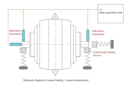
Figure 3 Schematic diagram of clearance measuring device
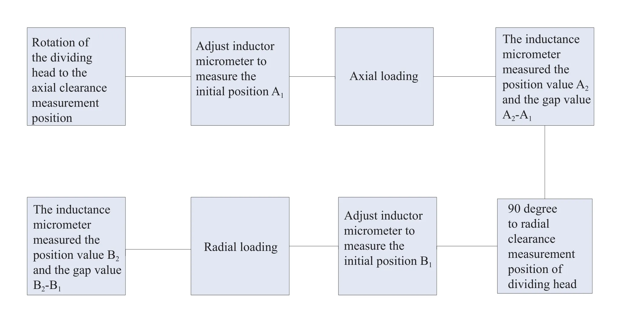
Figure 4 Clearance measurement working process
3 COMPONENT AND FUNCTION MODULE OF MOTOR CLEARANCE MEASUREMENT DEVICE
The dynamic pressure motor clearance measuring device consists of three main modules, including the attitude control module, the contact loading module and the contact measurement module. By means of attitude switching, the motor can be installed at one time, and the clearance value in the two directions can be measured efficiently and accurately.
3.1 Attitude Control Module
The device adopts as witching attitude to measure the clearance, and the motor is installed once for the measurement.The sensor and the dynamic pressure motor are all fixed on a bracket, and can rotate around 360 degrees under the action of a dividing head. The axis of the sensor is perpendicular to the motor axis, and the relative position is fixed. By rotating the motor by 90 degrees, efficient switching between axial and radial direction can be realized, as shown in Figure 5 and Figure 6.
3.2 Contact-type Loading Module
Three of the contact loading modules are arranged in the radial and axial directions, and the structure diagram is shown in Figure 7. By turning the adjusting nut (7), the slider (4) moves forward until the push rod (8) contacts the motor shaft. By continuing to rotate the adjusting nut (7) compression of the spring occurs. Once the pressure sensor (5) shows that the pressure value is up to its preset value, the adjusting nut (7) rotation is stopped, and the quantitative loading of the motor is completed.
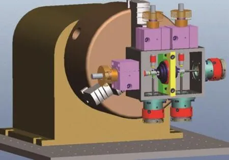
Figure 5 Radial clearance measurement
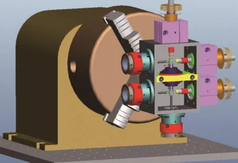
Figure 6 Axial clearance measurement

Figure 7 Schematic diagram of contact-type loading module
3.3 Contact-type Measurement Module
According to the analysis of the measuring sensors above,the device uses inductance micrometers to measure the clearance of the motor. Each inductance micrometer is equipped with a fine-tuning device to adjust the working distance between the head and the motor. The measurement module is arranged on the opposite side of the loading module, the structure is shown as shown in Figure 8. The probe (1) is fixed to the adjustment slider (4) by a cone (2); rotation of the adjusting nut (5)realizes the position adjustment of the probe (1). After adjusting to the appropriate measurement position, the screw (3) is tightened to fix the head and the measurement can be started.
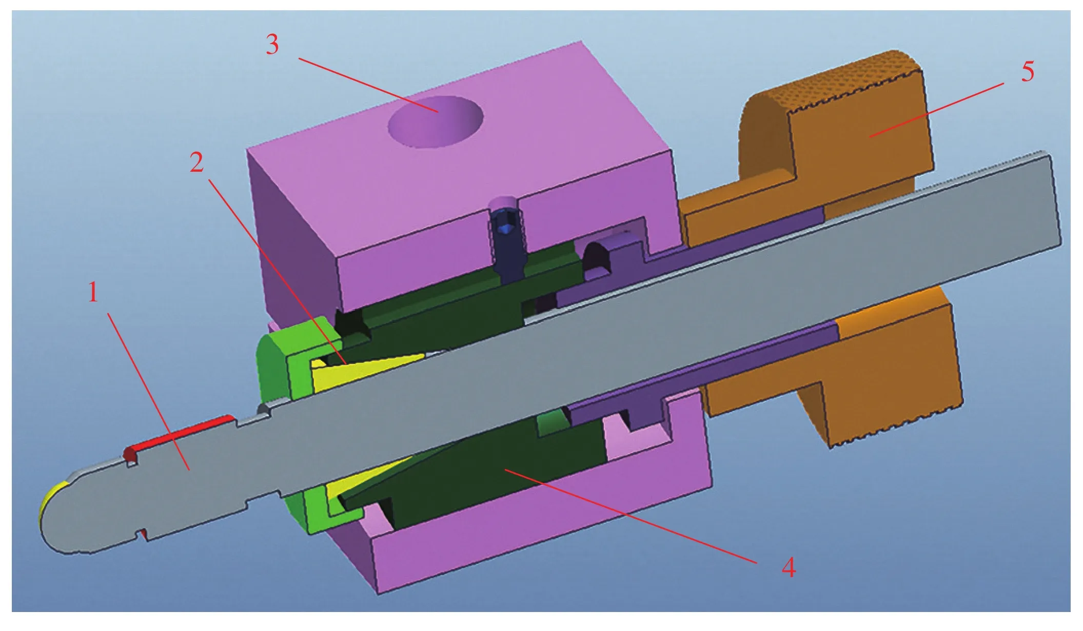
Figure 8 Schematic diagram of sensor turning device
4 ANALYSIS OF EXPERIMENTAL RESULTS OF THE MOTOR CLEARANCE MEASUREMENT DEVICE
The motor clearance measuring device uses dual way dividing head to switch the measuring attitude, avoiding the need to repeat the loading measurement process, and the loading method is simple, which greatly improves the efficiency. For the experiment, the measurement time for the motor clearance measurement device is less than 2 min, while the traditional manual measurement time is about 10 min, so the efficiency has increased by more than 5 times.
The loading and measuring methods of the clearance measuring device are stable and reliable, so the measurement data is more stable than the manual measurement. Taking the radial clearance as an example, as shown in Table 1, the motor rotates 60 degrees to measure one point, and the average value of 6 measurements is taken. The same measurement method takes 6 times. The maximum deviation is 0.025 μm, and the average value of radial clearance is 3.033 μm. The accuracy and reliability of measurement are higher than manual measurement.

Table 1 Measurement results of radial clearance of bearing
5 CONCLUSIONS
1) Through the research the efficient measurement method of the bearing clearance of the hemisphere dynamic pressure motor, the working conditions of the two displacement sensors are compared, and the contact inductance micrometer was selected as the sensor for measuring the clearance of the motor. By means of attitude switching, the motor can be installed once, and it simplifies the measurement process.
2) The function modularization of the motor clearance measurement device is realized through the design of an attitude control module, a contact loading module and a contact measurement module. The precision and efficiency of the motor clearance measurement are improved by the design of the fine-tuning device.
杂志排行
Aerospace China的其它文章
- Study on Multi-Rotary Joints Space Power Satellite Concept
- Exploration of CASC’s Commercial Space
- SuperView-1-China’s First Commercial Remote Sensing Satellite Constellation with a High Resolution of 0.5 m
- Space Development with Chinese Characteristics and its Practical Significance
- China Successfully Launches First Operational Civil Optical Constellation
- China Launches BeiDou 3 Navigation Satellites into Space
