A Time-Saving Method to Prepare Monodisperse Fe3O4 Microspheres with Controllable Sizes and Morphologies
2018-01-12WANGDanLIUChuanYongLONGYueSONGKaiHUANGWei
WANG Dan LIU Chuan-Yong LONG Yue SONG Kai HUANG Wei
A Time-Saving Method to Prepare Monodisperse Fe3O4Microspheres with Controllable Sizes and Morphologies
WANG Dan1,3LIU Chuan-Yong2LONG Yue3SONG Kai3,*HUANG Wei1
(1;2;3)
Monodisperse Fe3O4microspheres with tunable diameters and high magnetic saturation were synthesized by a solvothermal reduction method. It was found that the morphology and structure of the Fe3O4microspheres could be tuned by simply altering the amount of the reactants such as ferric chloride, sodium acetate, water, and the reaction time. The Fe3O4microspheres obtainedthis method possessed high purity, crystallinity, and a nearly spherical shape. Furthermore, they were monodispersed and no aggregation was found. Such monodisperse Fe3O4microspheres had tunable diameters of 400–700 nm and the fabrication time was only 2–4 h. The products showed high magnetic saturation values, and their yields were typically more than 94%.
Monodisperse Fe3O4microspheres; Solvothermal; Time-saving; Tunable
1 Introduction
In the past few years, magnetic microspheres have gained much attention owing to their wide application areas, such as magnetic separation1−4, targeted drug delivery5, catalyst6, magnetic resonance imaging (MRI)7,8, magnetic ink9, magneto-optical applications10and self-assembly11. As the magnetic, transportation properties, catalysis, biomedicalare directly controlled by particlesize, size distribution, shape and surface chemistry12,13, the synthesisof nanostructured magnetic materials has become aparticularly important area of research14–16. Monodisperse Fe3O4microspheres with narrow size distribution, hollow space and high magnetic saturation (σ) can provide maximum signal in liquid media and show high performance in biological, separation and optical applications10,17,18.
Numerous approaches have been developed to synthesize nanostructured monodisperse Fe3O4microspheres including hydrothermal reactions19, co-precipitation20, microemulsion21, solvothermal reduction22, thermal decomposition23, and high-temperature hydrolysis reaction24–27. Among these methods, solvothermal reduction is one of the most frequently-used means to prepare magnetic microspheres with narrow size distribution and high magnetic saturation for it is simple and inexpensive. Li.22used the solvothermal reduction method to prepare monodisperse Fe3O4microspheres with diameters ranging from 200 to 800 nm, and the size of Fe3O4microspheres was tuned by adjusting the reaction time from 8 h to 72 h. Fu.29prepared well-crystallized Fe3O4hollow microspheres with diameters of 200–300 nm, and the reaction was completed in 12 h. Zhao.21modified solvothermal method and tuned the size of Fe3O4microspheres by varying the concentration of the reactants, obtaining the microspheres with average diameters ranging from 80 to 410 nm after 10 h reaction. Zhu.30reported a facile solvothermal method to fabricate hollow Fe3O4microspheres with the diameter of 290 nm for 10 h at 200 °C. Xia31.reported a bisolvent solvothermal processto prepare monodisperse Fe3O4microsphereswith diameters of 55–500 nm for 20 h, and the size was controlled by adjusting the volume ratio of the solvent. From the above methods, magnetic Fe3O4microspheres with different sizes and morphologies were successfully prepared. However, one drawback of the solvothermal method is that the reaction time is relatively long to prepare microspheres with large sizes, e.g. 10 h reaction is required to prepare microspheres with diameter of 400 nm; microspheres with diameters of 600 and 800 nm requires 48 and 72 h to prepare, respectively.
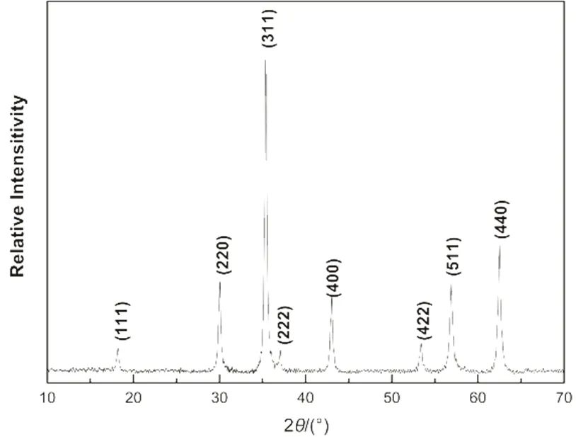
Fig.1 XRD diffraction patterns of the Fe3O4 microspheres.
Herein, the solvothermal reduction method is modified to synthesize monodisperse Fe3O4microspheres with tunable diameters, high magnetic saturation in a short reaction time. The monodisperse Fe3O4microspheres with average diameters ranging from 400 to 700 nm were successfully obtaineda 4 h reaction, and the diameter can be tuned by the amount of ferric chloride, sodium acetate and the reaction time. Moreover, Hollow structure can also be obtained by simply altering the amount of water in the reaction system.
2 Materials and methods
2.1 Materials
Ferric chloride (FeCl3, anhydrous, > 98%) and sodium acetate (CH3COONa, NaAc, anhydrous, > 99%) were purchased from Acros. Ferric chloride hexahydrate (FeCl3·6H2O, > 98%), ethylene glycol (EG, > 99%) and ethanol were obtained from Beijing Chemical Works and used without further purification.Polyethylene glycol (PEG,w ~2000) was purchased from Alfa Aesar. Water used throughout all experiments was purified with the Millipore system.
X-ray diffraction (XRD) analysis was carried out on a D/Max 2500V/PC (Japan) X-ray diffractometer (= 0.154056 nm) in the 2range of 10°–70° using Cu-Kradiation. Scanning electron microscope (SEM) images were obtained by JEOL S-4800 (Japan) field emission scanning electron microscope. Transmission electron microscope (TEM) images and high resolution (HR) TEM images were taken on JEOL JEM-2100F (Japan) transmission electron microscope. The magnetic properties of the Fe3O4microspheres were investigated by SQUID vibration sample magnetometer (VSM) (America).
2.2 Synthesis of monodisperse Fe3O4 microspheres.
In a typical synthesis of Fe3O4microspheres, NaAc (2.87 g) was dissolved in EG (20 mL), and the solution was kept in a water bath at 40 °C. FeCl3·6H2O (2.70 g, 10 mmol) was dissolved in EG (10 mL) to form a clear solution, followed by the addition of PEG (0.75 g). After complete dissolution, the resulting solution was slowly poured into the as-prepared NaAc solution under vigorous stirring at 40 °C. After 30 min, brownish yellow solution was produced, and transferred into a 40 mL Teflon lined stainless-steel autoclave. The autoclave was maintained at 200 °C in oven for 4 h. After cooled down to room temperature, the dark product was collected by a magnet and washed with ethanol and water several times. Finally, the product was dried in room temperature and weighed.
2.3 Characterization of the Fe3O4 microspheres
XRD pattern of the Fe3O4microspheres synthesized by the method in section 2.2 is shown in Fig.1. The diffraction peaks match well with the database for magnetite in the JCPDS-International Center for Diffraction Data (JCPDS Card: 79-0419) file. The specific sharp and strong diffraction peaks also confirmed the well crystallization of the product, and no impurity was observed.
SEM and TEM images were taken to investigate the morphology and structure of theproduct, as shown in Fig.2. It can be seen from Fig.2a that the Fe3O4microspheres are spherical with a uniform size distribution and the average diameter of the spheres is ~600 nm. Rough surface morphology of the microspheres is observed from the magnified SEM image shown in Fig.2b. More details can be found by the broken spheres (observed occasionally) shown in Fig.2c that Fe3O4microspheres are comprised by many aggregated Fe3O4nanocrystals. The TEM images shown in Fig.2d and 2e further confirmed the spherical structure of Fe3O4microspheres. The detailed structure information of the Fe3O4microspheres was investigated by using HRTEM (taken from the marked area in Fig.2e). Clear lattice fringes can be observed in the HRTEM image (Fig.2f), and it also displays the high crystalline and single-crystalline nature of Fe3O4microspheres. The spacing of the lattice fringes is ~0.48 nm, which matches well with the (111) lattice planes of Fe3O4crystal.
The magnetic properties of the Fe3O4microspheres were investigated with VSM. Fig.3 shows the hysteresis loop measured at room temperature by cycling the field between −10 and 10 kOe. Results show that the magnetic saturation value of the microspheres at room temperature is 80 emu·g-1, and the inset curve reveals the weak ferromagnetism behavior of the product with a remanence of 2.9 emu·g-1and a coercivity of 23.7 Oe.
3 Results and discussion
3.1 Modifed solvthermal method
There are two dynamical stagesin the Fe3O4microspheres formation process32. The first stage is the burst-nucleation, forming nanocrystals in the supersaturated solution. The second stage is the oriented aggregation of nanocrystals formed in the first stage to minimize the surface energy. By adjusting these two processes, the morphology and structure of the product can be tuned. In previous studies, attentions were focused on adjusting the ratio of the reactants and solvents in the synthesis system.
However, we found that the precursor solution also has a severe impact on the final product. The conventional way to prepare the precursor solution is to dissolve the FeCl3·6H2O, NaAc solid and surfactant (PEG) consecutively in the EG solution under vigorous stirring. Here, we report a new time-saving method to prepare Fe3O4microspheres: FeCl3·6H2O was dissolved in EG firstly, and then adding PEG to form solution A. NaAc was dissolved separately in EG to form solution B, followed by the combination of solutions A and B. For comparison, precursor solutions using both the conventional method and the new method were prepared, and heated at 200 °C for4 h to produce the Fe3O4microspheres. From the SEM image in Fig.4a, it can be seen that the Fe3O4microspheres prepared by the conventional method are heterodisperesed in size with diameters ranging from a few nanometers to few hundred nanometers. In contrast, the microspheres fabricated by the time-saving method are much more monodisperse with the average diameter of ~600 nm, as seen in Fig.4b. It is widely accepted that a homogenous system is the key for the preparation of monodisperse particles33, so it is important to make a homogenous precursor solution.
The time-saving mechanism remains unclear, while a possible one could be due to the liquid-liquid mixing strategy in our method. In the conventional method, when NaAc was added to the EG solution of FeCl3·6H2O, it started to dissolve. As NaAc is in the solid form, the dissolved NaAc will react with the FeCl3·6H2O firstly, which results in the inhomogeneous of the whole system with dissolution and reaction occurs at the same time. Therefore, the Fe3O4microspheres synthesized from this method is also inhomogeneous in size. Comparatively, in the time-saving method, FeCl3·6H2O and NaAc are dissolved separately in EG first, after combination, reaction carries out simultaneously; hence, is more likely to form a homogeneous system and consequently monodispersed microspheres. In addition, liquid-liquid mixing has larger reaction interfaces than the liquid-solid one. The interface of the following reaction enlarges correspondingly due to the increased total surface of the precursor. In turn, the whole reaction time could be reduced. Hence, in accordance with our explanation, after 4 h of reaction at 200 °C, the yield of the products prepared by the conventional process was ~85%, and the yield of the time-saving process was ~94%.
The synthesis conditions: 2.70 g FeCl3·6H2O, 0.75 g PEG, 2.87 g NaAc, 30 mL EG, 200 °C, and 4 h.

Fig.3 Hysteresis loop of Fe3O4 microspheres.
3.2 Size modification of monodispersed Fe3O4 microspheres
3.2.1 Adjusting the amount of FeCl3·6H2O
Amount of FeCl3·6H2O in the precursor solution affects the size distribution of the Fe3O4microspheres. It was found that no Fe3O4microspheres were obtained with 1 mmol of FeCl3·6H2O added in the precursor solution. When increasing the amount of FeCl3·6H2O to 2 mmol, aggregated Fe3O4microspheres were formed, which can be seen in Fig.5a. When the amount of FeCl3·6H2O increased to 3 mmol, uniform Fe3O4microspheres were produced with the average diameter of 500 nm, as depicted in Fig.5b. As further increasing the FeCl3·6H2Ocontent to 5 and 10 mmol, Fe3O4microspheres with average diameters of 570 nm (Fig.5c) and 600 nm (Fig.5d) were produced, respectively.
The effect of amount of FeCl3·6H2O on the formation of Fe3O4microspheres can be explained withthe help of the two-stage growth model described in section 3.1. When the amount of FeCl3·6H2O was too low, the nucleation process was impeded, which resulted in low yield. With more FeCl3·6H2O added to the precursor solution, the nucleation and formation process of nanocrystals started off. At lower rate, slow formation of the nanocrystals caused the widening of the size distribution, as shown in Fig.5a. When the amount of FeCl3·6H2O increased, the nucleation of the nanocrystals became faster, which accelerated the rate of the nanocrystals formation, and resulted in narrower sizedistribution.
3.2.2 Adjusting the amount of NaAc
To investigate the effect of NaAc, a series of experiments were carried out with different amount of NaAc, whereas other parameters remained constant. When the molar ratio of NaAc/ Fe3+is 1 : 1, the product was polydispersed in size, as shown in Fig.6a. After adjusting the ratio to 2 and 3, uniform microspheres were produced with the average diameters of 400 nm (Fig.6b) and 700 nm (Fig.6c), respectively. However, as the ratio increased to 3.5, the average diameter of the Fe3O4microspheres decreased to 600 nm (Fig.6d). Further reduction of the average diameters was also observed when the NaAc/Fe3+molar ratio increased to 6 (550 nm, Fig.6e) and 9 : 1 (400 nm, Fig.6f). It was also found that the yields of the first two batches (Fig.6a and 6b) are 15% and 55%, respectively, while all the others are over 94%. It can be deduced from the results that low yields of the first two batches are caused by the shortage of NaAc.

Fig.4 SEM image of Fe3O4 microspheres prepared through different processes.
(a) conventional method; (b) time-saving method. All scale bars are 5 μm.

Fig.5 SEM images of Fe3O4 microspheres prepared with different amount of FeCl3·6H2O.
(a) 2 mmol, (b) 3 mmol, (c) 5 mmol, (d) 10 mmol. All scale bars are 2 μm.
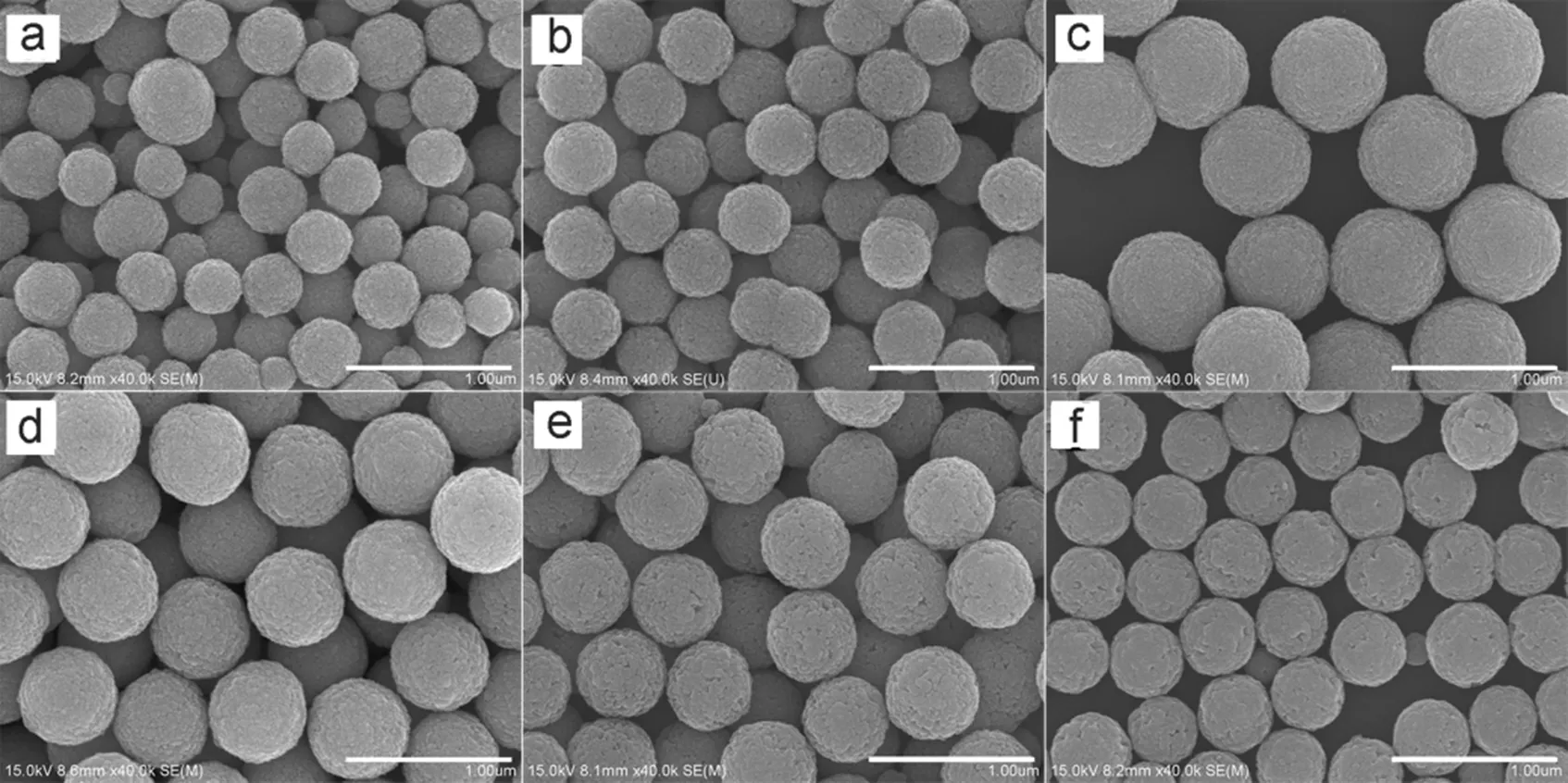
Fig.6 SEM images of Fe3O4 microspheres prepared with different amount of NaAc.
The molar ratio of NaAc/Fe3+: (a) 1, (b) 2, (c) 3, (d) 3.5, (e) 6, (f) 9. All scale bars are 1 μm.
The effect of NaAc on the size of the Fe3O4microspheres can be explained that when the amount of NaAc was low, it caused the slow nucleation of the nanocrystals; hence, resulted in the wider size distribution. As the amount of NaAc increased, the nucleation rate of the nanocrystals became faster, which accelerated the formationof the Fe3O4nanocrystals and resulted in the narrow size distribution31. High amount of NaAc can act as a electrostatic stabilizer which prevents the newly formed microspheres from aggregation. This is also helpful to narrow the size distribution. With the same amount of ferric chloride, faster nucleation leads to the decrease in particle size, which can explain the decrease of size when the molar ratio further increased to 6 and 9. Moreover, electrostatic stabilization also facilitates the oriented attachment. With the increase amount of NaAc, the diffraction peaks became sharper and stronger as one can be seen from the XRD patterns (Fig.7). The corresponding grain sizes increased from 20 to 64.8 nm, which were calculated by the Scherrer equation based on the strongest peak (311) in Fig.734.
3.2.3 Adjusting the heating time
Heating time also affects the size of Fe3O4microspheres. Results show that no Fe3O4microspheres were formed if the heating time is less than 2 h. As the heating time increased to 2 h, Fe3O4microspheres with average diameter of 400 nm were formed (Fig.8a). When the heating time further increased to 3 and 4 h, the diameters of the Fe3O4microspheres increased to 500 nm (Fig.8b) and 600 nm (Fig.8c), respectively. However, no increase in size was found with further prolonged heating (6 h, Fig.8d). This result shows that the diameter of the Fe3O4microspheres can be tuned from 400 to 600 nm by increasing the heating time from 2 h to 4 h, which is much shorter than the reaction time reported in the previous study22.
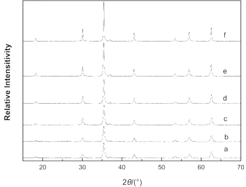
Fig.7 XRD diffraction patterns of the Fe3O4 microspheres prepared with different amount of NaAc.
The molar ratio of NaAc/Fe3+and the grain sizes of peak (311): (a) 1, 20 nm; (b) 2, 22.7 nm; (c) 3, 23.2 nm; (d) 3.5, 28.3 nm; (e) 6, 31.4 nm; (f) 9, 64.8 nm.

Fig.9 SEM images of Fe3O4 microspheres prepared with different amount of water.
The molar ratio of H2O/Fe3+: (a) 6, (b) 9, (c) 12, (d) 18.All scale bars are 2 μm.
3.3 Tuning the morphology of the monodisperse Fe3O4 microspheres
The amount of water can affect the morphology of the Fe3O4microspheres, and anhydrous FeCl3was used instead of FeCl3·6H2O in the preparation process. When the molar ratio of H2O/Fe3+was 6, the product showed uniform size distribution with the average diameter of 600 nm, as shown in Fig.9a. When the molar ratio increased to 9, slight decrease in the average diameter was observed, and small holes appeared on the surface of the microspheres (Fig.9b). After further increasing the molar ratio to 12, the average diameter decreased to 500 nm, as depicted in Fig.9c. It can be seen from the inset image that some of the microspheres became hollow structured. As the molar ratio increased to 18, the average diameter remained as 500 nm. However, a greater portion of the microspheres became hollow, some were even ruptured (Fig.9d).As mentioned earlier, faster nucleation leads to the decrease in particle size. High amount of water gives rise to fast hydrolysis of FeCl3and NaAc, which accelerates the nucleation of the Fe3O4nanocrystals26. Hence, it is comprehensible that the size of the microspheres decreased with the increase amount of water. In addition, the viscosity of the solution decreases with high amount of water, which facilitates the growth and aggregation of the nanocrystals. So the aggregation process at the beginning was very fast, and there is not enough time for the aggregated nanocrystals to adjust and rotate to the suitable configuration interface. Naturally the interior aggregated nanocrystals of Fe3O4microspheres were not oriented as well as the outer ones and had relatively higher surface energy and smaller size. Therefore, they were unstable and gradually dissolved and attached to the outer nanocrystals by the driving force to reduce the overall surface energy. This “solid-solution-solid” mass transportation resulted in the hollow structure of the products35,36.

Fig.8 SEM images of Fe3O4 microspheres prepared with different reaction time.
(a) 2 h, (b) 3 h, (c) 4 h, (d) 6 h.All bars are 1 μm.
4 Conclusions
In conclusion, monodisperse Fe3O4microspheres with average diameters ranging from 400 to 700 nm were successfully synthesized by a time-saving solvothermal reaction route for 2−4 h, and the size of Fe3O4microspheres can be tuned by variousmeans: amount of ferric chloride and sodium acetate, and reaction time. Moreover, hollow structure can also be obtained by simply altering the amount of water in the reaction system. The products have high magnetic saturation values, and the yield of the products is over 94%.
(1) Ge, J. P.; Zhang, Q.; Zhang, T. R.; Yin, Y. D.2008,, 8924. doi: 10.1002/anie.200803968.
(2)Sheng, W.; Wei, W.; Li, J. J.; Qi, X. L.; Zuo, G. C.; Chen, Q.; Pan, X. H.; Dong, W.2016,, 1116. doi: 10.1016/j.apsusc.2016.07.061.
(3) Yu, M.; Di, Y.; Zhang, Y.; Zhang, Y. T.; Guo, J.; Lu, H. J.; Wang, C. C.2016,, 74. doi: 10.3390/polym8030074.
(4) Zhou, L. M.; Wang, Y. P.; Huang, Q. W.; Liu, Z. R.2007,(12), 1979. [周利民, 王一平, 黄群武, 刘峙嵘. 物理化学学报, 2007,(12), 1979.]doi: 10.3866/PKU.WHXB20071228.
(5) Jain, T. K.; Morales, M. A.; Sahoo, S. K.; Leslie-Pelecky, D. L.; Labhasetwar, V.2005,, 194. doi: 10.1021/mp0500014.
(6) Ge, J. P.; Huynh, T.; Hu, Y. X.; Yin, Y. D.2008,, 931. doi: 10.1021/nl080020f.
(7) Qiao, R. R.; Yang, C. H.; Gao, M. Y.2009,, 6274. doi: 10.1039/b902394a.
(8) Kim, D. H.; Chen, J.; Omary, R. A.; Larson, A. C.2015,, 477. doi: 10.7150/thno.10823.
(9) Ge, J. P.; Goebl, J.; He, L.; Lu, Z. D.; Yin, Y. D.2009,, 4259. doi: 10.1002/adma.200901562.
(10) Kim, H.; Ge, J. P.; Kim, J.; Choi, S.; Lee, H.; Lee, H.; Park, W.; Yin, Y. D.; Kwon, S.2009,, 534. doi: 10.1038/NPHOTON.2009.141.
(11) Ge, J. P.; Hu, Y. X.; Zhang, T. R.; Yin, Y. D.2007,, 8974. doi: 10.1021/ja0736461.
(12) Sun, S. H.; Murray, C. B.; Weller, D.; Folks, L.; Moser, A.2000,, 1989. doi: 10.1126/science.287.5460.1989.
(13) Hyeon, T.; Lee, S. S.; Park, J.; Chung, Y.; Na, H. B.2001,, 12798. doi: 10.1021/ja016812s.
(14) Yan, L.; Wang, Y. F.; Li, J.; Shen, H. D.; Wang, C.; Yang, S. B.2016,, 10616. doi: 10.1007/s10854-016-5156-3.
(15) Bokharaei, M.; Schneider, T.; Dutz, S.; Stone, R. C.; Mefford, O. T.; Hafeli, U. O.2016,, 1. doi: 10.1007/s10404-015-1693-y.
(16) Wang, X. M.; Huang, P. F.; Ma, X. M.; Wang, H.; Lu, X. Q.; Du, X. Z.2017,, 300. doi: 10.1016/j.talanta.2017.01.067.
(17) Wang, Z.; Hong, R. Y.2016,, 1. doi: 10.1007/s10965-015-0897-x.
(18) Gee, S. H.; Hong, Y. K.; Erickson, D. W.; Park, M. H.2003,, 7560. doi: 10.1063/1.1540177.
(19) Wang, X.; Zhuang, J.; Peng, Q.; Li, Y. D.2005,, 121. doi: 10.1038/nature03968.
(20) Kang, Y. S.; Risbud, S.; Rabolt, J. F.; Stroeve, P.1996,, 2209. doi: 10.1021/cm960157j.
(21) Chin, A. B.; Yaacob, I. I.2007,, 235. doi: 10.1016/j.jmatprotec.2007.03.011.
(22) Deng, H.; Li, X. L.; Peng, Q.; Wang, X.; Chen, J. P.; Li, Y. D.;2005,, 2782. doi: 10.1002/ange.200462551.
(23) Sun, S. H.; Zeng, H.; Robinson, D. B.; Raoux, S.; Rice, P. M.; Wang, S. X.; Li, G. X.2004,, 273. doi: 10.1021/ja0380852.
(24) Ge, J. P.; Hu, Y. X.; Biasini, M.; Beyermann, W. P.; Yin, Y. D.2007,, 4342. doi: 10.1002/anie.200700197.
(25) Reddy, L. H.; Arias, J. L.; Nicolas, J.; Couvreur, P.2012,, 5818. doi: 10.1021/cr300068p.
(26) Laurent, S.; Forge, D.; Port, M.; Roch, A.; Robic, C.; Elst, L. V.; Muller, R. N.2008,, 2064. doi: 10.1021/cr068445e.
(27) Lu, A. H.; Salabas, E. L.; Schüth F.2007, 46, 1222. doi: 10.1002/anie.200602866.
(28) Liu, J.; Sun, Z. K.; Deng, Y. H.; Zou, Y.; Li, C. Y.; Guo, X. H.; Xiong, L. Q.; Gao, Y.; Li, F. Y.; Zhao, D. Y.2009,, 5875. doi: 10.1002/anie.200901566.
(29) Zhu, L. P.; Xiao, H. M.; Zhang, W. D.; Yang, G.; Fu, S. Y.2008,, 957. doi: 10.1021/cg700861a.
(30) Liu, S. H.; Xing, R.M.; Lu, F.; Rana, R. K.; Zhu, J. J.2009,, 21042. doi: 10.1021/jp907296n.
(31) Huang, Z. Z.; Wu, K. L.; Yu, Q. H.; Wang, Y. Y.; Xing, J. Y.; Xia, T. L.2016,, 219. doi: 10.1016/j.cplett.2016.10.036.
(32) Libert, S.; Gorshkov, V.; Goia, D.; Matijević, E.; Privman, V.2003,, 10679. doi: 10.1021/la0302044.
(33) Matijević, E.1993,, 412. doi: 10.1021/cm00028a004.
(34) Penn, R. L.2004,, 12707. doi: 10.1021/jp036490+.
(35) Jia, B. P.; Gao, L.2008,, 666. doi: 10.1021/jp0763477.
(36) Lou, X. W.; Wang, Y.; Yuan, C. L.; Lee, J. Y.; Archer, L. A.2006,, 2325. doi: 10.1002/adma.200600733.
尺寸可控的单分散四氧化三铁微球的省时制备
王 丹1,3刘传勇2龙 玥3宋 恺3,*黄 维1
(1南京邮电大学先进生物与化学制造协同创新中心,有机电子与信息显示国家重点实验室培育基地,南京 210023;2中国科学院化学研究所,北京 100190;3中国科学院理化技术研究所,北京 100190 )
用溶剂热法制备了单分散性较好、尺寸可控,饱和磁化强度高的四氧化三铁磁性微球,并用多种手段调控制备了不同尺寸和形貌的四氧化三铁微球,如氯化铁、醋酸钠、水的量以及反应时间。结果表明所得四氧化三铁产物纯净、结晶度高,形状近乎球形、无团聚,大小均一、具有很好的单分散性。此方法可以在2−4 h内制备400−700 nm范围内尺寸可控、高饱和磁化强度的四氧化三铁微球,产率达到了94%。
单分散四氧化三铁微球;溶剂热法;省时;可控
O649
10.3866/PKU.WHXB201706093
April 18, 2017;
May 29, 2017;
June 9, 2017.
Corresponding author. Email: songkai@mail.ipc.ac.cn; Tel: +86-10-82543658.
The project was supported by the National Natural Science Foundation of China (U1430128).
国家自然科学基金(U1430128)资助
