Experimental and numerical study on spray atomization in a double-swirler combustor
2017-11-07LiuRichaoLeJialingChenLiujunYangShunhuaSongWenyan
Liu Richao,Le Jialing,Chen Liujun,Yang Shunhua,Song Wenyan
(1.School of Power and Energy,Northwestern Polytechnical University,Xi’an 710072,China;2.Science and Technology on Scramjet Laboratory of Hypervelocity Aerodynamics Institute,China Aerodynamics Research and Development Center,Mianyang Sichuan 621000,China)
Experimentalandnumericalstudyonsprayatomizationinadouble-swirlercombustor
Liu Richao1,*,Le Jialing2,Chen Liujun2,Yang Shunhua2,Song Wenyan1
(1.School of Power and Energy,Northwestern Polytechnical University,Xi’an 710072,China;2.Science and Technology on Scramjet Laboratory of Hypervelocity Aerodynamics Institute,China Aerodynamics Research and Development Center,Mianyang Sichuan 621000,China)
Using the particle field pulsed laser holography imaging technique,the spatial distribution of droplet diameter in an aeroengine combustor is measured,the atomization process is studied,and the spatial distribution of droplets diameter in the combustor is obtained too.The numerical sprays models of the primary and secondary atomization are established,and a numerical software for the three-dimensional two-phase combustion in the aeroengine combustor is developed.Based on the LISA atomization model and KH-RT breakup model,the primary atomization process and secondary atomization process in the combustor are simulated numerically,obtaining the distribution of fuel spray droplets in the combustor.The simulation results are compared with experiments.The result indicate that the atomization models developed in this work can properly simulate the whole process of spray atomization under the conditions of high temperature,high pressure and strong swirling in aeroengine combustors.
aeroengine combustor;particle field pulsed laser holography;primary atomization;secondary atomization
0 Introduction
The processes of fuel atomization,evaporation,mixing and combustion are critical to the performance of aeroengine combustor.In addition,the combustor performance directly affects the overall performances of aeroengine.Hence,investigation of the fuel atomization processes is essential for revealing
the spray combustion mechanism of the aeroengine combustor under high temperature,high pressure and strong swirling conditions.
At present,the processes of spray atomization in combustor were studied mainly by experimental and numerical methods.M.Y.Leong et al[1],firstly studied the atomization in a gas turbine model combustor.They have studied the sprays structures under different flow conditions and obtained the jet trajectory equation.Cai[2]has studied the influence of nozzle structure on spray fields,and measured dispersed properties such as particle size distribution,velocity distribution by using a two-component Phase Doppler Particle Analyzer (PDPA) system.Based on high-speed photography,Particle Image Velocimetry (PIV) and phase Doppler technologies,Z.Feras[3]obtained the droplet velocity and particle diameter distributions of sprays generated by an airblast atomizer,which is widely used in aeroengine combustors,and the characterization of the sprays was investigated.Meanwhile,the influences of ambient pressure,airflow rate and liquid flow rate on droplets velocity and droplets particle size distribution were also studied.Based on PIV technology,Zhang Z.[4],Xu R.[5]and Deng Y.H.[6]have measured and studied the flow fields and spray characteristics in aeroengine combustors,and their works are fundamental to design and optimization of aeroengine combustor.Adopting the Euler-Euler method and the Euler-Lagrangian method,F.Jaegle[7]has studied the atomization and evaporation processes of spray in a model combustor,respectively.Hideki Moriai[8]has studied the processes of spray combustion in the aeroengine combustor using the methods of Large Eddy Simulation(LES) combined with Lagrangian method.A set of Single Swirler Lean Direct Injection experiments has been simulated by C.Anthony using National Combustion Code(NCC)[9],the comparisons between simulation data and experimental data indicate that simulation of the primary atomization process can more truly simulate the realistic combustion process.Cai W.X.[10]has carried out a numerical simulation of the two-phase combustion flow field of an annular combustor,and developed a visual calculation program of the three-dimensional two-phase chemical reaction flow field in arbitrary curvilinear coordinate system.Good results are obtained in comparison with the experimental results.Yan Y.W.[11]has also studied the spray combustion flow field in a baffled combustor.The Euler-Lagrangian method was used to simulate the gas-liquid two-phase spray combustion process,and the PSIC algorithm was used to solve the two-way coupling between two phases.
By now,very few researches have investigated whatever experimentally or numerically the processes of fuel atomization in combustor due to the complexity of combustor configuration and the restriction on experimental conditions.In this paper,cooperated with the Northwest Institute of Nuclear Technology,the spray field was measured using the particle field pulsed laser holography imaging technique.Meanwhile,the experiment was simulated numerically based on the LISA atomization model,and the simulation results were compared with experimental results.
1 Experimental system and principle
In this paper,the particle field pulsed laser holography imaging technology is used to diagnose the spray fields in an aeroengine combustor.The method of the particle field pulsed laser holography imaging technology includes 3 steps,which are recording,reappearing and data processing.The laser ho-lographic setup (recording system) diagram is shown in Fig.1.As shown in the figure,a pulsed laser beam emits from a Nd:YAG laser,and it is split into two beams.One passes through the beam splitter,and illuminates the spray field.The other beam reaches the recording platform directly after passing through fields but not scattered.Based on the two beams,the scattered light is interfered with the non-scattered direct light to form interference fringes on the platform.And the fringes are recorded by the holographic plate to form a hologram of the particle field.
The basic principle of the particle field holography are indicated here.As shown in Fig.2,a beam passing through particles has an amplitude ofBand a wavelength ofλ,and it is irradiated onto a particle with a radius ofa,and then the light field distribution on the particle surface is described.
Fig.1 Laser hologram optical beam diagram图1 激光全息光路示意图
(a)
(b)Fig.2 Particle field information record (a) and reproductive principle diagram (b)图2 粒子场记录(a)和粒子场的复现(b)
The scattered light passing through the particles is interfered with the direct light (passing through the particle field but not scattered) to form an interference fringe.The fringe images are recorded by the recording medium.It is worthy to indicate that the distance from the medium to the particle isZ(Zsatisfies the far field conditionZ≫4πa2/λ),and thus a coaxial Fraunhofer hologram of the particle field is formed.
In this experiment,in order to prevent the holographic plate from being damaged by high-speed moving particles,the beams need to be handled carefully.
The optical beam firstly passes through the 4F imaging system,and the particle field is recorded at the appropriate position.Another beam as the reference beam passes through the optical splitter and is enlarged and collimated when passes through the collimated beam expander.The hologram is projected onto the developed hologram,and then the reconstructed image of the particle field is obtained on the observation surface in front of the hologram due to the diffraction effects.As described above,the hologram has been made through one of the light channels and can be reconstructed through another light channels as shown in Fig.2 (b).The particle size and location are extracted through analyzing the digital data and images.Through the image analysis,the spatial distribution and droplet diameter distribution of the spray during injection are obtained.
The holographic recorded light field intensity distribution is:
wherem0is the magnification of the recording system,r2=x2+y2,under the condition of parallel light incidence;J1is a first-order Bessel function,and the distribution of the recorded light field intensityI(x,y) is represented by a sine or cosine osci-llation interference stripe modulated by a Bessel function.The first term represents a uniform background light,and the second term contains all the information of the particles,such as size,coordinates,etc.,consisting of a high-frequency sine function and a low-frequency sine function,and representing the interference between the reference light and the scattered light.The third term is negligible compared to the striped information item,indicating the radiation distribution given by the diffuse diffraction.In the holographic recording process,theoretically,the number of lobes of the Bessel function should be recorded as much as possible.However,in the actual process,the maximum area of the center of the interference field must be recorded to record the particle size.
The intensity distribution of the reconstructed particle field is:
where circ is the uniformly distributed function,Γ=KB2/B′(B′ is amplitude of reconstructed light field,Kis constant),andN=λZ/(2a)2is the far field number.
The processing mainly includes 2 steps.Firstly,in order to get spray information on theX-Yplane,the holographic plate moves on theX-Yplane,and theZ-direction information of the spray is obtained by moving the CCD camera.So the entire particle field is obtained.Then,the last step is to analyse the digital data and obtain the particle coordinates and diameter.
2 Atomization model
2.1Primaryatomizationmodel
LISA model is mainly based on the analysis of the stability of liquid membrane,and P.K.Senecal et al.[12-13]carried on the thorough research to this.At the formation stage of the liquid film,as shown in Fig.3,the liquid film is wrapped around the air core from the nozzle outlet,and the mass flow rate and the axial velocity of the liquid phase determine the initial thickness of the liquid film together:
wheremis the mass flow rate,the axial velocity component isu=Ucosθ,in whichθis the injection angle;h0is the initial thickness of the liquid film;ρlis the liquid density andd0is the nozzle diameter.
The magnitude of the velocity is related to the differential pressure through the nozzle:
Fig.3 Liquid film formation process diagram图3 液膜的变形过程
where the velocity coefficient isKv,expressed as a function of the nozzle form and the nozzle pressure,A.K.Lichtarowicz et al.[14]takeKvfor 0.7.Taking into account the energy conservation and ensuring that there is sufficient mass flow,Kvis confined to less than 1.
For short waves,it is considered that the liquid ligament is formed by a liquid film within one wavelength,and for a long wave,the liquid ligament is formed within 2 wavelengths of the liquid film.The diameter of droplets formed from the liquid film is:
correspondingly,χ=1 is for short wave,andχ=2 is for long wave.
As the liquid ligament is perpendicular to the flow direction of the liquid film,we believe that the surrounding gas has little effect on its collapse,but the surface tension plays a major role in the breakup of the liquid ligament.It is assumed that the breakup occurs when the radius of the most unstable wave equals to the radius of the ligament,and then the unit wavelength would form a droplet.According to the quality balance,the diameter of the droplets is:
2.2Secondaryatomizationmodel
The droplets formed by the primary atomization are suffered from aerodynamic force in the airflow,overcoming the surface tension force and the liquid viscosity force and are broken up into smaller droplets,which is called secondary atomization.The KH-RT secondary atomization model was developed by Reitz and Diwakar[15]and further improved by Reitz[16].The KH-RT model considers that droplets formed by jet spray or liquid film breakage are affected by two kinds of unstable waves in the air flow,one of which is Kelvin-Helmhotz wave and the other one is Rayleigh-Taylor wave.
The smaller droplets diameter and breakup time generated by the KH breakup are:
whereΩKHandΛKHare the maximum growth rate of the surface wave and the corresponding wavelength;B0is constant,taken to be 0.61[17];B0ΛKH>aindicates that the jet diameter is less than the breakup wavelength.Assuming that droplet is broken by the jet core,the diameter of the droplet is greater than the diameter.The constantB1is related to the upstream nozzle,nozzle internal turbulence and cavitation,and so on.It is usually taken to be 1.73~ 60[17],and is taken to be 15 in this paper.
The breakup time and droplet diameter generated by the RT breakup are described as follows:
whereΩRTis the maximum growth rate of the surface wave;KRTis the wave number,CRTis the breakup time constant,andCτis taken to be constant 1.
3 Research object
In this paper,the research object is a single rectangular test head of combustor of aeroengine.Swirler is a two stage with discrete jets and radial-swirler,and there are primary jet holes,dilution jet holes and cooling film on the wall of the flame tube.Fig.4 shows the calculation grid,and computational domain includes the expansion section and the entire case;the number of grid cells is about 6.21 million,and the grids of 228 cooling film holes are given.The time step is 1.0×10⁻⁶s,24 cores are used for parallel computation,and the total simulation time is about 300 hours.Flow field is simulated by a numerical software developed by ourselves,using URANS method,and the standardk-εmodel is used as the turbulence model.The LISA model and KH-RT model are used as the primary and secondary atomization model respectively,and standard evaporation model is used to model the evaporation process.The boundary condition is shown in Fig.5,and the inlet air flow rate is 0.44kg/s,the air temperature is 860K,the flow pressure is 0.55MPa,the kerosene is injected into the combustor by a mass flow of 11.4g/s,and the nozzle pressure is 0.94MPa.In this study,Xaxis is defined to down-ward,the origin of the coordinate is set at the center of the nozzle exit,and the distance between nozzle exit and the origin of the coordinate is 37mm,as shown in Fig.5.
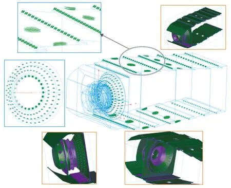
Fig.4 Calculation grid图4 计算网格
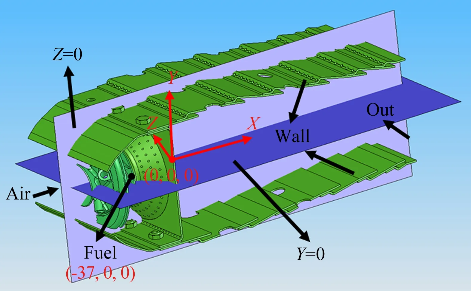
Fig.5 Boundary condition图5 边界条件
4 Results
4.1Experimentalresults
A large number of liquid droplets are formed rapidly due to the atomization process under the action of the nozzle.Fig.6 and Fig.7 show the Sauter mean diameter distributions of the atomized particles along theXaxis in the plane ofY=0 andZ=0,respectively.As shown in the figure,the Sauter mean diameter of liquid particles is distributed uniformly in the horizontal direction at high temperature and high pressure,and it is approximately equal to 12μm.But there is a slight fluctuation in the vertical direction of the jet,the Sauter mean diameter of liquid particles ranging from 12.6μm to 16.1μm.Obviously,the atomization uniformity in the vertical direction is inferior to the droplet diameter distribution in the horizontal direction.Fig.8 and Fig.9 show that the Sauter mean diameter of particles in the cross section ofX=31.5mm vary along theYdirection and theZdirection,respectively.From the distribution trend in the figure,it can be seen that the diameter distribution of the ato-mized particles is uniform even in theYdirection or theZdirection,the average diameter of most droplet particles in different positions are between 10μm and 15μm,and the symmetry in theYdirection is somewhat worse than that inZdirection.
4.2Simulationresultsanddiscussion
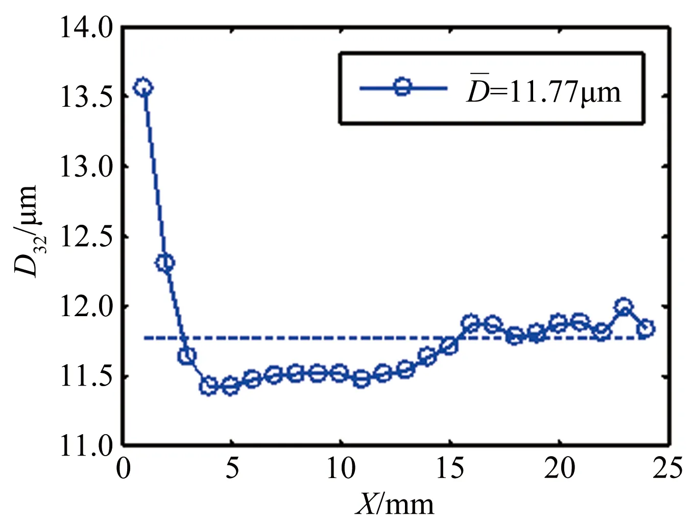
Fig.6 The Sauter mean diameter distribution of droplets along X axis (Y=0mm)图6 Y=0平面上液滴索太尔平均直径沿X轴分布
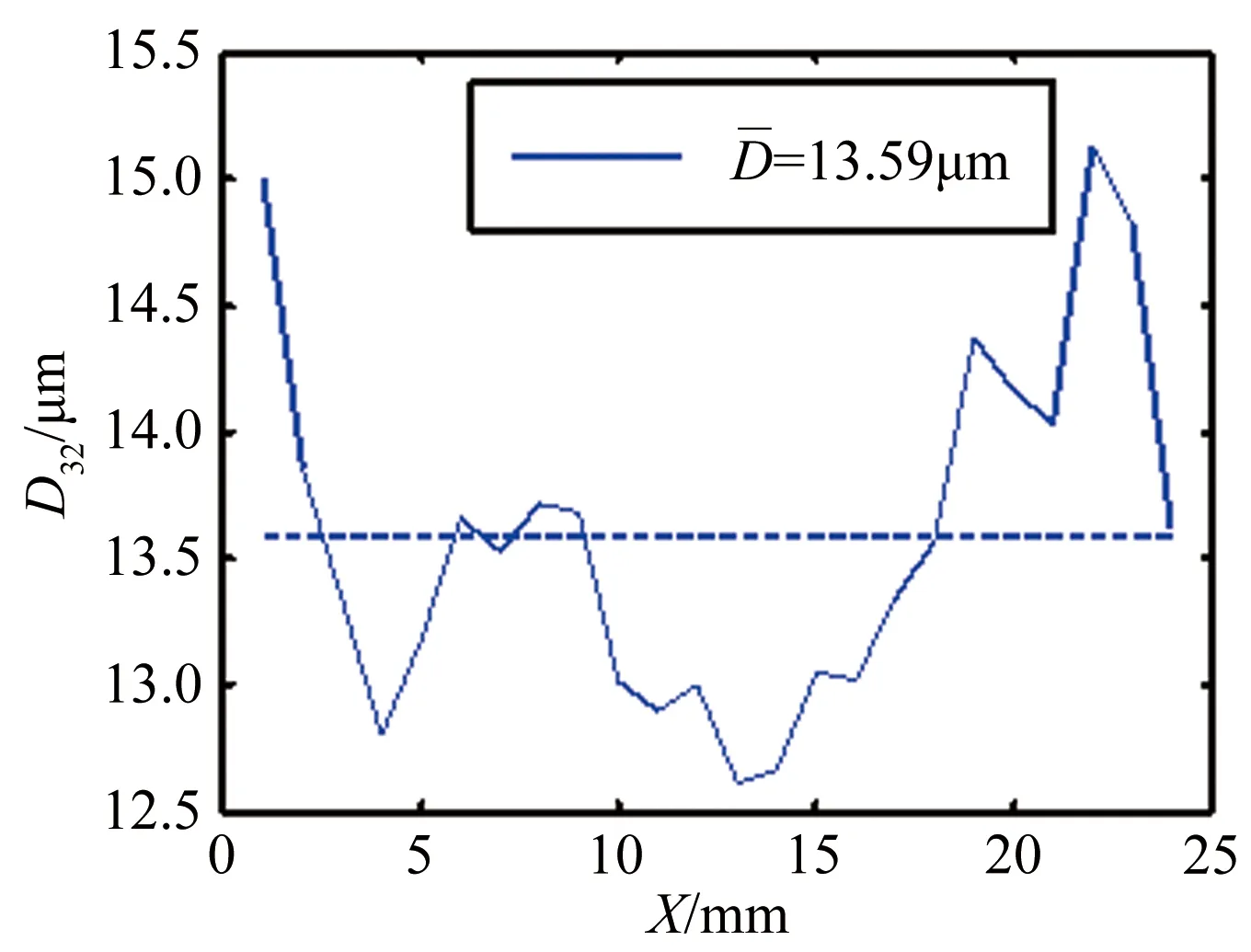
Fig.7 The Sauter mean diameter distribution of droplets along X axis (Z=0mm )图7 Z=0平面上液滴索太尔平均直径沿X轴分布
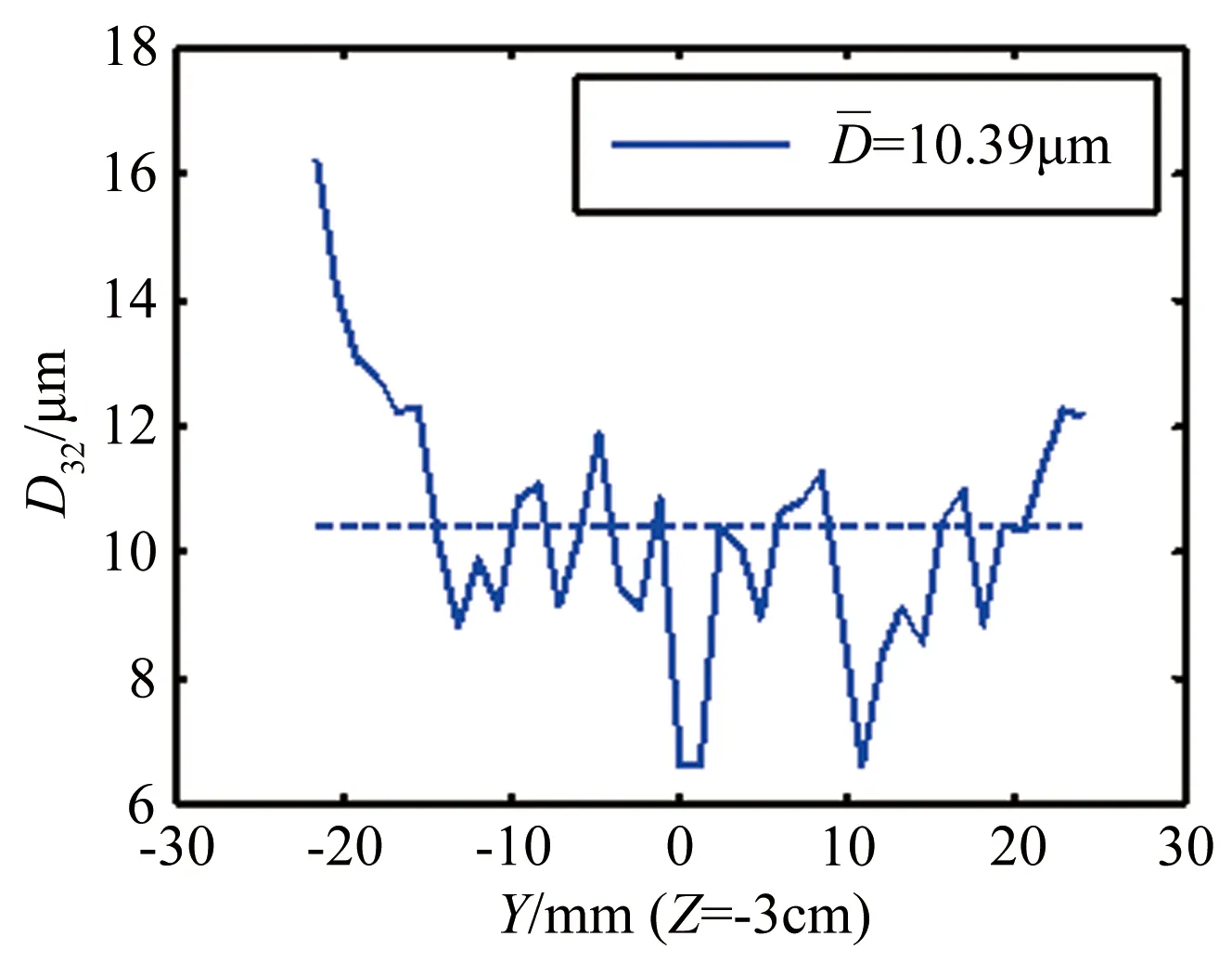
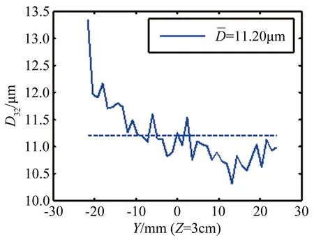
Fig.8 The Sauter mean diameter distribution of droplets along Y axis (X=31.5mm)图8 X=31.5mm平面上液滴索太尔平均直径沿Y轴分布
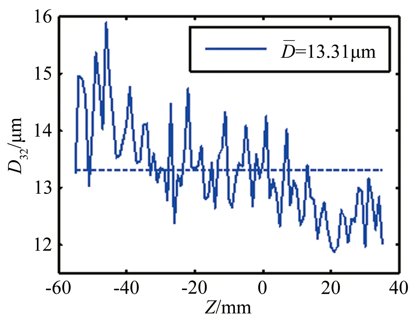
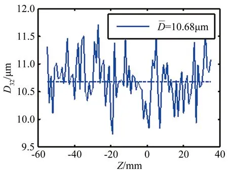
Fig.9 The Sauter mean diameter distribution of droplets along Z axis (X=31.5mm )图9 X=31.5mm平面上液滴索太尔平均直径沿Z轴分布
Fig.10 shows the atomization structure of fuel sprays in the combustor.As shown in the figure,the fuel is injected from the swirl nozzle and expanded into a hollow cone with the form of liquid film.In the Lagrange model,liquid films are replaced by liquid particles in discrete phase,and the detailed description will be introduced later.The large droplets formed by the breakup of liquid film continue to break into small droplets under the action of air flow.As shown in Fig.10,the small droplets are heated in the airflow,and most of the droplets have evaporated before they reach primary jet holes.In Fig.11,the kerosene droplets are divided into 2 ca-tegories.As shown in the figure,kerosene droplets form a fuel torch under the action of swirling flow and move downstream through the primary jets.At the same time,due to the effect of the recirculation zone,a large number of droplets are sucked into the recirculation zone and then move upstream.
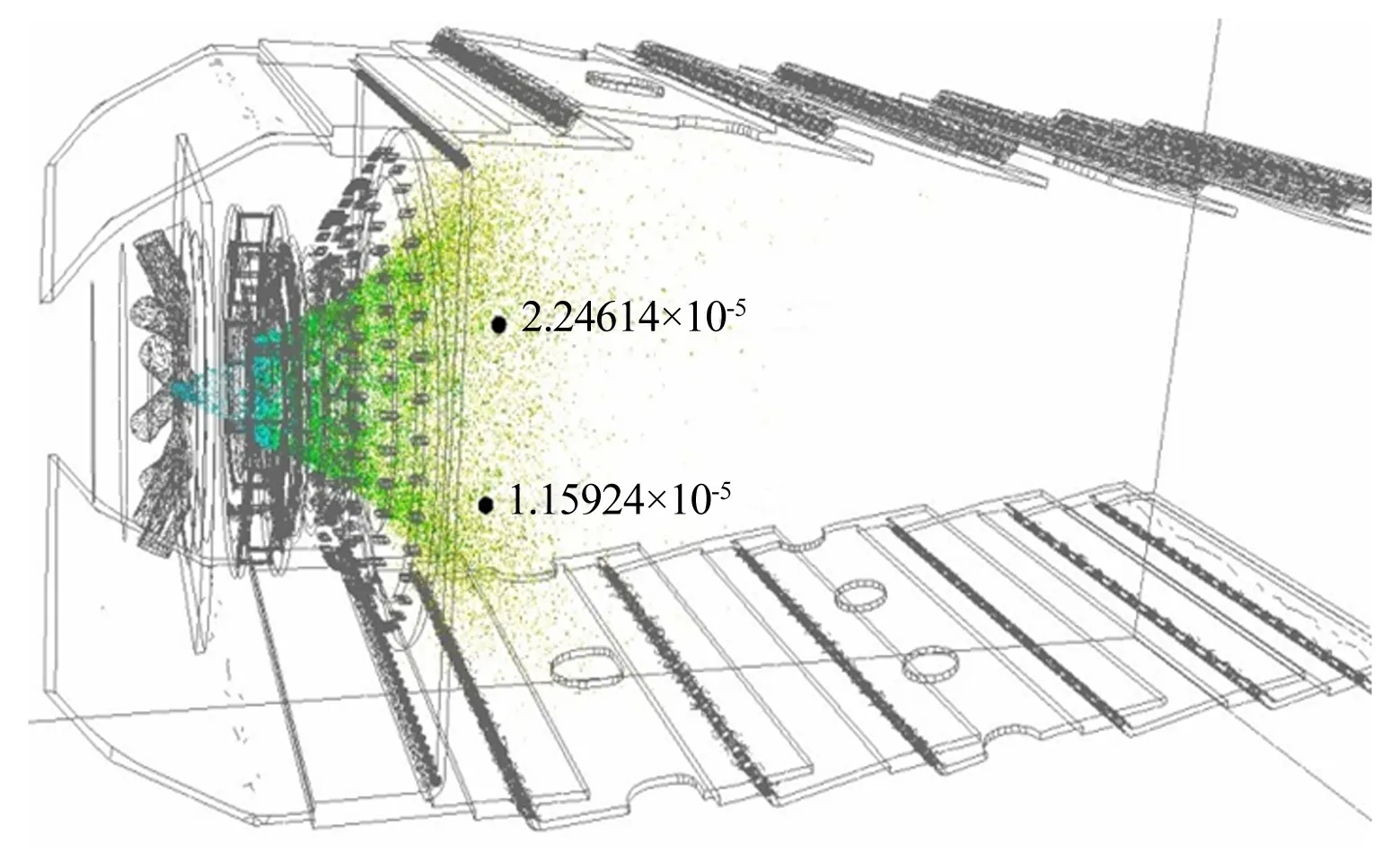
Fig.10 Spray structure图10 喷雾结构
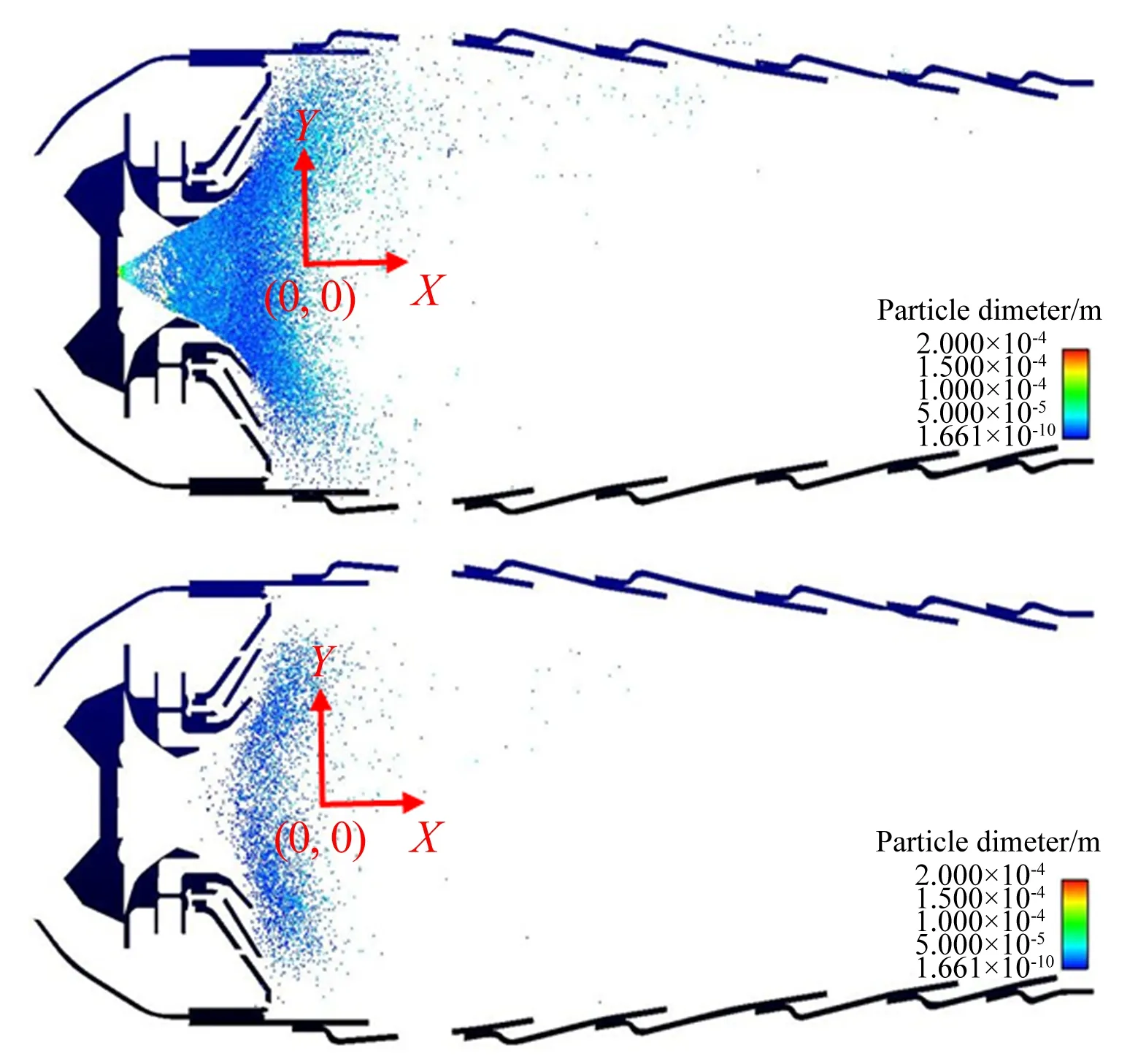
Fig.11 Classification of kerosene droplets in cold flow图11 冷流状态下燃油液滴分类显示
Fig.12 and Fig.13 show the comparisons between simulation results and experimental data of the Sauter mean diameter distributions of droplets in different positions along theXaxis in theY=0 plane and in theZ=0 plane respectively.Liquid film is formed after fuel leaving the nozzle,then the films are teared into liquid ligaments or large droplets,and then the large droplets are further subjected to secondary breakup under the action of a strong swirling flow.Because of the large number of droplets in the flow field,it is impossible to track each droplets during the simulation.So,a discrete element method is adopted,and the identical droplet particles are replaced with a certain amount of particle samples.Fig.12 and Fig.13 show that the liquid droplets diameter in the flow field are generally distributed exceeding 20μm.Fig.12 shows the Sauter mean diameter of the droplets atZ=-1cm andZ=-2cm.Obviouly,the Sauter mean diameter of the droplets obtained from simulation is about 30μm and the corresponding diameter obtained from the experiment is approximately equal to 10μm.Fig.13 shows the Sauter mean diameter of the droplets atZ=-0.48cm andZ=-0.96cm.The comparisons between the experiment and the simulation are the same as that shown in the Fig.12.Compared with Fig.12,the number of particles sample is less in Fig.13,and the diameter in the plane is about 20μm.The atomization and evaporation processes of the fuel in high temperture and high pressure environment of the aeroengine combustor are extremely complicated.Up to now,because of the complexity of atomization mechanism and the environment of high temperature and pressure,the study of fuel atomization in aeroengine is extremely difficult,so the experimental measurement and numerical simulation of the fuel atomization of the real aeroengine combustor are rarely reported in the public literature.In this paper,the Sauter mean diameter of the fuel particles obtained by the simulation is between 20μm and 30μm,the diameter in theY=0 plane is larger than that in theZ=0 plane obviously,and the experimental results is about 13μm.To a certain extent the simulation results are in good agreement with the experimental results,which shows the atomization model adopted in the paper can capture the spray characteristics under the conditions of high temperature,high pressure and strong swirl in aeroengine combustor.
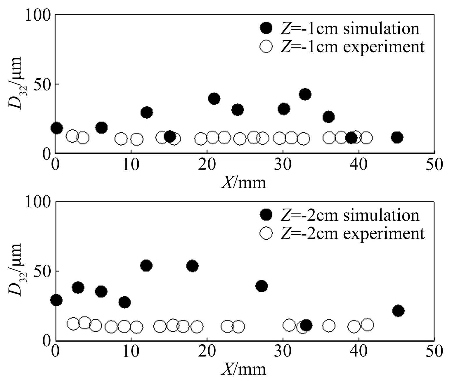
Fig.12 The Sauter mean diameter distribution of droplets in Y=0 Plane图12 Y=0平面内燃油液滴的索太尔平均直径分布
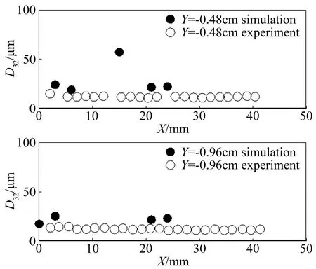
Fig.13 The Sauter mean diameter distribution of droplets in Z=0 Plane图13 Z=0平面内燃油液滴的索太尔平均直径分布
5 Conclusions
The spray field in aeroengine combustor is measured with the particle field pulsed laser holo-graphy imaging technique,and the spray characteristics in combustor under the force of swirling gas are obtained.The Sauter mean diameter of liquid droplets was measured at the exit of the swirler,and the mean diameter is about 13μm.At the same time,the experiment was studied numerically using the developed atomization numerical model,and the spray structure in the combustor was simulated.Based on the simulation results,the Sauter mean diameter of droplets was calculated,and the mean diameter is between 20μm and 30μm.The comparison between the simulation results and the experiment results indicates that the atomization model developed in this work can capture the atomization process of the fuel in the combustor.
[1]Leong M Y,McDonell V C.Mixing of an irblast atomized fuel spray injected into a crossflow of air[R].NASA/CR-2000-210467.
[2]Jun C,Jeng S M.The structure of a swirl-stabilized reacting spray issued from an axial swirler[C].43rd AIAA Aerospace Sciences Meeting &Exhibit 10-13 January 2005 / Reno,Nevada.
[3]Batarseh F Z M.Spray generated by an airblast atomizer:atomization,propagation and aerodynamic instability[D].Darmstadt:Technische Universitat Darmstadt,Doktor-Ingenieurs ,2008.
[4]Zhang Z.Experimental study on fuel spray characteristics in model combustor[D].Nanjing:Nanjing University of Aeronautics and Astronautics,2009.
[5]Xu R,Zhao J X,Yan Y W.Fuel spray characteristic of TAPS/MLDI low emission combustor[J].Journal of Aerospace Power,2012,27(11):2421-2428.
[6]Deng Y H,Zhu J W,Yan Y W.Cold flow field and fuel spray charactersitic of LPP low emission combustor[J].Journal of Nanjing University of Aeronautics &Astronautics,2013,45(2):162-169.
[7]Jaegle F,Senoner J M.Eulerian and Lagrangian spray simulations of an aeronautical multipoint injector[J].Proceedings of the Combustion Institute,2011,33(2):2099-2107.
[8]Hideki M,Ryoichi K.Large-eddy simulation of turbulent spray combustion in a subscale aircraft jet engine combustor—predictions of NO and soot concentrations[J].Journal of Engineering for Gas Turbines and Power,2013,135:1043-1052.
[9]Anthony C,Jeffery P.Comparing spray characteristics from Reynolds Averaged Navier-Stokes (RANS) National Combustion Code (NCC) calculations against experimental data for a turbulent reacting flow[R].AIAA-2010-578,2010.
[10]Cai W X.Research on numerical simulation of two-phase reacting flow field and combustion performance of annular combustors[D].Nanjing:Nanjing University of Aeronautics and Astronautics,2007.
[11]Yan Y W,Song S W,Hu H S.Numerical investigations of two-phase spray combustion flow fields in slinger annular combustor[J].Journal of Aerospace Power,2011,26(5):1003-1010.
[12]Senecal P K,Schmidt D P.Modeling high-speed viscous liquid sheet atomization[J].International Journal of Multiphase Flow,1999,25(6-7):1073-1097.
[13]Schmidt D P,Nouar I.Pressure-swirl atomization in the near field[R].SAE Technical Paper,1999-01-0496.
[14]Lichtarowicz A K,Duggins R K,Markland E.Discharge coefficients for incompressible non-cavitating flow through long orifices[J].Journal of Mechanical Engineering Science,1965:561-580.
[15]Reitz R D,Diwakar R.Structure of high-pressure fuel sprays[R].SAE Technical Paper Series 870598,1987.
[16]Reitz R D.Modeling atomization processes in high-pressure vaporizing sprays[J].Atomisation and Spray Technology,1987,3:309-337.
[17]Patterson M A,Reitz R D.Modeling the effects of fuel spray characteristics on diesel engine combustion and emission[R].SAE Technical Paper 980131,Detroit,1998.

LiuRichao(1986-),male,born in Qingtian Zhejiang province,doctoral candidate.Engaged in combustion and flow in aero-engine research.Address:Xinduhui Ⅱ-806,Beijiao town,Shunde district,Foshan City,Guangdong Province(528311).E-mail:lrc19860517@ sina.cn
(编辑:李金勇)
双旋流燃烧室两相喷雾试验和数值研究
刘日超1,*,乐嘉陵2,陈柳君2,杨顺华2,宋文艳1
(1.西北工业大学 动力与能源学院,西安 710072;2.中国空气动力研究与发展中心超高速空气动力研究所 高超声速冲压发动机技术国防科技重点实验室,四川 绵阳 621000)
采用粒子场脉冲激光全息技术对航空发动机燃烧室中的雾化场进行了测量,得到了燃烧室中燃油液滴直径的空间分布,从而对燃烧室中的雾化过程进行了研究。自主开发完成了适用于航空发动机燃烧室的三维两相数值计算平台,建立了首次雾化模型和二次雾化模型。基于LISA模型和KH-RT模型,对燃烧室中的首次雾化过程和二次雾化过程进行了数值模拟,得到了燃烧室中液雾的空间分布。通过将计算结果与试验结果进行对比,显示开发完成的雾化模型能很好的模拟高温高压,强旋流条件下航空发动机燃烧室的整个喷雾雾化过程。
航空发动机燃烧室;粒子场脉冲激光全息技术;首次雾化;二次雾化
V231.3
A
1672-9897(2017)05-0024-09
LiuRC,LeJL,ChenLJ,etal.Experimentalandnumericalstudyonsprayatomizationinadouble-swirlercombustor.JournalofExperimentsinFluidMechanics,2017,31(5):24-31,45.刘日超,乐嘉陵,陈柳君,等.双旋流燃烧室两相喷雾试验和数值研究.实验流体力学,2017,31(5):24-31,45.
date:2017-07-05;Reviseddate2017-09-26
Supported by NSFC(91641205)
*Corresponding Author E-mail:lrc19860517@sina.cn
Authorbiography
10.11729/syltlx20170093