Experimental and simulation study of aeroengine combustor based on CARS technology and UFPV approach
2017-11-07XiongMoyouLeJialingHuangYuanSongWenyanYangShunhuaZhengZhonghua
Xiong Moyou,Le Jialing,Huang Yuan,Song Wenyan,Yang Shunhua,Zheng Zhonghua
(1.School of Power and Energy,Northwestern Polytechnical University,Xi’an 710072,China;2.Science and Technology on Scramjet Laboratory of Hypervelocity Aerodynamics Institute,China Aerodynamics Research and Development Center,Mianyang Sichuan 621000,China)
ExperimentalandsimulationstudyofaeroenginecombustorbasedonCARStechnologyandUFPVapproach
Xiong Moyou1,*,Le Jialing2,Huang Yuan2,Song Wenyan1,Yang Shunhua2,Zheng Zhonghua2
(1.School of Power and Energy,Northwestern Polytechnical University,Xi’an 710072,China;2.Science and Technology on Scramjet Laboratory of Hypervelocity Aerodynamics Institute,China Aerodynamics Research and Development Center,Mianyang Sichuan 621000,China)
Based on the Unsteady Reynolds Averaged Navier Stokes(URANS) method,a three-dimensional two-phase turbulent combustion numerical software for aeroengine combustor has been developed.The physical and chemical processes taking place in the liquid fuel are simulated completely,including liquid film formation,breakup,evaporation and combustion.LISA and KH-RT are used as the primary and second atomization model respectively,and also the standard evaporation model is used to simulate the evaporation process.Besides,detailed chemical mechanism of kerosene is used for reaction kinetics,and the Unsteady Flamelet/Progress Variable (UFPV) approach in which the unstable combustion characteristics of the flame could be simulated is used as the combustion model.The temperature and species of the flow field and the diameter of fuel droplets in the aeroengine combustor are obtained.At the same time,the Coherent Anti-stokes Raman Scattering (CARS) technology is used to measure the temperature in the primary zone of the aeroengine combustor.Then the temperature of the simulation is compared with that measured by CARS technology,and the calculation error of numerical results is less than 7.3%.The studies have shown that the numerical method in this paper and UFPV approach can simulate the two-phase turbulent combustion process appropriately in the aeroengine combustor.
aeroengine combustor;two-phase combustion;UFPV approach;CARS technology
0 Introduction
As the demands for the new generation aeroengine increase,higher requirements are put for the combustor,including combustion efficiency,outlet temperature distribution,combustion stability,emissions,ignition/blowout limits,and so on[1].The studies of the new combustion organization,chemical reaction,and the interaction between turbulence and combustion are carried out.The aviation kerosene is a macromolecular hydrocarbon fuel.During its combustion process,thousands of elementary reactions take place in the combustor.The combustion mode is a coexistence of the non-premixed and premixed combustion[2-5],and thus the combustion processes are quite complicated.Numerical simulation is one of the important methods in the study of combustion mechanism and aeroengine combustor design,and the combustion model is a key technical problem in the numerical simulation.
At present,the majority studies of the numerical simulation about turbulent combustion in aeroengine combustor adopt simplified combustion models.Some disadvantages of these models are as follows:there are too many assumptions,and more assumptions lead to worse accuracy.These combustion models ignore the interaction between the turbulence and chemical reactions,and detailed chemical reaction kinetics can not be simulated.Additionally,the calculation efficiency is low,the processes of calculation are complex,intensive and expensive.As a result,they are not suitable for practical engineering applications.It is especially important to develop a combustion model that is applicable to the numerical simulation of aeroengine combustor at present and in the future.
Peters[6-7]has first proposed a steady laminar flamelet model,referred to SLFM,in which mixture fraction is used as an independent variable to solve the flamelet equation,and the mixture fraction is used to describe the mixing process of the fuel and the oxidant in combustion.The model has been used widely lately.Owing to the unstable characte-ristics of local extinguishing and reigniting of turbulent combustion,Pierce and Moin[8-9]proposed a steady flamelet/progress variable approach on the basis of SLFM,referred to as SFPV,which replaces the scalar dissipation rate in the SLFM with the progress variable,and it could represent the intermediate process of the local extinguishing,thus some unstable properties of the turbulent combustion,such as local extinguishing and reigniting phenomenon can be captured correctly.According to the results of DNS early,Pitsch and Ihme[10]first found that the steady flamelet library could not capture the unsteady structure of the flame,because the transient process of the local extinguishing and reigniting of the actual turbulent combustion is far from the steady combustion state,so unsteady flamelet/progress variable approach,referred to as UFPV was proposed based on SFPV by Pierce,and then it was studied and verified systematically in doctoral thesis by Sadasivuni[11],and the lift-off height of partially premixed flame was calculated accurately with the UFPV approach and LES.Auto-ignition process of methane/air lifted flame was studied by Ihme and See[12],who found that the traditional combustion model based on the steady combustion can not simulate the variation of the thermodynamic scalar parameter in space-time during the transient ignition process.Auto-ignition process of the lifted flame in the diesel engine was simulated using the UFPV approach based on RANS by Bajaj[13],and the combustion model was proved more efficient than the finite rate model which solves the multi-step chemical reaction directly in the flow field[14-15].Based on RANS,the UFPV approach was used to simulate the lifted flame by Naud and Novella[16],and the numerical simulation results are in good agreement with the experimental data.
The temperature and pressure are high,and meanwhile the turbulence is strong in the aeroengine combustor.The true combustion process is to be understood urgently.As a result,the temperature is to be measured correctly with the optical measurement technology,and CARS is an advanced measurement,and the measurement of the temperature in the primary zone with CARS technology is necessary.
Based on the above statement,the UFPV approach has not been used to simulate the aero-engine combustor currently.For the reason,the UFPV approach combined with liquid atomization evaporation models is used to simulate the true turbulent combustion of the liquid kerosene in the aeroengine combustor,and the numerical results are compared with the measured temperature by CARS technology so as to provide the basis for the design and evaluation of aeroengine combustor.
1 Physical and mathematical models
1.1Transportequationsofmixturefractionandmixturefractionvariance


1.2Transportequationofprogressvariable
In the UFPV approach,the progress variable represents the degree of reaction,and there is a one-to-one correspondence between the degree of the reaction and the progress variable,so it must be a non-conserved quantity when defining the progress variable.Linear combination of the mass fraction of the species is adopted usually.The sum of the mass fraction of carbon dioxide,carbon monoxide,water and hydrogen is used to define the progress variable in this paper.
The corresponding source term for the equation of progress variable is defined as:
The transport equation of the progress variable is as follows:

1.3Flameletequations
By the coordinate transformation,the space coordinates of the species equations and the energy equation are replaced by the mixed fractionf,which can be obtained by the unsteady flamelet equations(6) and (7)[17],as follows:

The unsteady laminar flamelet libraryφ(f,C,χst) is obtained by means of the chemical reaction kinetics and unsteady flamelet equation(6) and (7) and detailed chemical kinetics of kerosene in this paper.
Turbulent flamelet library is obtained by the way of integrating the probability density function with the laminar flamelet library:


The size of turbulent flamelet library about UFPV approach is 100×50×12×28 here.
1.4Atomizationmodel
The whole breakup and evaporation process of fuel particles is considered,LISA model[18-19]is used to simulate the primary atomization of liquid fuel,KH-RT model[20]is used for secondary breakup,and standard evaporation model is used for simulating the evaporation of fuel particles.Detailed description about atomization model is given in Ref.[18-20].
2 Experimental and numerical settings
2.1Studyobjectsandflowconditions
The study object is a model combustor,as shown in Fig.1.The air flows in theXdirection,and the vertical direction of the primary air jet holes are in theYdirection,and the lateral flow is in theZdirection.The liquid kerosene is injected from the fuel inlet through the swirl atomizer nozzle into the combustor,and turbulent flame is formed when the fuel steam and the air flow are mixed after atomization and vaporization.The burnt mixing gas interacts with the fresh air from primary air jet holes,diluted air jet holes and air film holes,and then flows out from the combustor exit.
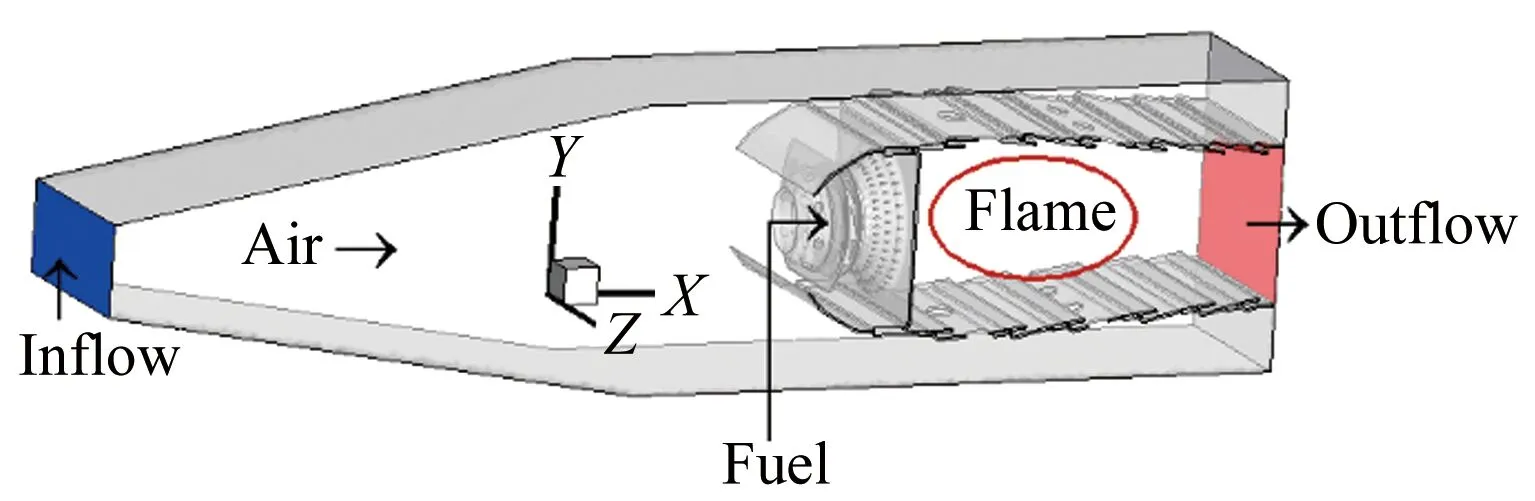
Fig.1 Schematic diagram for aeroengine combustor图1 航空发动机燃烧室构型
Due to experimental limitations,the experimental condition is a reduced pressure model state.As shown in Fig.1,the air flow rate from “Inflow” to the combustor is 0.44kg/s,and the temperature and the pressure are 861K and 0.55MPa respectively.The flow rate of the liquid kerosene from “Fuel” into the combustor is 0.0115kg/s,and the temperature is 300K.The calculated side wall boundary condition is also wall,which is the same with the experiment.Moreover,k-εtwo-equation model is used as the turbulent model in simulation,and detailed chemical reaction mechanism of the kerosene is used for kinetics.Then 203 species are included in the chemical reaction mechanism.In this paper,the boundary conditions of experimental measurements and numerical simulation are shown in Table 1.
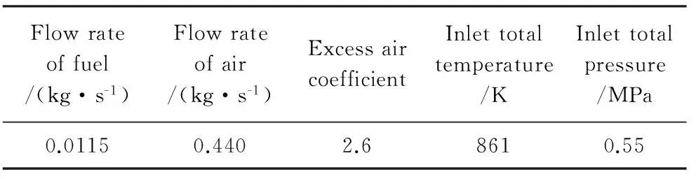
Table 1 Boundary inlet condition of combustor表1 燃烧室边界条件
2.2Experimentalplatformandmeasurementmethod
Fig.2 is a photograph of the aeroengine combustor measuring platform.The experimental system mainly includes resistance heater,high pressure air source,fuel supply system,test control,data acquisition system and aeroengine combustor.Using resistance heater to heat the air is the main feature of the measuring platform.Compared to the pollution air by combustion,it provides clean and dry air for the entrance of combustor.

Fig.2 Photograph of the aeroengine combustor measuring platform图2 航空发动机燃烧室测量平台照片
Fig.3 shows a photograph of model combustor.To measure the temperature in the primary zone of the combustor,rectangular windows of 0.1m length and 0.08m width are placed on each side in the primary zone,and quartz glass and sealed material are used for filling and sealing.

Fig.3 Photograph of model combustor图3 模型燃烧室实物照片
CARS is used to measure the temperature of the primary zone in the combustor.A pump and a broadband Stokes beam are selected on the basis of measuring molecular Raman displacement,and the non-linear effect resonance CARS signal is formed by the way of phase matching approach focuses on the combustion flame zone and measured molecules.The linear profile of the CARS signal spectrum is related to the temperature,species concentration and pressure of the measured medium.When the concentration of the detected species is greater than 30% and the pressure is constant,the line profile of the CARS spectrum is determined by temperature.As the hydrocarbon fuel is usually used in the aeroengine combustor,the nitrogen concentration in the combustion field is generally higher than 30%,and nitrogen is chosen as the detected species for temperature measurement.The temperature measurement range of CARS technology is 200~3000K.Fig.4 shows a picture of the CARS test integration system for aeroengine combustor,the system mainly includes laser module,signal receiver module,spectral receiver module,computer controller module and optical fiber.
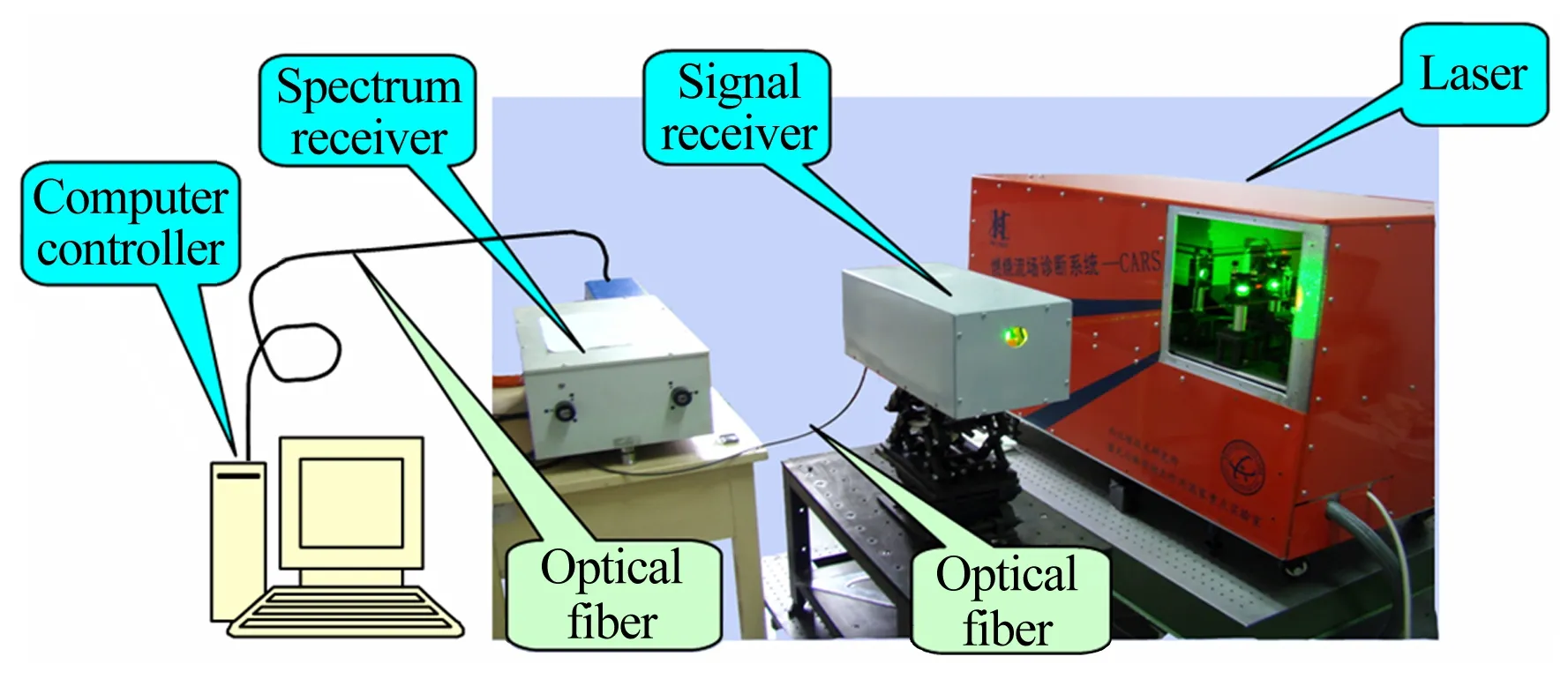
Fig.4 Picture of CARS test integration system for aeroengine combustor图4 CARS测量集成系统
Fig.5 shows the CARS measurement location of temperature in the zone near the primary air jet holes in the combustor.Ten scattered points are measured,and all of these points are in the section of the primary air jet hole in the combustor.
Fig.5 Schematic diagram for CARS measurement location of temperature in the zone near the primary air jet holes图5 航空发动机主燃孔附近CARS测温位置示意图
2.3Numericalsetting
2.3.1Gridofcombustor
Considering the extremely complex configuration of the combustor,the hybrid grid is selected.For example,hexahedral grid is used for the diffuser,and tetrahedral grid is used for inside of swirler.The computational grid completely simulates the true geometry of combustor,and in particular,small structures such as air film holes are not simplified and authenticity of numerical simulation is improved.The grid number of combustor is about 6.21 million,while the local mesh of the wall and primary recirculation zone is locally encrypted,reaching 10-2millimeter magnitude.The grid of combustor is shown in Fig.6.
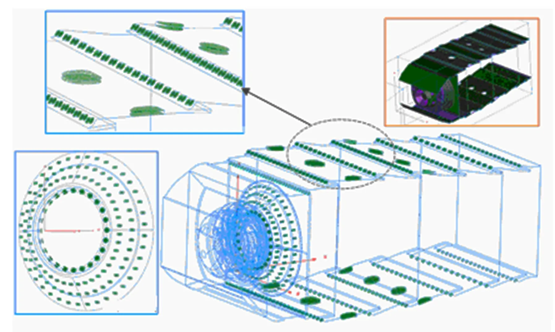
Fig.6 Grid of combustor图6 燃烧室网格划分
2.3.2Generationofflameletlibrary
Fig.7 shows the S curve of the maximum temperature with the variation of the stoichiometric scalar dissipation rate when the flamelet library is generated under the boundary conditions given in Table 1 above.In Fig.7,stable burning branch is the red segment,partial extinguished unsteady burning branch is the blue segment and pure mixing limit branch is brown segment.Each green point corresponds to an unsteady flamelet.All unsteady flamelets are used to generate flamelet library of UFPV approach.
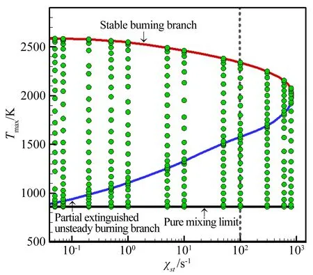
Fig.7 S curve of the maximum temperature with the variation of the stoichiometric scalar dissipation rate图7 最大温度随当量标量耗散率变化的S型曲线
Fig.8 is the temperatureTdistribution in the mixture fraction space when the stoichiometric scalar dissipation rate is 100s-1.Each line corresponds to a transient laminar flamelet.The black line at bottom is referred to “T-extinguish”,which are extinguished flamelets.The red upper line is referred to “T-stable”,which are stable burning flamelets.The middle blue line is referred to “T-unstable”,which are partial extinguished unsteady burning flamelets.And all the flamelets between “T-extinguish” and “T-stable” are the laminar unsteady flamelets in transient state.
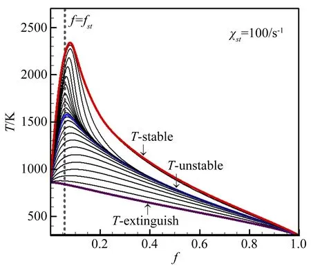
Fig.8 Distribution of temperature T in the mixture fraction space when the stoichiometric scalar dissipation rate is 100s-1图8 当量标量耗散率为100s-1时,温度在混合分数空间的分布
3 Experimental and numerical results
3.1Comparisonstudyofexperimentandnumericalsimulation
Table 2 shows the temperature of the CARS technology measurements and numerical simulation at the locations in Fig.5.As seen from Table 2,the second column temperature is CARS measured value.Because the points 1,2,7 and 8 are inside the primary high temperature zone,and the chemical reaction is intense and the temperature is high here.The temperature at point 5 and 6 is relatively low due to the low temperature fresh air from primary air jet holes diluting the burnt gas.Overall,the CARS measurement values are consistent with the true combustion characteristics of the primary zone,and it has been proved that the uncertainty of the CARS measured value is less than 4%.
The temperature of the UFPV approach based on the atomization model and measurement temperature of the CARS is in good agreement,and the error is usually within 5%.There is only one point “6”,and the maximum error is up to 7.3%.Therefore it shows the high precision of the UFPV approach combing atomization models to simulate the two-phase turbulent combustion in the combustor,because the combustion model contains a large number of unsteady flamelets,and thus the unsteady effects can be simulated accurately in the zone close to the nozzle.Due to the fact that the measurement uncertainty of the CARS is about 4 percent,overall the simulation values of temperature in this paper are consistent with the CARS measurement results.
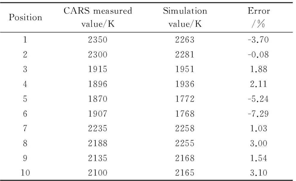
Table 2 Temperature of the CARS technology measurements and numerical simulation表2 数值模拟与CARS测量温度分布结果
3.2Numericalresultsandanalysis
Fig.9 shows that the iso-surface of liquid particle axial velocity is 5m/s (red surface) and -1m/s (blue surface) respectively.Because the distribution of liquid particles is not continuous,the contour distribution of liquid particles velocity is also discontinuous.As a result of the action of the swirler,the liquid phase particles are attached to the combustor wall of the primary zone of the combustor (the red iso-surface in Fig.9 indicates that the axial velocity is positive).Under the action of air in recirculation zone,some of the liquid particles flow back(the blue iso-surface in Fig.9 represents that the axial velocity is negative).
Fig.10 shows that the iso-surface distribution of fuel mass fraction is 0.015.The liquid fuel is vaporized and the gas fuel is gradually formed in around the wall surface of venture.Under the action of swirler,the gas fuel has a spiral motion,then turbulent flame is formed when mixing with air.From the head of the combustor,the fuel flows into the combustor counter clockwise.
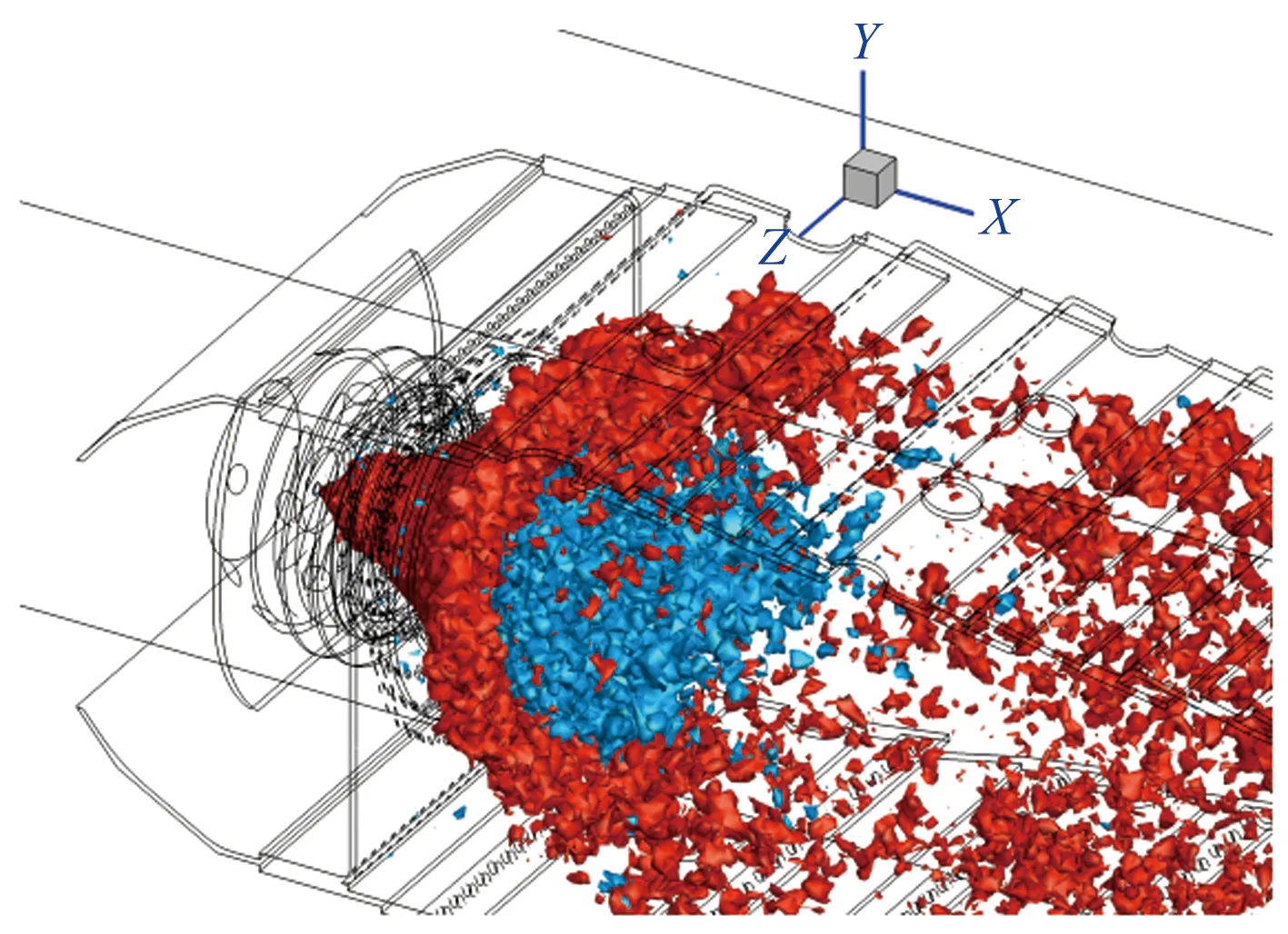
Fig.9 Iso-surface of liquid particle axis velocity is 5m/s (red surface) and -1m/s (blue surface) respectively图9 燃油颗粒速度为5m/s(红色表面)和-1m/s(蓝色表面)的等值面图
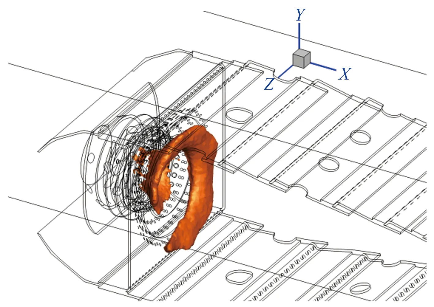
Fig.10 Iso-surface distribution of fuel mass fraction of 0.015图10 燃料质量分数为0.015的等值面图
Two legends are given in Fig.11~12 of the flow field parameters contour distribution.One is the liquid particle diameter,and the other is gas phase flow field parameters,including velocity and mixture fraction.
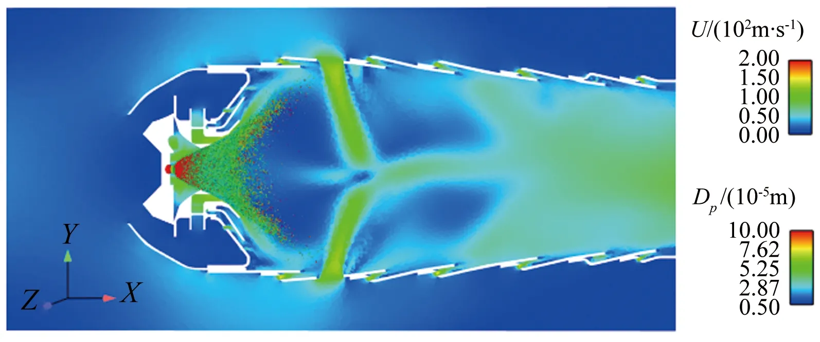
Fig.11 Velocity and diameter of fuel droplets in combustor图11 燃烧室速度及燃油液滴直径分布
Fig.11 shows the velocity of the combustion flow field and the diameter distribution of fuel particles in the liquid phase.The velocity is the sum of the three directions.The velocities at the swirler exit and the primary air jet holes are high,because a large amount of air enters the combustor from the swirler and the primary air jet holes.But the velocity is low in the primary recirculation zone.
Fig.12 shows the mixture fraction of combustion flow field and the diameter distribution of fuel particles in the liquid phase.The value of mixture fraction in primary zone from fuel nozzle to primary air jet holes is high,and it is higher in the rotational shear layer,because there is the evaporation zone of fuel particles.
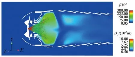
Fig.12 Mixture fraction and diameter of fuel droplets in combustor图12 燃烧室混合分数及燃油液滴直径分布
Fig.13 to Fig.15 show the temperature,progress variable and carbon monoxide mass fraction contour of the two-phase combustion.
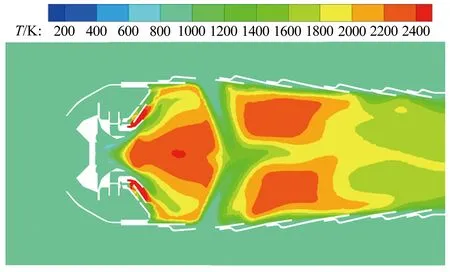
Fig.13 Contour of temperature in combustor图13 燃烧室温度云图
Fig.13 shows the temperature of the two-phase combustion flow field.The high temperature zone is formed in the primary zone where the gas fuel is obtained after breakup and evaporation of liquid fuel.Then turbulent combustion flame is generated when gas fuel and fresh air are mixed.A large area of recirculation is formed in the primary zone,and stable flames are generated by the combustion of fuel in the shear layer near the boundary of recirculation.The burnt gas flows back to the upstream of the recirculation zone,which is a ignition source for the fresh combustible mixture.At the same time,intermediate species,such as carbon monoxide,don’t burn completely in the primary zone,and continue to flow downstream and mix with the fresh air which is from primary air jet holes.As a result,two high temperature zones are formed in the up and down side of combustor axis behind the primary air jet holes.
Fig.14 shows the progress variable of the two-phase combustion flow field.Progress variable is defined with the sum of mass fraction of carbon monoxide,carbon dioxide,water and hydrogen in this paper.According to the definition of the progress variable,it is characterized with the degree of the reaction,so it is noted that from the progress variable in the flow field,it is high in primary zone,and so the degree of reaction in the zone is high and the combustion is intense.In the zone after the primary air jet holes,because of the injection of fresh air from primary air jet holes,intermediate products of incomplete combustion,such as carbon monoxide,continue to burn with fresh air to produce a large amount of final combustion products,carbon dioxide and water.As a result,the value of progress variable is up to 0.33 in this zone.

Fig.14 Contour of progress variable in combustor图14 燃烧室反应进度变量云图
Fig.15 shows the mass fraction of carbon monoxide of the two-phase combustion flow field.As seen from the above analysis,combustion process occurs mainly in the primary zone of combustor,a large amount of fuel vapor is formed in this zone due to the evaporation of fuel particles.Because of a small amount of air from the head of the combustor,rich flame is formed in this zone,and a lot of carbon monoxide is obtained because of combustion is not complete.In Fig.15,carbon monoxide is found in large quantities in the zone.And the rest carbon monoxide flows to the downstream where a plenty of fresh air coming from the primary air jet holes mixes and burns with it.So lean flame is already formed in the secondary zone,as carbon monoxide is depleted further.Therefore there is almost no carbon monoxide at the exit of combustor.
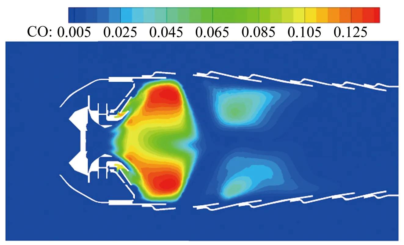
Fig.15 Contour of mass fraction of CO in combustor图15 燃烧室一氧化碳云图
4 Conclusions
Detailed chemical reaction kinetics of the kerosene,the atomization model,the evaporation model and the UFPV approach based on URANS are adopted in this paper,and the three-dimensional two-phase turbulent combustion in the combustor is simulated.At the same time,the temperature of the primary zone in the combustor is measured using the CARS optical technology,and numerical results are compared with the experimental results.The results are as follows:
(1) Scattered temperature of the primary zone in the combustor is measured with the CARS technology,and then comparative study of numerical results and experimental results is conducted.The maximum error between the calculated results and the experimental values is less than 7.3 percent,and the UFPV approach and numerical method adopted in this paper are verified.They are suitable for simulating the turbulent combustion process in combustor.
(2) The combustor is simulated with the UFPV approach and the atomization model.The distribution features of fuel droplet diameter,mass fraction of fuel,velocity,mixture fraction,temperature,progress variables and mass fraction of carbon monoxide are obtained,and the atomization,evaporation and combustion processes of liquid fuel are analyzed.The UFPV approach and numerical calculation method adopted in this paper can provide refe-rence for the design and optimization of the combustor.
[1]Jin J,Liu D H.Recent advances in turbulent two-phase combustion models[J].Journal of Nanjing University of Aeronautics and Astronautics,2016,48(3):304-309.
[2]Legier J P,Poinsot T,Veynante D.Dynamically thickened flame LES model for premixed and non-premixed turbulent combustion[C]//Center for Turbulence Research Proceedings of the Summer Program,2000.
[3]Selle L,Lartigue G,Poinsot T,et al.Large-eddy simulation of turbulent combustion for gas turbines with reduced chemistry[C]//Center for Turbulence Research Proceedings of the Summer Program,2002.
[4]Yang J H,Liu F Q,Mao Y H,et al.A partially premixed combustion model and its validation with the turbulent bunsen flame calulation[J].Journal of Engineering Thermophysics,2012,33(10):1793-1797.
[5]Xiao H H,Shen X B,Sun J H.Experimental study and three-dimensional simulation of premixed hydrogen/air flame propagation in a closed duct[J].International Journal of Hydrogen Energy,2012,37(15):11466-11473.
[6]Peters N.Laminar diffusion flamelet models in non-premixed turbulent combustion[J].Progress in Energy and Combustion Science,1984,10(3):319-339.
[7]Peters N.An asymptotic analysis of nitric oxide formation in turbulent diffusion flames[J].Combust Sci and Tech,2007,19(1-2):39-49.
[8]Pierce C D.Progress-variable approach for large-eddy simulation of turbulent combustion[D].Stanford:Stanford University,2001.
[9]Pierce C D,Moin P.Progress-variable approach for large-eddy simulation of non-premixed turbulent combustion[J].Journal of Fluid Mechanics,2004,(504):73-97.
[10]Pitsch H,Ihme M,Nevada R.An unsteady/flamelet progress variable method for LES of nonpremixed turbulent combustion[R].AIAA-2005-557,2005.
[11]Sadasivuni S K.LES modelling of non-premixed and partially premixed turbulent flames[D].Loughborough:Loughborough University,2009.
[12]Ihme M,See Y C.Prediction of autoignition in a lifted methane/air flame using an UFPV model[J].Combustion and Flame,2010,157(10):1850-1862.
[13]Bajaj C,Ameen M,Abraham J.Evaluation of an unsteady flamelet progress variable model for autoignition and flame lift-off in diesel jets[J].Combustion Science and Technology,2013,185(3):454-472.
[14]Van Oijen J,De Goey L.Modelling of premixed counterflow flames using the flamelet-generated manifold method[J].Combustion Theory and Modelling,2002,6(3):463-478.
[15]Ribert G,Gicquel O,Darabiha N,et al.Tabulation of complex chemistry based on self-similar behavior of laminar premixed flames[J].Combustion and Flame,2006,146(4):649-654.
[16]Naud B,Novella R,Pastor J M,et al.RANS modelling of a lifted H2/N2flame using an unsteady flamelet progress variable apporach with presumed PDF[J].Combustion and Flame,2014,162(4):893-906.
[17]Xing J W.Applications of chemical equilibrium and flamelet model for the numerical simulation of scramjet[D].Mianyang:China Aerodynamics Research and Development Center,2007.
[18]Fung M C,Inthanvong K,Yang W,et al.Experimental and numerical modelling of nasal spray atomisation[C].Ninth International Conference on CFD in the Minerals and Process Industries CSIRO,Melbourne,2012.
[19]Senecal P K,Schmidt D P.Modeling high-speed viscous liquid sheet atomization[J].International Journal of Multiphase Flow,1999,25(6-7):1073-1097.
[20]Reitz R D.Modeling atomization processes in high pressure vaporizing sprays[J].Atomization Spray Technoology,1987,3(309):309-337.

XiongMoyou(1987-),male,born in Qijiang county,Chongqing city,doctoral candidate.Engaged in combustion and flow in aero-engine research.Address:School of Power and Energy,Northwestern Polytechnical University(710072).E-mail:xmy19870102@126.com
(编辑:李金勇)
采用CARS试验技术与UFPV数值方法研究航空发动机燃烧室
熊模友1,*,乐嘉陵2,黄 渊2,宋文艳1,杨顺华2,郑忠华2
(1.西北工业大学 动力与能源学院,西安 710072;2.中国空气动力研究与发展中心超高速空气动力研究所 高超声速冲压发动机技术重点实验室,四川 绵阳 621000)
在自主开发的软件平台上,采用基于URANS的方法计算航空发动机燃烧室的三维两相燃烧流动,考虑了液态燃油从液膜-液滴-燃气-燃烧的完整物理化学过程。其中,颗粒相采用LISA一次破碎模型,KH-RT二次破碎模型和标准的蒸发模型,湍流燃烧模型采用可以考虑非稳态燃烧特性的非稳态火焰面/反应进度变量方法,得到了航空发动机燃烧室中温度、组分浓度和燃油液滴的颗粒直径分布规律。同时,采用CARS光学手段测量燃烧室主燃区的温度分布,并将数值计算结果与光学试验测量值进行比较,数值计算结果和试验值吻合较好,数值计算误差小于7.3%。说明了本文的数值计算方法和UFPV方法在计算航空发动机燃烧室的两相燃烧流动时具有较高的精度。
航空发动机燃烧室;两相燃烧;UFPV方法;CARS技术
V231.2
A
1672-9897(2017)05-0015-09
XiongMY,LeJL,HuangY,etal.ExperimentalandsimulationstudyofaeroenginecombustorbasedonCARStechnologyandUFPVapproach.JournalofExperimentsinFluidMechanics,2017,31(5):15-23.熊模友,乐嘉陵,黄 渊,等.采用CARS试验技术与UFPV数值方法研究航空发动机燃烧室.实验流体力学,2017,31(5):15-23.
date:2017-07-05;Reviseddate2017-09-28
Supported by NSFC(91641205)
*Corresponding Author E-mail:xmy19870102@126.com
Authorbiography
10.11729/syltlx20170090