大采高工作面沿空掘巷窄煤柱合理尺寸研究
2017-11-06武海平
武海平
(晋中市煤炭规划设计研究院,山西 晋中 030600)
1672-5050(2017)05-0032-04
10.3919/j.cnki.issn1672-5050sxmt.2017.10.008
2017-08-02
武海平(1964-),男,山西寿阳人,本科,工程师,从事井工煤矿采矿专业设计工作。
大采高工作面沿空掘巷窄煤柱合理尺寸研究
武海平
(晋中市煤炭规划设计研究院,山西 晋中 030600)
以某矿3046工作面留设区段窄煤柱为工程背景,采用极限平衡理论、数值模拟、工程实践三种方法分析沿空掘巷窄煤柱合理尺寸。通过极限平衡理论计算得到沿空掘巷窄煤柱宽度为4.83 m~5.64 m。通过FLAC3D分析不同煤柱宽度情况下煤柱应力分布和巷道围岩位移分布规律,综合考虑煤柱垂直应力和围岩应力模拟结果得到沿空掘巷窄煤柱宽度为5 m~6 m。通过现场试验,表明该煤矿柱在锚梁网+锚索联合支护情况下,顶底板移近量为60 mm、两帮移近量为65 mm,合理煤柱宽度为5 m左右。
沿空掘巷;窄煤柱;煤柱宽度;数值模拟
沿空掘巷属于回采巷道布置的一种方式[1],可节约煤炭资源。近年来国内外专家学者对沿空掘巷窄煤柱留设进行深入研究[2-3]。柏建彪等[4]通过数值模拟研究了沿空掘巷窄煤柱的稳定性,张科学[5]对“双U”回采巷道布置中的大煤柱内沿空掘巷窄煤柱留设进行了研究。李学华[6]对沿空掘巷煤柱稳定性因素进行了分析。笔者以某矿3406大采高工作面为工程背景,通过理论分析、数值模拟、工程实践研究沿空掘巷窄煤柱合理尺寸。
1 工程地质概况
某矿3046大采高工作面埋深约200 m,煤层厚度为4.6 m~5.3 m,平均煤厚为5 m。煤层倾角为3°~6°,平均倾角为4.5°。5#煤顶板自下而上依次为泥岩、砂质泥岩、泥岩、细砂岩、粉砂岩,底板以泥岩、砂质泥岩、细砂岩为主。
2 煤柱理论分析
沿空掘巷窄煤柱宽度B计算示意图见图1,计算公式为:
B=X1+X2+X3.
(1)

(2)
X3=(0.15~0.35)(X1+X2).
(3)
式中:B为小煤柱宽度,m;X1为上区段工作面塑性区宽度,m;X2为帮锚杆有效长度,取2.2 m;X3为因煤层厚度较大需增大的煤柱稳定性系数;m为煤层采厚,5 m;A为侧压系数,取0.25;φ0为煤体内摩擦角,20°;k为应力集中系数,取2;C0为煤体内聚力,取1.5 MPa;γ为上覆岩层平均容重,取25 kN/m3;P0为锚杆对巷帮的支护阻力,0.3 MPa。
根据三元煤业实际参数带入上述公式,计算得到三元煤业沿空掘巷煤柱宽度为4.83 m~5.64 m。
3 数值模拟
3.1模型的建立
该模拟3号煤层埋深为200 m左右,3046工作面回风巷道中心线为Y方向,取200 m;倾向为X方向,取150 m。模型水平和垂直方向限制,固定底部,上浮岩层均匀加载竖向载荷5 MPa,工作面采空区自行垮落。其岩石力学参数如表1所示。

表1 煤层顶底板岩石力学参数表
3.2数值模拟结果及分析
回采时煤柱宽度在3 m、4 m、5 m、6 m、7 m五种情况下,煤柱最大垂直应力分别为32 MPa、18 MPa、16 MPa、18 MPa、24 MPa。当煤柱宽度为5 m时,煤柱其他位置垂直应力在8 MPa左右,应力值较小;留设其他煤柱宽度时,其他区域应力偏大。
从留设不同煤柱宽度情况下煤柱的垂直应力可知,从煤柱侧向应力曲线最大垂直应力先增大后减小再增大经验规律可知,留设1 m~3 m煤柱时,煤柱最大垂直应力在增大,留设4 m~6 m时煤柱最大垂直应力先增大后减小,留设6 m~7 m煤柱时煤柱垂直应力增大,说明煤柱增大到5 m左右时,煤柱最大垂直应力处于最小值。
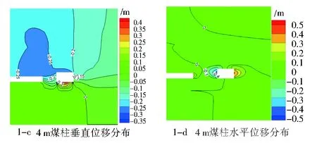
不同煤柱宽度下巷道围岩位移分布图,见图1。


图1 不同煤柱宽度下巷道围岩位移分布图Fig.1 Displacement distributions of surrounding rocks at different width of coal pillars
由图1可知,留设3 m、4 m、5 m、6 m、7 m煤柱时,顶板下沉量分别为330 mm、360 mm、200 mm、195 mm、190 mm;回风巷道外帮最大水平位移分别为500 mm、500 mm、350 mm、350 mm、450 mm。
从回采时不同留设煤柱宽度的煤柱的垂直应力、巷道围岩位移模拟图分析来看,留设3m、4 m煤柱时,垂直应力较大,垂直位移和水平位移较大;留设5 m、6 m垂直应力较小,巷道变形量较小;留设7 m煤柱垂直应力较大,水平位移较大。综上所述留设窄煤柱在5 m~6 m,考虑到增大煤炭回采率,留设窄煤柱宽度为5 m。
4 现场实测
现场支护方案:
1) 顶板支护:①左旋无纵筋螺纹钢筋参数:Φ22 mm×2 200 mm,间排距900 mm×1 000 mm,顶板帮角处锚杆与垂直方向呈10°。②钢筋托梁:Φ14 mm,长4 700 mm,宽90 mm,间距100 mm。③锚索:Φ=28 mm,L=5 000 mm,间排距2 000 mm×2 000 mm,距两帮各1 500 mm。
2) 两帮支护:左旋无纵筋螺纹钢筋参数:Φ22 mm×2 200 mm,间排距1 000 mm×1 000 mm,靠近顶板、底板的锚杆与水平方向呈10°。②钢筋托梁:Φ14 mm,长3 300 mm,宽90 mm。
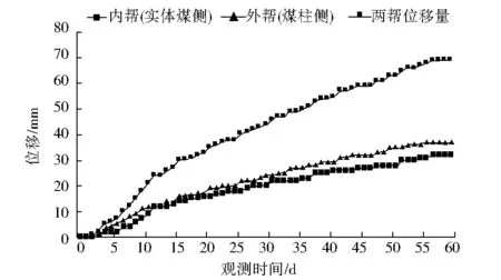
支护后回风巷道围岩变形图,见图2。
回风巷道在掘进10 d~20 d后变形加速,30 d后巷道变形趋于稳定,50 d后巷道变形速度仅为0.4 mm/d。说明在采用留设5 m小煤柱在锚梁网+锚索联合支护下,巷道变形量得到有效控制。

2-a 回风巷道顶底部位移量

2-b 回风巷道顶底板相对位移速度

2-c 回风巷道两帮位移量图2 回风巷道围岩变形图Fig.2 Surrounding rock deformation in air-return roadway
5 结束语
根据极限平衡理论、数值模拟、工程实践方法综合确定该矿沿空掘巷窄煤柱留设为5 m,在锚梁网+锚索联合支护下,留设5 m煤柱稳定性好,巷道变形量得到有效控制。
[1] 杜计平,孟宪锐.采矿学[M].徐州:中国矿业大学出版社,2009.
[2] 贾双春,王家臣,朱建明,等.厚煤层窄煤柱沿空掘巷中煤柱极限核区计算[J].中国矿业,2011,20(12):81-84,102.
JIA Shuangchun,WANG Jiachen,ZHU Jianming,etal.Calculating of the Elastic Central Zone of Narrow Coalpillar along Goaf of Coal Caving in the Thick Coal Seam[J].China Mining Magazine,2011,20(12):81-84,102.
[3] 祁方坤,周跃进,曹正正,等.综放沿空掘巷护巷窄煤柱留设宽度优化设计研究[J].采矿与安全工程学报,2016,33(3):475-480.
QI Fangkun,ZHOU Yuejin,CAO Zhengzheng,etal.Width Optimization of Narrow Coal Pillar of Roadway Driving along Goaf in Fully Mechanized Top Coal Caving Face[J].Journal of Mining & Safety Engineering,2016,33(3):475-480.
[4] 柏建彪,侯朝炯,黄汉富.沿空掘巷窄煤柱稳定性数值模拟研究[J].岩石力学与工程学报,2004,23(20):3475-3479.
BAI Jianbiao,HOU Chaojiong,HUANG Hanfu.Numerical Simulation Study on Stability of Narrow Coal Pillar of Roadway Driving along Goaf[J].Chinese Journal of Rock Mechanics and Engineering,2004,23(20):3475-3479.
[5] 张科学,姜耀东,张正斌,等.大煤柱内沿空掘巷窄煤柱合理宽度的确定[J].采矿与安全工程学报,2014,31(2):255-262,269.
ZHANG Kexue,JIANG Yaodong,ZHANG Zhengbin,etal.Determining the Reasonable Width of Narrow Pillar of Roadway in Gob Entry Driving in the Large Pillar[J].Journal of Mining & Safety Engineering,2014,31(2):255-262,269.
[6] 李学华,鞠明和,贾尚昆,等.沿空掘巷窄煤柱稳定性影响因素及工程应用研究[J].采矿与安全工程学报,2016,33(5):761-769.
LI Xuehua,JU Minghe,JIA Shangkun,etal.Study of Influential Factors on the Stability of Narrow Coal Pillar in Gob-side Entry Driving and its Engineering Application[J].Journal of Mining & Safety Engineering,2016,33(5):761-769.
ReasonableSizeofNarrowCoalPillarsinGob-sideEntryDrivinginLarge-mining-heightWorkingFace
WUHaiping
(JinzhongCoalInstituteofPlanning&Design,Jinzhong030600,China)
Taking narrow coal pillars in 3406 working face as engineering background, limit equilibrium theories, numerical simulation, and engineering practice are used to study the reasonable size of the narrow pillars. According to the limit equilibrium theory, the width of the coal pillars ranges from 4.83m to 5.64m. Stress distribution of the pillars and displacement distribution of the surrounding rocks are studied by FLAC3Dat the different width. Considering the simulation results of the vertical stress of the pillars and the stress of the surrounding rocks, the width of the pillars ranges from 5 to 6m. However, the engineering practice shows that, under the combined support of roof bolting with bar and wire mesh and anchor cables, the reasonable size of coal pillars is around 5 m, with 60mm roof-floor deformation and 65mm two-side deformation.
gob-side entry driving; narrow coal pillars; width of coal pillar; numerical simulation
TD822.3
A
(编辑:杨 鹏)
