Capillary-gravity ship wave patterns *
2017-11-02HuiLiangXiaoboChen
Hui Liang, Xiaobo Chen,2
1. Deepwater Technology Research Centre (DTRC), Bureau Veritas, Singapore,
E-mail: hui.liang@sg.bureauveritas.com
2. College of Shipbuilding Engineering, Harbin Engineering University, Harbin 150001, China
(Received June 6, 2017, Revised July 31, 2017)
Capillary-gravity ship wave patterns*
Hui Liang1, Xiaobo Chen1,2
1. Deepwater Technology Research Centre (DTRC), Bureau Veritas, Singapore,
E-mail: hui.liang@sg.bureauveritas.com
2. College of Shipbuilding Engineering, Harbin Engineering University, Harbin 150001, China
(Received June 6, 2017, Revised July 31, 2017)
Ship wave pattern is a fascinating research topic in the fields of marine hydrodynamics and water waves. Within the pure-gravity wave theory, the ship wave pattern composed of transverse waves and divergent waves appearing on the downstream is confined within a sector symmetrical about the ship track with a half-angle 19o28′. However, when the surface tension is accounted for, the wave pattern is greatly modified especially at a low translating speed. Besides the minimum speed of capillary waves cmin=0.23m/s below which waves cannot be generated, there is another critical speed cdiv=0.45m/s associated with the disappearance of divergent waves. In the present paper, the wave patterns created by a steadily translating source are studied, and they are examined with the crestlines obtained from the asymptotic analysis.
Ship waves, wave pattern, gravity-dominant waves, capillarity-dominant waves
Introduction
When a body (surface piecing or submerged) or a pressure patch steadily translates in calm water,free-surface waves are generated and they are referred to as “Kelvin ship waves”[1]. The Kelvin ship wave pattern composed of transverse waves and divergent waves is confined within a wedgeof half angle equal to 19o28′, and this angle is referred to as“Kelvin capillarity-dominant waves on the upstream. On the downstream,the pattern of gravity-dominant waves is close to the classical pure-gravity ship wavesat a high advancing speed. At a low travelling speed, however,the difference is obvious. A striking feature is that there is a critical speed cmin=0.23m/s belowon the upstream[2].
Furthermore, there is another critical speed cdiv=0.45m/s which was firstly mentioned by Binnie[11]. Features of far-field ship wave patterns across the critical speedcdivhave been investigated recently[7-9]. When the travelling speedis greater than cdiv=0.45m/s, the gravity-dominant wave pattern is composed of three wave systems including: transverse waves, divergent waves and fan waves. At the critical speedcdiv=0.45m/s, divergent waves disappear just right, and transverse waves and fan waves are connected. When the speed is less than cdiv=0.45m/s but greater than cmin=0.23m/s,new transverse-fan wave system[9].
In the present article, the capillary-gravity ship wave patterns generated by a translating source are studied, and numerical examples across the critical angle” which can be expounded by the stationary phase analysis[2].Recently, more sophisticated cases are also considered[3-5].
In the water wave theory, the surface tension effect is usually ignored, because it is only significant to very short waves with wavelength in the order of centimeters[6]. However, the ship wave pattern accounting for the surface tension effect can be totally different from the classical Kelvin ship wave pattern predicted by the pure-gravity wave theory[7-9], and this difference is noted as early as Lamb[10].When the surface tension effect is accounted for, there exist speed cdivare demonstrated. The layout of the paper is as follows. The basic equations are firstly presented.Then, the fundamental solution for the steady capillary-gravity ship wave problem based on the Fourier transform is formulated. Finally, numerical implementations are made to study the features of the wave patterns for different travelling speeds.
1. Basic equations
A frame of reference OXYZ translating with the object at the forwardspeed U in the direction of the positive X-axis is defined with theXY plane coincidingwith the undisturbed free surface and Z-axis orienting positively upwards. Weassume the fluid inviscid, incompressible and flow irrotational so that thevelocity potential exists.
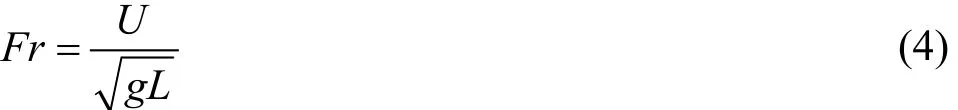
For the sake of simplicity, we define the nondimensional coordinates (x,y,z ), Fourier coordinates(α,β) and velocity potentialφ as following:
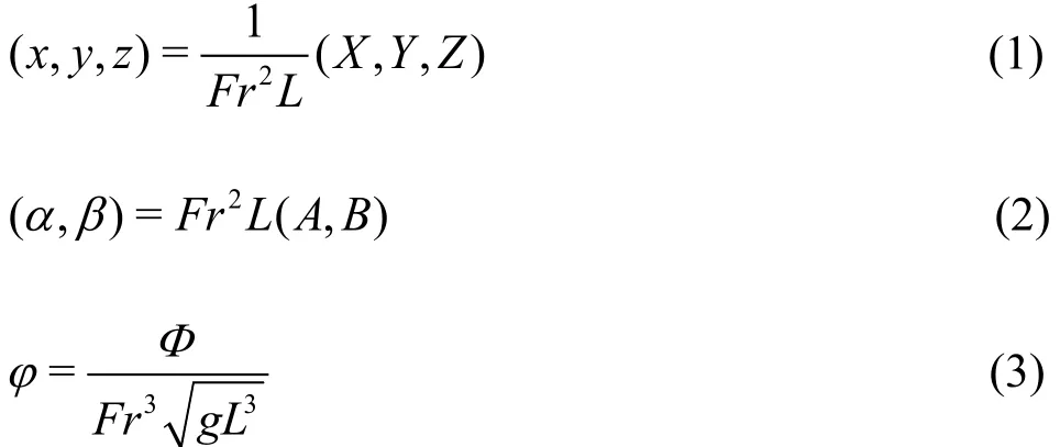
whereL denotes the reference length. In addition,the non-dimensional Froude number Fr associated with the travelling speed is defined as
whereg represents the acceleration of gravity. Then,the linearized free-surface boundary condition in anon-dimensional form is expressed
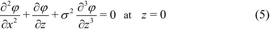
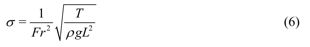
In (5),σ denotes a parameter associated with the surface tension effect which is defined as
2. Fundamental solution
In this section, we are concerned with the fundamental solution to the capillary-gravity ship wave problem, which is also referred to as the capillary-gravity ship wave Green function. The capillary-gravity ship wave Green function is useful in constructing the boundary integral equation which can be used to study the wave-resistance and wave patterns generated by a translating body or a pressure patch. Usually, the expression of Green function takes the form of
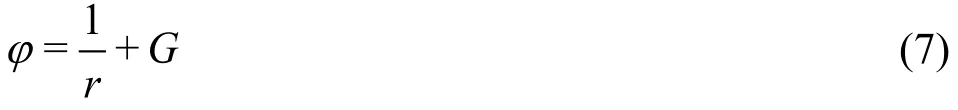
where denotes the distance between the field point(x,y,z ) and the source point (ξ,η,ζ), and the term Gaccounting for the free-surface wavy effect is accompanied to make sure the potential φ satisfies the free-surface boundary condition given by (5). Here,the potentialφ satisfies

whileG is harmonic in the fluid and satisfies the Laplace equation

We suppose that the source point locates on the axis which means that ξ=0 and η=0 without loss of generality. In (7), expression 1/r representing the source potentialin theinfinite fluidcan bewritten in the form of a double Fourier
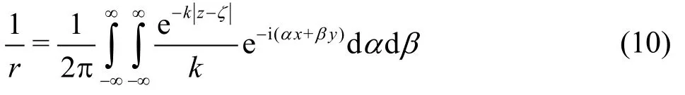
Performing Fourier transform to velocity potential as conducted in Ref.[2] yields
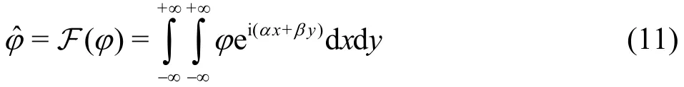
where the operator F denotes the Fourier transform.Its inverse Fourier transform is

Performing the Fourier transform to the free-sur-face boundary condition yields
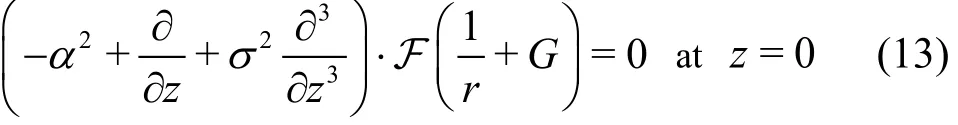
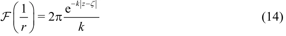
where the Fourier transform of 1/r is expressed as
Recalling the Laplace equation ▽2G=0, its Fourier transform is
Accounting for the fact that the disturbance disappears at a large depth, the solution to (15) is in the form of
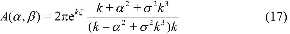
By introducing (14) and (16) into (13), we can obtain the expression of A(α,β)
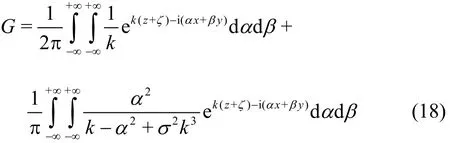
By substituting (17) into (16) and performing inverse Fourier transform as conducted in (12), we can obtain the expression of G
As a consequence, the capillary-gravity ship wave Green function is written as
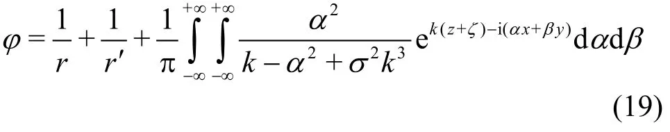
In (19),r′ represents the distance between the field point and the mirror source point above the free surface. The first two terms on the right-hand side of(19) are often called Rankine part of Green function.An equivalent expression of φ with 1/r - 1/r′ as the Rankine part is usually given in the case of pure-gravity ship waves. We prefer (19) here since the integrand in the double Fourier integral behaves as O (1 /k) ask→∞.
By converting the Cartesian Fourier coordinates to polar Fourier coordinates, representation (19) becomes
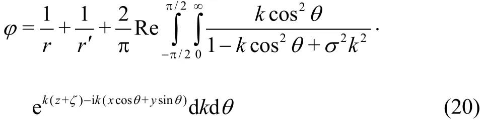
We define the denominator of the integrand in above double Fourier integral as dispersion function which is associated with the linear free-surface boundary condition (5) and expressed as

The dispersion equation D(α,β)=0 gives two closed dispersion curves symmetrical about axes α=0 and β=0 by:
where kGand kTdenote the gravity-dominant and capillarity-dominant wavenumbers[13], respectively.
The dispersion relation described by these curves ties up with far-field waves. As described in Ref.[14],the close relationship reveals that kinematic behaviours including phase and group velocities, crestlines,cusp angles, etc can be determined by the geometrical property of dispersion curves. In Ref.[9], the analysis of the dispersion relation defined by (23) on the Fourier plane has been carried out. For pure-gravity ship waves, there are also two dispersion curves which are open, i.e., the wavenumber tends to infinity.However, when the surface tension effect is accounted for, the dispersion curves are closed with a minimum wavenumber and a finite maximum wavenumber.Each dispersion curve can be divided intotwo parts[15]:gravity-dominant dispersion part and capillaritydominant dispersion part corresponding to gravitydominant waves and capillarity-dominant waves,respectively. When the travelling speed is equal to the minimum speed of capillary waves cmin=0.23m/s,the dispersion curve reduces to an isolated point at(2,0), which means that far-field waves totally disappear and no wave exists[15].
For the gravity-dominant dispersion curve, according to the asymptotic analysis in Ref.[9], constitution of gravity-dominant wave pattern is determined by the number of inflection points along the gravitydominant dispersion curve. When the speed is greater than cdiv=0.45m/s (or σ<0.133), there are two inflection pointsdividingthegravity-dominant dispersion curve intothreesegmentswhich correspond to transverse waves, divergent waves and fan waves, respectively. At the critical speed cdiv=0.45m/s (or σ=0.133), two inflection points coincide, and the coalesced inflection point divides the gravity-dominant dispersion curve into two segments. In this scenario, divergent waves associated with the segment between two inflection points disappear, and transverse waves and fan waves joint together. When thespeed is less than cdiv=0.45m/s but larger than cmin=0.23m/s(0.133< σ <0.5), there is no inflection point along the gravity-dominant dispersion curve, and transverse waves and divergent waves are merged to the transverse-fan wave system.
Expression (20) represents the capillary-gravity ship wave Green function consisting of the source term (1/r), image source term (1/r′)and the free-surface term (G) expressed by a double Fourier integral which provides the wavy properties. For the efficient and accurate computation of the double Fourier integral in (20), we first of all consider the inner k-integral. Unlike the ship wave Green function ignoring the surface tension effect, there are two poles in the denominator of (20) associated with two characteristic wavenumberskGand kTgiven by (22).

Fig.1 (Color online) Sketch of the integration contours passing by poles kG and kT
In order to identify the integration path passing by the poles given by (22), we introduce a small parameter following the weakly-damped free-surfaceflowto satisfy the radiation condition in the far field. As a consequence, the integration contour passes by the polefrom below while it goes acrossfrom above as depicted in Fig.1. By changing the integration contour on the complex kplane and applying Cauchy's theorem of residue, we can decompose the capillary-gravity ship wave Green function into two parts. One is the wave component in the form of a single integral with respect toθ which is dominant in the far field, and the other one is local component in the form of a double integralwith respect to both k and θ[17].
Furthermore, for the local component in the form of double integral, the integral with respect tok can be represented by the complex exponential-integral function. Finally, the capillary-gravity ship wave Green function can be represented fully by a single integral with respect toθ, and the single integral can be evaluated using the numerical quadrature rule in an efficient and accurate way.
3. Numerical implementations and wave patterns
In the present section, the capillary-gravity ship wave patterns generated by a steadily translating source are studied, and the numerically evaluated wave patternis compared with the far-field crestlines obtained from the asymptotic analysis[9].
In Fig.2, the classical pure-gravity ship wave pattern ignoring the surface tension effect is firstly investigated. On the upper part of Fig.2, the plan view of the free-surface profile induced by a submerged steadily translating source located at (0,0,-0.2) is presented.The wake pattern obviously consists of transverse waves and divergent waves.Both wave systems are confined within a cusp line with Kelvin angle. The far-field crestlines are plotted on the lower part of the figure in which the phase jump of π/2 between two wave systems along the cusp line is omitted as in Ref.[18].

Fig.2 (Colo r onl ine ) Pu re-gravity sh ip wav e pattern.Upper part: reliefp lotof thefree -surfacep rofilegenerated by a tran- slatingpointsourcelocatingat (x,y,z) =(0,0,-0.2). Lower part: crestlines obtained from the asymptotic ana- lysis
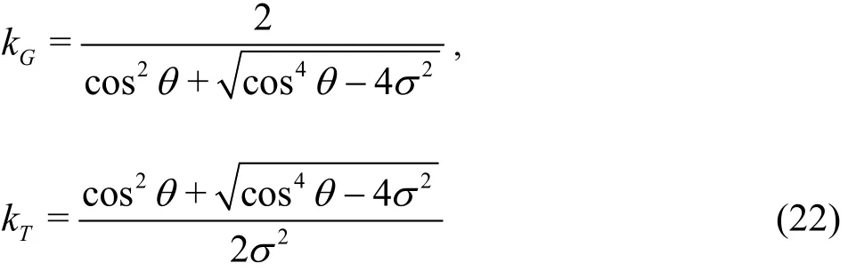
Then, we consider the capillary-gravity ship wave patterns for different translating velocities.Figure 3 depicts the free-surface profile generated by a travelling source with the same submergence as in Fig.2 on the upper part and far-field wave creastlines on the lower part at σ=0.06. In this scenario, the translating speed isU=0.67m/s which is larger than the critical speedcdiv=0.45m/s, and thus the gravity-dominant wave pattern is composed of three wave systems including transverse waves, divergent waves and fan waves as illustrated on the lower part of Fig.3. On the upper part where the wave profile is exhibited, however, the contour lines at large polar angles are not smooth. In this region, fan waves and capillarity-dominant waves extending to infinity are present. Therefore, the non-smooth contour lines are caused by the interference between different wave systems.
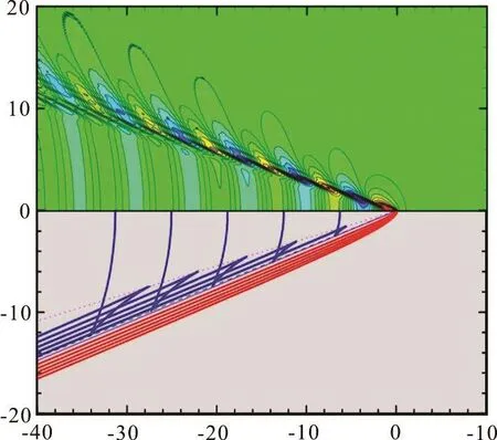
Fig.3 (Color online) Capillary-gravity ship wave pattern for σ=0.06 at which Fr =0.21 and U=0.67m/s>cdiv. Up pe r part: relief plot of the free -surface p rofile generated byatransla tingpo ints ourceloca tingat (x,y ,z)=(0,0,-0.2).Lowerpart:crestlinesobtainedfromthe asymptotic analysis
In Fig.4, the case at the translating speed equal to is considered. The numerically calculated wave pattern is presented on the upper part while the crestlines obtained from the asymptotic analysis are plotted on the lower part. From the asymptotic analysis conducted in Ref.[9], the divergent waves disappear just right while transverse waves and fan waves joint together as depicted on the lower part of the figure. On the upper part, divergent waves are also invisible, and the contours of the gravitydominant waves are smooth which is different from Fig.3. In addition, the capillarity-dominant waves with very short wavelength are observed.
Figure 5 displays the free-surface profile and the=0.45m/s corresponding far-field wave crestlines for =0.4σ at which the translating speed is 0.26 m/s less thanthis numerical example, the transverse waves and fan waves are merged to a new wave system referred to as transverse-fan waves, and this wave system is curved and extends smoothly outwards. The wave pattern generated by the translating source exhibited on the upper part is consistent with the crestlines plotted on the lower part with very obvious capillarity-dominant waves.
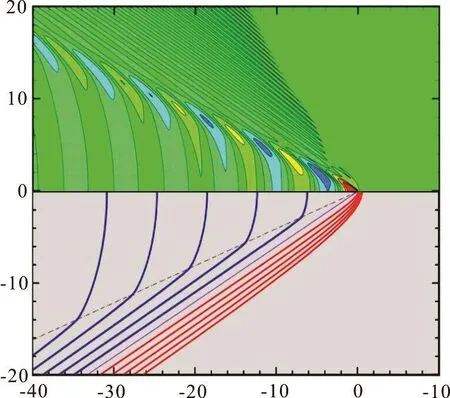
Fig.4 (Color online) Capillary-gravity ship wave pattern for=0.133 σ at which =0.14 Fr and div= =U c file generated by a translating point source locating at 0.45m/s . Upper part: relief plot of the free-surface pro-(,,)=(0,0,0.2)xyz -. Lower part: crestlines obtained from the asymptotic analysis
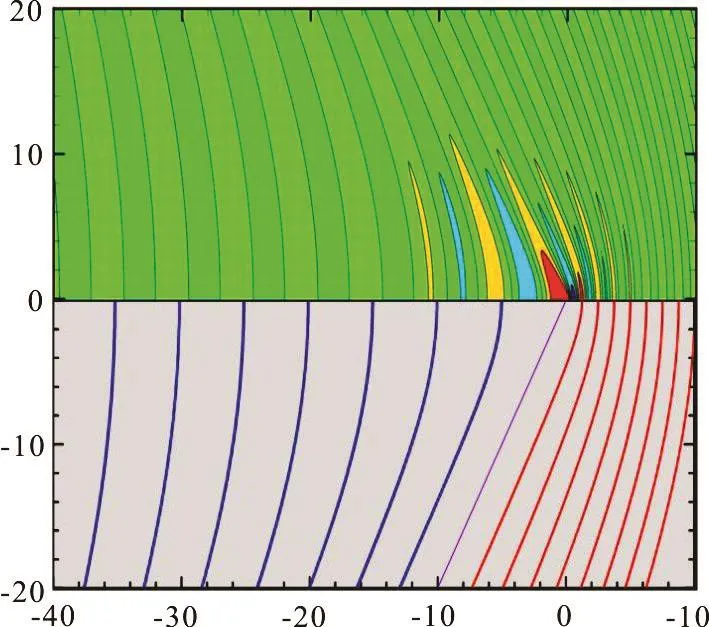
Fig.5 (Color online) Capillary-gravity ship wave pattern foratw hich =0.083 andU=0.26m/s<pper part: relief plot of the free-surfa ce profile ge- nerated bya transla ting point sourcelo cating at.Lower part:crestlinesobtained from the asymptotic analysis
4. Conclusion
In the present article, the capillary-gravity ship wave patterns generated by a steadily translating source are numerically studied for various travelling speeds across the critical speed cdiv=0.45m/s through formulating the free-surface Green function.Generally, the numerical calculation is consistent with the wave crestlines obtained from the asymptotic analysis. When the translating speed is greater than the critical speed cdiv=0.45m/s, fan waves are present and they pass through the region where transverse waves and divergent waves appear. So, the interference occurs between these wave systems resulting in non-smooth contours of the wave pattern.As the speed is less thancdiv=0.45m/s but larger thancmin=0.23m/s, the resultant transverse-fan wave pattern is curved and extends smoothly outwards.
Acknowledgements
The first author is indebted to Prof. Zhi Zong for his supervision on anearlywork of the subject when the first author was studying in Dalian University of Technology.
[1] Dias F. Ship waves and Kelvin [J]. Journal of Fluid Mechanics, 2014, 746: 1-4.
[2] Lighthill J. Waves in fluids [M]. Cambridge, UK: Cambridge University Press, 1960.
[3] Ellingsen S. A. Ship waves in the presence of uniform vorticity [J]. Journal of Fluid Mechanics, 2013, 742: R2.
[4] Zhu Y., He J., Zhang C. et al. Farfield waves created by a monohull ship in shallow water [J]. European Journal of Mechanics-B/Fluids, 2015, 49: 226-234.
[5] Pethiyagoda R., McCue S. W., Moroney T. J. et al.Jacobian-free Newton-Krylov methods with GPU acceleration for computing nonlinear ship wave patterns [J].Journal of Computational Physics, 2014, 269(10):297-313.
[6] Faltinsen O. M. Hydrodynamics of high-speed marine vehicles [M]. Cambridge, UK: Cambridge University Press, 2005.
[7] Doyle T. B., McKenzie J. F. Stationary wave patterns in deep water [J]. Quaestiones Mathematicae, 2013, 36(4):487-500.
[8] Moisy F., Rabaud M. Mach-like capillary-gravity wakes[J]. Physical Review E, 2014, 90(2): 023009.
[9] Liang H., Chen X. Far-field behaviours of steady capillary-gravity ship waves [C]. The 32nd International Workshop on Water Waves and Floating Bodies. Dalian,China, 2017.
[10] Lamb H. Hydrodynamics [M]. Sixth Edition. Cambridge,UK: Cambridge University Press, 1932.
[11] Binnie A. M. Solutions of the fish-line problem at intermediate velocities [J]. British Journal of Applied Physics,1965, 16(11): 1755-1758.
[12] Gradshtejn I. S., Ryzhik I. M. Table of integrals, series and products [M]. New York, USA: Academic Press, 1965.
[13] Crapper G. D. Surface waves generated by a travelling pressure point [J]. Proceedings of the Royal Society London, 1964, 282(1391): 547-558.
[14] Chen X. B., Noblesse F. Dispersion relation and far-field waves [C]. The 12th International WorkshoponWater Waves and Floating Bodies. Carry le Rouet, France, 1997.
[15] Chen X. B. Analytical features of unsteady ship waves(Chwang A. T., Teng M. H., Valentine D. T. Advances in Engineering Mechanic–Reflections and outlook [M].Singapore: World Scientific, 2004, 371-389.
[16] Dias F., Dyachenko A. I., Zakharov V. E. Theory of weakly damped free-surface flows: A new formulation based on potential flow solutions [J]. Physics Letters A, 2008,372(8): 1297-1302.
[17] Noblesse F., Chen X. B. Decomposition of free-surface effects into wave and near-field components [J]. Ship Technology Research, 1995, 42: 167-185.
[18] Noblesse F., He J., Zhu Y. Why can ship wakes appear narrower than Kelvin's angle?[J]. EuropeanJournal of Mechanics-B/Fluids, 2014, 46: 164-171.
* Biography: Hui Liang (1988-), Male, Ph. D.,Research Engineer
Xiaobo Chen,
E-mail: xiao-bo.chen@bureauveritas.com
杂志排行

水动力学研究与进展 B辑的其它文章
- On the clean numerical simulation (CNS) of chaotic dynamic systems *
- Flowstructure and phosphorus adsorption in bed sediment at a 90° channel conflunce
- Determination of urban runoff coefficient using time series inverse modeling *
- An ISPH model for flow-like landslides and interaction with structures *
- Stationary phase and practical numerical evaluation of ship waves in shallow water *
- Theoretical and numerical investigations of wave resonance between two floating bodies in close proximity *