Effects of rotational speeds on the performance of a centrifugal pump with a variable-pitch inducer *
2017-11-02XiaomeiGuo郭晓梅ZuchaoZhu朱祖超GaopingShi施高萍YongHuang黄勇
Xiao-mei Guo (郭晓梅), Zu-chao Zhu (朱祖超), Gao-ping Shi (施高萍), Yong Huang (黄勇)
1. School of Mechanical and Automotive Engineering, Zhejiang University of Water Resources and Electric Power, Hangzhou 310018, China, E-mail: guoxiaomei19@163.com
2. The Zhejiang Provincial Key Laboratory of Fluid Transmission Technology, Zhejiang Science and Technology University, Hangzhou 310018, China
(Received May 3, 2015, Revised February 3, 2016)
Effects of rotational speeds on the performance of a centrifugal pump with a variable-pitch inducer*
Xiao-mei Guo (郭晓梅)1, Zu-chao Zhu (朱祖超)2, Gao-ping Shi (施高萍)1, Yong Huang (黄勇)1
1. School of Mechanical and Automotive Engineering, Zhejiang University of Water Resources and Electric Power, Hangzhou 310018, China, E-mail: guoxiaomei19@163.com
2. The Zhejiang Provincial Key Laboratory of Fluid Transmission Technology, Zhejiang Science and Technology University, Hangzhou 310018, China
(Received May 3, 2015, Revised February 3, 2016)
The centrifugal pumps usually work at various rotational speeds. The variation in the rotational speeds will affect the internal flow, the external performance, and the anti-cavitation performance of the pump. In order to improve the anti-cavitation performance of the centrifugal pumps, variable-pitch inducers are placed upstream of the impeller. Because the rotational speeds directly affect the flow and the performance of the pump, it is essential to characterize the performance of the pump with a variable-pitch inducer at various rotational speeds. In this paper, the simulations and the experimental tests of a centrifugal pump with a variable-pitch inducer are designed and carried out under various rotational speed conditions. Navier-Stokes equations, coupled with a Reynolds average simulation approach, are used in the simulations. In the experimental tests, the external and anti-cavitation performances of the pump are investigated in a closed system. The following results are obtained from the simulations. Firstly, the velocity in the passage of the inducer rises with the increase of the rotational speed. Secondly, the static pressure escalates on the inducer and the impeller with the increase of the rotational speed. Thirdly, the static pressure distribution on the inducer and the impeller is asymmetric. Fourthly, the anti-cavitation performance of the pump deteriorates with the increase of the rotational speed. Additional results are gathered from an analysis of the experiments. H-Q curves are similar parabolas at various rotational speeds, while η-Q curves are similar parabolas only when n ≤ 6 000r/min . The anti-cavitation performance of the pump deteriorates with the increase of the rotational speed.Finally, the simulation results are found to be consistent with the experimental results.
Centrifugal pumps, external characteristics experiments, rotational speeds, anti-cavitation performance
Introduction
The centrifugal pumps have a wide range of applications in areas such as petroleum, chemical, and aerospace industries. In reality, the centrifugal pumps with a variable-pitch inducer usually work under various operational conditions, especially at various rotational speeds. In the case of high rotational speeds,the use of the impeller with a variable-pitch inducer upstream is an effective method to improve the weakened anti-cavitation performance of the pumps[1-3].Therefore, it is important to characterize the flow distribution and the performance of the pumps with a variable-pitch inducer at various rotational speeds.
This work differs from most existing studies in several aspects. It is proposed here that similarity transformation is performed at various rotational speeds. Factors resulting in a vortex on the axial section of the inducer are analyzed. The cavitations at various rotational speeds are discussed, and the relationship between the anti-cavitation performance and the rotational speeds is determined.
1. Literature review
Extensive studies were devoted to improve the pump performance under various operational conditions, but not many at various rotational speeds,especially for a pump with a variable-pitch inducer.For example, the optimal design of the pumps wasdiscussed in studies[4,5]where the hydraulic performance of the pumps under different operational conditions was investigated using numerical and experimental methods. The transient performance of the pumps during startup or shutdown was discussed[6-10].The anti-cavitation performance of the pumps under different operational conditions and inlet pressures was also researched[11,12].
Some studies discussed the effect of the rotational speeds on the pump performance, but without due considerations of the inducer. For example, Wu et al.[13]studied the effect of the rotational speed on the pump performance. They proposed that the rotational speed is the main parameter in the design and the use of a full metal screw pump. Zhu et al.[14]conducted experiments for external characteristics and performed numerical calculations for the internal flow of a centrifugal pump with an open impeller during startup.They concluded that the rotational speed significantly affects the internal flow.
In summary, the existing studies indicate that it is important to characterize the performance of a centrifugal pump with a variable-pitch inducer at different rotational speeds. Based on previous studies[1,2], this paper is to reveal the effect of the rotational speed on the performance of a centrifugal pump with a variable-pitch inducer.
2. Numerical calculation model
Theanti-cavitation performance at various rotational speeds is investigated for a high-speed centrifugal pump with a variable-pitch inducer. The high-speed centrifugal pump, the variable-pitch inducer, and the impeller are shown in Fig.1, respectively.The pump design parameters include the flow rateQ=4m3/h , the headH=100m, and the rotational speedn=6000r/min. Moreover, the main dimensions are given in Table 1.
The calculation area in Fig.2 includes the inlet pipe, the inducer, the impeller, and the volute. For the numerical simulation, the inducer and the impeller are approximated as a whole part, denoted as ind-imp.Thus, the whole calculation model is composed of three parts with two interfaces. The first interface is between the inlet pipe and the ind-imp, and the second interface is between the ind-imp and the volute. The mesh grids are generated using the GAMBIT software.The unstructured grids are used for the ind-imp part because of its complex three-dimensional geometry.The range of the distributions ofyplus is from 25 to 102. The independence of the mesh grid is analyzed with the results given in Table 2. The table shows that in the case of a mesh interval size less than 0.5 mm,the head value is relatively stable. Thus, the mesh interval size for the numerical model is chosen as 0.5 mm.The total grid number of the calculation area is 828 128. The quality of the meshes is checked by using the Equi-Angle skew and the Equi-Size skew of meshes, andboth are less than0.83, which satisfiesthree-dimensional turbulent flow at various rotational speeds is simulated using the ANSYS-CFX software to observe the flow behavior of the inducer. A normal speed boundary condition vin= Q / A = Q /(1/4πis specified at the inlet, and a static pressure boundary condition is specified at the outlet. The results are obtained through external characteristics experiments.In the simulation, a single-phase flow is assumed and the water of ρ = 1.0× 1 03kg/m3at temperature of 25oC is used.

Fig.1 Centrifugal pump with a variable-pitch inducer

Table 1 Main dimensions of the high-speed centrifugal pump

Fig.2 (Color online) Calculation areas

Table 2 Mesh grid independence test
Many studies pointed out that a Re-Normalization Group (RNG) -k model is usually adopted in the simulation of a rotational machine, such as the pump, the inducer, and the turbo[1,17-20]. The simulation is carried out by solving the Navier-Stokes equations, coupled with a Reynolds average simulation approach. The conservation equation is[14]

where1FandvFare the non-viscous flux and the viscous flux, respectively. Uis used for solving the conservation of the variable. Lastly, is used as a source item.
The turbulent model is a -k model, which is


The rotational speeds in this paper are set in a range from 3 000 r/min to 8 000 r/min. Firstly,similarity operational conditions at various rotational speedsshould be set.The conversion formulas of thehead and the flow rate

wheredesH ,desQ anddesn represent the head, the flow rate, and the rotational speed under the design conditions, respectively. The results of convertionsunder the similarity operational conditions at various rotational speeds by using Eq.(3) are shown in Fig.3.
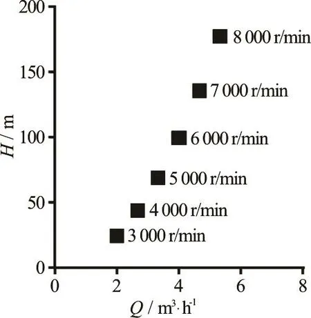
Fig.3 Similarity operational conditions at various rotational speeds

Fig.4 (Color online) Axial sections profiled in the passage of the inducer
3. Numerical calculation results and analysis
The inner flow and pressure distributions are obtained by simulations. In Fig.4, Edge A is far from the volute tongue, while Edge B is near the volute tongue. The two vertical sections are named ISO surface I and ISO surface II.
The two ISO axial sections in the passage of the variable-pitch inducer are considered to show the flow streamlines (Fig.5).
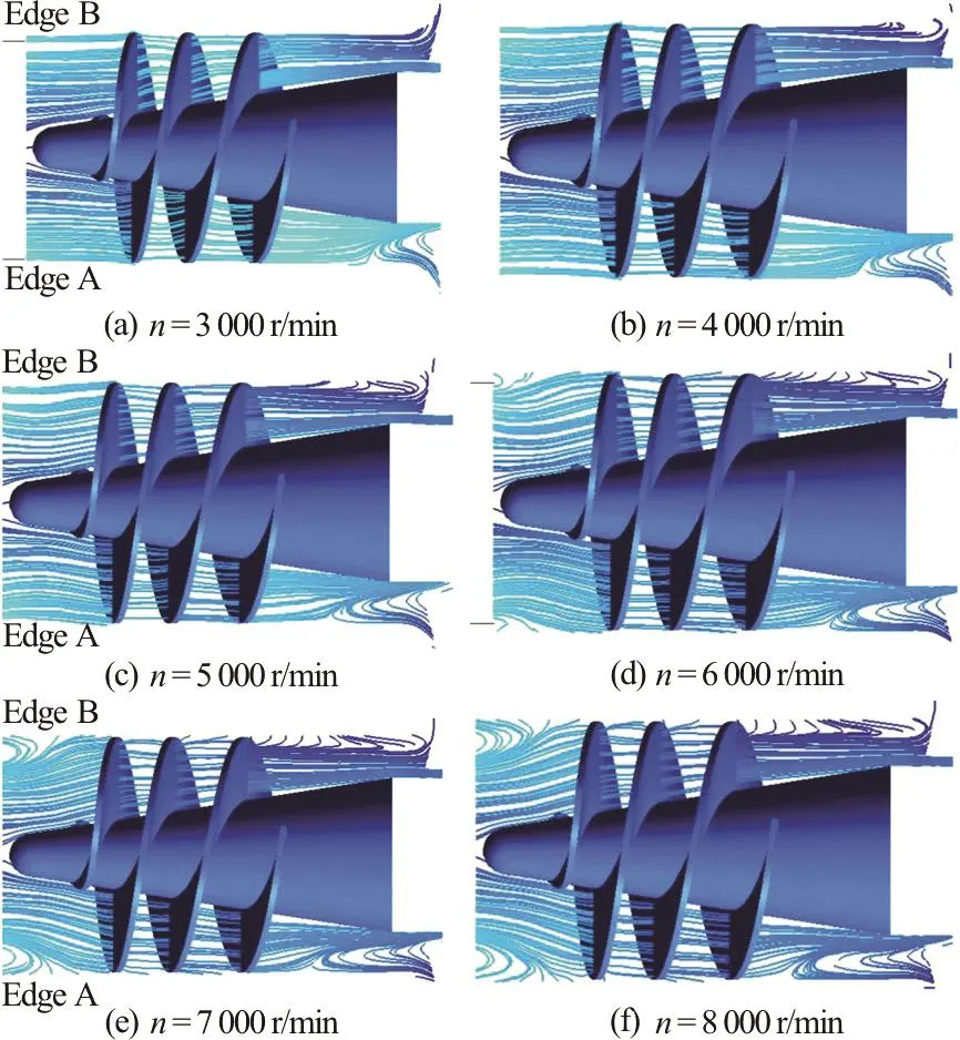
Fig.5 (Color online) Streamline distributions on ISO surface I
Figure 5 shows the streamline distributions on ISO surface I when the inducer rotates from Edge B to Edge A in the clockwise direction. Figure 5(a) shows the case whenn=3000r/min . No vortex occurs at the inlet of the inducer near Edge A or Edge B, while a vortex does appear at the outlet of the inducer near Edge A.Figure5(b)showsthe case whenn=4000r/min. Again, there is no vortex at the inlet,but a vortex does appear at the outlet near Edge A and is larger than that in Fig.5(a). Figures 5(a) and 5(b)show that the vortex mainly appears at the outlet near Edge A.Figure5(c)showsthecasewhenn=5000r/min and there is no vortex at the inlet,although the streamlines are not as straight. The vortex at the outlet near Edge A is larger than that in Figs.5(a) and 5(b), and a vortex at Edge B is now visible. Figure 5(d) shows the case whenn=6000r/min, and vortices begin to appear at the inlet near both Edge A and Edge B. The vortices at the outlet near Edge A and Edge B continue to expand. In Figs.5(e) and 5(f), the cases whenn=7 000 r/min and 8 000 r/min are shown. It is observed that the vortices located at the inlet and the outlet near both Edge A and Edge B expand gradually. Thus, one can conclude that as the rotational speed increases, the velocity in the passage also increases with an increase in the intensity of the vortices. However, the vortex will become less intense when the inducer rotates from Edge A to Edge B.
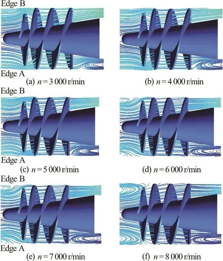
Fig.6 (Color online) Streamline distributions on ISO surface II
In order to analyze the results further, another ISO surface (ISO surface II) is analyzed. Figure 6 shows the streamline distribution on ISO surface II. In comparison, the streamline at the inlet on ISO surface II is less straight, while the streamline at the outlet near Edge B on ISO surface II is straighter in Figs.6(a)through 6(c) than in Figs.5(a) through 5(c) (cases when n ranges between 3 000 r/min and 5 000 r/min).A comparison between Figs.6(d) through 6(f) and Figs.5(d) through 5(f) (cases whennranges between 6 000 r/min and 8 000 r/min) shows that a vortex exists at the outlet near Edge A on ISO surface II, and this vortex is larger than that on ISO surface I. The vortex at the inlet on ISO surface II begins to appear whenn=3000r/min , and evolves quickly. Combining the results shown in Figs.4, 5 and 6, one can conclude that the increased rotational speed of the inducer causes the vortex in the inducer to grow. The explanation may be that the vortex intensionΓis mainly related with the angular speed ,Γ=A more intense vortex is observed further away from the volute tongue.
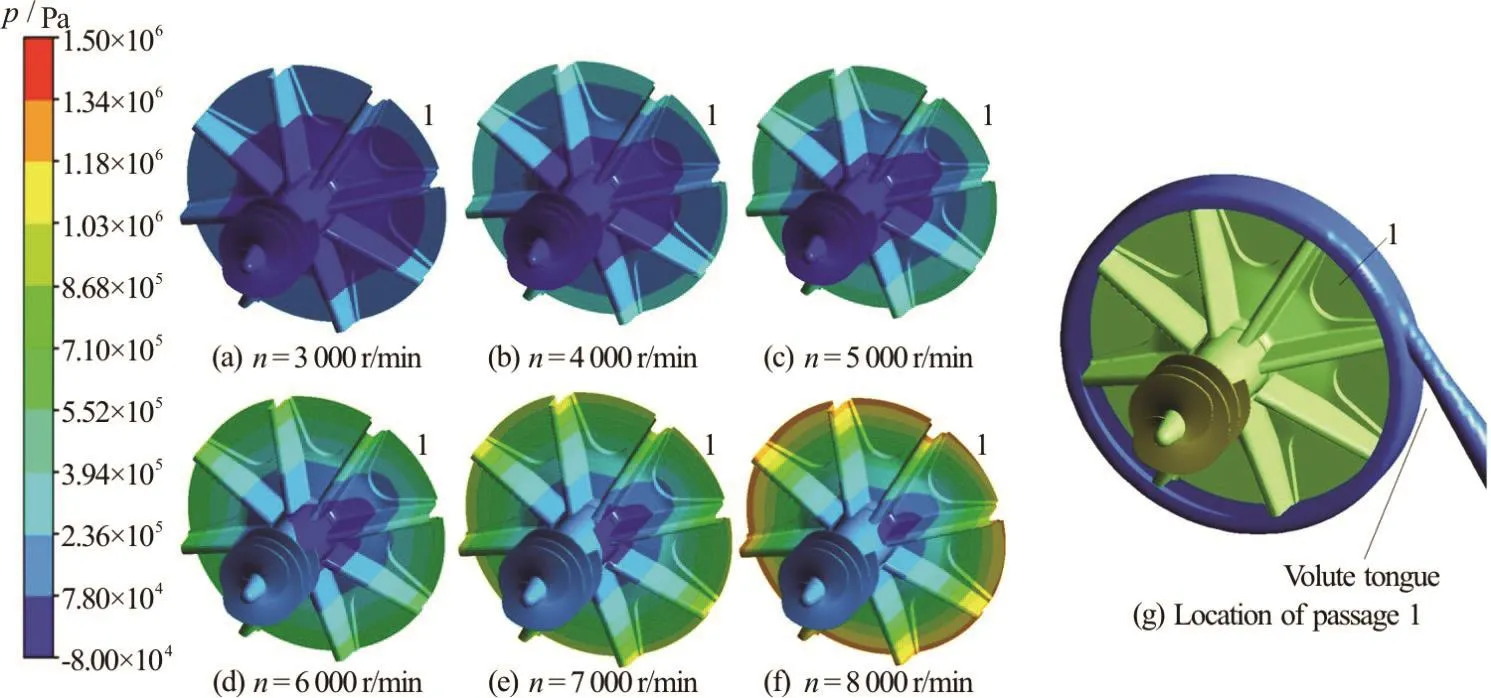
Fig.7 (Color online) Static pressure ()pdistributions on the inducer and the impeller
Figure 7 shows the static pressure distributions on the inducer and the impeller. From Figs.7(a)through 7(f), it is clear that the static pressure increases on bot h the induc er and the im pelle r with the increaseoftherotationalspeed.Thestaticpressure gradually rises from the inlet of the inducer to the outlet of the impeller, what has been simulated in the paper[21,22]. An asymmetric distribution of the static pressure on the inducer and the impeller is also observed. When the passage rotates to the passage 1 (as seen in Fig.7(g)), the static pressure is decreased to a point below the saturation pressure, and the cavitation takes place. With the rotation, the passage will rotate to the next passage, the static pressure will increase,and the vapor volume fraction will decrease. Thus, we will have an asymmetric distribution of the static pressure and the cavitation on the inducer and the impeller. Furthermore, the lowest static pressure (denoted byLpin Fig.7) is on the suction surface of the impeller's blade in passage 1. The location of Passage 1 is shown in Fig.7(g), and the normalized values ofpLat various rotational speeds are shown in Fig.8.

Fig.8 Lowest static pressure Lp on the impeller
Figure 8 shows thatpLdecreases with the increase of the rotational speed under similarity operational conditions. Therefore, the anti-cavitation performance of the pump deteriorates with the incr ease of the rotation al speed. Fig ure 8 also shows thattheanti-cavitationperformanceofacentrifugal pump with an inducer is better than that without an inducer. Whennreaches 5 000 r/min,Lpis almost equal to the saturation pressuresp. With a further increase ofn,Lpbecomes less thansp, which means that the cavitation occurs. After setting the impeller with the variable-pitch inducer upstream, the anti-cavitation performance is clearly improved.Lpis less thansponly whennreaches 7 000 r/min.Thus, under a designated rotational speed, theLpof a pump without an inducer is lower than that with a variable-pitch inducer.
Figure 9 shows the lowest static pressure on the impeller and the inducer in thecase whenn=6000r/min . Figure 9 also shows that the static pressure on the pressure surface of the blades is higher than that on the suction surface at the same radial location. Also, a lower static pressure occurs at the inlet of the suction surfaces (Fig.9 Area 1 and Area 2).A low static pressure is also observed at the outlet of the inducer (Fig.9 Area 3).
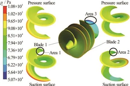
Fig.9 (Color online) Static pressure distributions on the inducer when =n 6000r/min
4. Experiments for external characteristics
Experimental tests are carried out in the designed experimental setup, as shown in Fig.10. The setup mainly includes a water tank, a centrifugal pump unit,pipelines, a vacuum pump, and measurement devices.In these tests, a frequency motor is used to drive the pump. The specified output power is 22 KW, the specified frequency is 100 Hz, the specified voltage is 380 V, and the torque is 35 Nm.
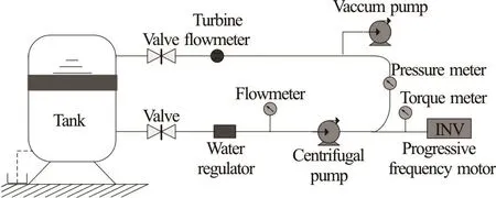
Fig.10 Experimental setup
The external performance and the anti-cavitation performance of the pump are evaluated by the experimental tests. The results are illustrated in Figs.11 and 12.
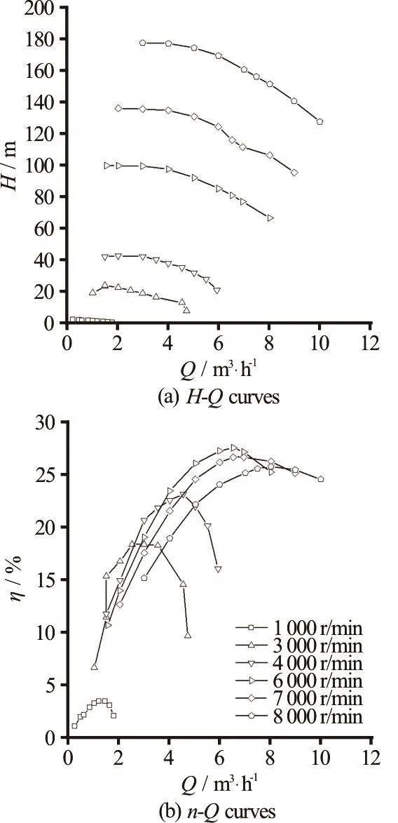
Fig.11 Head versus flow rate curves and efficiency versus flow rate curves
In Fig.11, there are two types of curves. One is the -HQcurve, and the other is the -Qηcurve.The -HQcurves show a monotonic decrease at one rotational speed, in similar parabolas at various rotational speeds. At each rotational speed, the lower the flow rate, the higher the head. Theη-Qcurves arealsosimilar parabolasfor caseswhenn≤6000r/min . However, theη-Qcurves are not similar parabolas whennis in the range between 7 000 r/min and 8 000 r/min. The rotational speed, the Reynolds number, and the shaft power are all factors that contribute to this phenomenon. The cavitation usually occurs at high rotational speeds,as demonstrated earlier by the simulations (Fig.8). When the rotational speed reaches even higher values, the cavitation becomes more severe. A high flow velocity causes the Reynolds number to change at high rotational speeds. Whennis higher than 7 000 r/min,the shaft power is related to the rotational speed to the third power rather than the square power. These three main factors affect the external performance of the pump at a high rotational speed.
The data from the cavitation experiments are summarized in Fig.12. During the experiments, it is difficult to measure the low rotational speeds (nin the range between 3 000 r/min and 5 000 r/min). Thus,the critical point of the drop ofHis not clear whennis between 3 000 r/min and 5 000 r/min, especially forQ=1.5m3/h (Figs.12(a) through 12(b)). In order to analyze the experimental data more accurately, the data shown in Figs.12(c) through 12(f) are analyzed.The critical pressure (defined as the one whenHdrops suddenly) rises with the increase of the flow flux at the same rotational speed, as shown in Figs.12(c) through 12(f). Therefore, the anti-cavitation performance is better at a low flow flux at the same rotational speed. It is clear from Figs.12(c) through 12(f) that the critical pressure rises with the increase of the rotational speed. This means that the anti-cavitation performance deteriorates with the increase of the rotational speed. These results are consistent with theanalysis results of earlier simulations (Fig.7).
In order to analyze the performance at various rotational speeds more accurately, experiments under similar operational conditions (Fig.3) are conducted.The results of the experiments are shown in Fig.13 and Fig.14. Whennis between 3 000 r/min and 4 000 r/min,H, andNPSHr(Net positive suction head must) is not appropriate for indicating the variation of the inlet pressure.
Figure 13 showsη-Qcurves under similar operational conditions. In Fig.13, the trends of theη-Qobtained by the simulation and the experiment are consistent. Curves experiment without an inducer and experiment with an inducer show that the efficiency ofth e pumpwi th an in ducerarea li ttle higherthanthatwithoutaninducer,andtheeffectof the inducer on the pump efficiency is small. From Fig.13, it can be seen that the efficiency performance of the pump gets higher with the increase of the rotational speeds. This result is in conformity with the theory.

Fig.12 Head versus inlet0/pp (where inletp is the inlet static pressure) curves
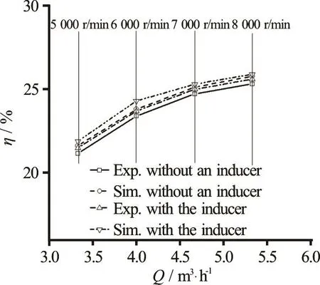
Fig.13 -Qηcurves under similar operation conditions
Figure 14 showsNPSHr-Qcurves under similar operational conditions. In Fig.14, the trends of theNPSHrobtained by the simulation and the experiment are consistent. Curves simulation without an inducer and experiment without an inducer show that the anti-cavitation performance of the pump without an inducer is poor when theNPSHris above 1.86 m. Curves simulation with the inducer and experiment with the inducer show that the anti-cavitation performance of the pump is improved with an inducer.Furthermore, in Fig.14, we observe thatNPSHrincreases with the increase of the rotational speed.Therefore, the anti-cavitation performance of the pump deteriorates with the increase of the rotational speeds. This can be explained by the variations ofNPSHr(Eq.(4)).
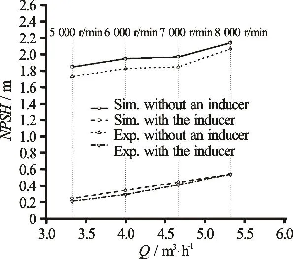
Fig.14 NPSHr -Q curves under similar operation conditions

Under similar operational conditions, the abso-lute velocity v0and the relative velocity ω0before the blade of the impeller are increased with the increase of the rotational speed. Thus, according to the equation, the higher the values v0and ω0, the higher the N P SHr. These results are consistent with the conclusions drawn from the simulations (Fig.8).
5. Conclusions
The performance of a centrifugal pump with a variable-pitch inducer at various rotational speeds is investigated numerically and experimentally. The results of the numerical simulations are consistent with those of the experiments.
The simulations under six similar operational conditions are compared. It is evident from the streamline distribution analysis that the velocity in the passage increases with the increase of the rotational speed. Furthermore, an increase in the velocity will intensify the vortices. The vortices in the inducer are intensified with the rotation of the inducer. The vortices become more intense as one goes far away from the volute tongue.
It is observed that the static pressure is increased on both the inducer and the impeller with the increase of the rotational speed, as demonstrated by the analysis of the static pressure distributions on the impeller and the inducer. The static pressure is gradually increased from the inlet of the inducer to the outlet of the impeller. Furthermore, one observes the asymmetric distribution of the static pressure on the inducer and the impeller. The lowest static pressure on the impeller under similar operational conditions is decreased with the increase of the rotational speed.Therefore, the anti-cavitation performance of the pump is deteriorated with the increase of the rotational speed.
In addition, experiments under six similar operational conditions are conducted. It is shown that the -H Q curves maintain the shape of similar parabolas at various rotational speeds. However, the η- Q curves are similar parabolas when n ≤ 6 000r/min, and non-similar parabolas in cases when n > 6 000r/min . The experiments also show that N P SHris increased with the increase of the rotational speed, which means that the anti-cavitation performance of the pump is deteriorated with the increase of the rotational speed.
[1] Guo X. M., Zhu L. H., Zhu Z. C. et al. Numerical and experimental investigations on the cavitation characteristics of a high-speed centrifugal pump with a splitterblade inducer [J]. Journal of Mechanical Science and Technology, 2015, 29(1): 259-267.
[2] Guo X. M., Zhu L. H., Zhu Z. C. et al. The rotating cavitation performance of a centrifugal pump with a splitterbladed inducer under different rotational speed [J]. International Journal of Turboand Jet Engineering, 2015,32(3): 275-283.
[3] Zhu Z. C., Xie P., Ou G. F. et al.. Design and experimental analyses of small-flow high-head centrifugal-vortex pump for gas-liquid two-phase mixture [J]. Chinese Journal of Chemical Engineering, 2008, 16(4): 528-534.
[4] Mahar P., Singh R. Optimal design of pumping mains considering pump characteristics [J]. Journal of Pipeline Systems Engineering and Practice, 2014, 5(1): 04013010.
[5] Kilic E., Dolen M., Caliskan H. et al. Pressure prediction on a variable-speed pump controlled hydraulic system using structured recurrent neural networks [J]. Control Engineering Practice, 2014, 26(1): 51-71.
[6] Zhang Y. L., Li Y., Zhu Z. C. et al. Computational analysis of centrifugal pump delivering solid-liquid twophase flow during startup period [J]. Chinese Journal of Mechanical Engineering, 2014, 27(1): 178-185.
[7] Li Z., Wu D., Wang L. et al. Numerical simulation of the transient flow in a centrifugal pump during starting period[J]. Journal of Fluids Engineering, 2010, 132(8): 081102.
[8] Chen T. J., Luo X. Q., Guo P. C. et al. 3-D Simulation of a prototype pump-turbine during starting period in turbine model [C]. 6th International Conference on Pumps and Fans withCompressors and Wind Turbines. Beijing,China, 2013.
[9] Zhang Y. L., Zhu Z. C., Jin Y. Z. et al. Experimental study on a centrifugal pump with an open impeller during startup period [J]. Journal of Thermal Science, 2013, 22(1):1-6.
[10] Farhadi K, Bousbia-salah A., D'auria F. A model for the analysis of pump start-up transients in Tehran research reactor [J]. Progress inNuclear Energy, 2007, 49(7):499-510.
[11] Zhang R., Chen H. X. Numerical analysis of cavitation within slanted axial-flow pump [J]. Journal of Hydrodynamics, 2013, 25(5): 663-672.
[12] Ahonen T., Tamminen J., Ahola J. et al. Novel method for detecting cavitation in centrifugal pump with fre- quency converter [J]. Insight, 2011, 53(8): 439-445.
[13] Wu J. F., Lan J. B., Meng F. G. et al. Simulation study for the effects of rotational speed on performance of full metal single screw pump [C]. Advanced Polymer Processing International Forum. Qingdao, China, 2013.
[14] Zhu Z. C., Guo X. M., Cui B. L. et al. External characteristics and internal flow features of a centrifugal pump during rapid startup [J]. Chinese Journal of Mechanical Engineering, 2011, 24(5): 798-804.
[15] Ji B., Luo X. W., Arndt R. E. A. et al. Numerical simulation of three dimensional cavitation shedding dynamics with special emphasis on cavitation–vortex interaction [J].Ocean Engineering, 2014, 87: 64-77.
[16] Ji B., Luo X. W., Wu Y. L. Unsteady cavitation characteristics and alleviation of pressure fluctuations around marine propellers with different skew angles [J]. Journal of Mechanical Science and Technology, 2014, 28(4):1339-1348.
[17] Byskov R. K., Jacobsen C. B., Pedersen N. Flow in a centrifugal pumpimpeller at design and off-design conditions-Part ii: Large eddy simulations [J]. Journal of Fluids Engineering, 2003, 125(1): 73-83.
[18] Cui B. L., Lin Y. G., Jin Y. Z. Numerical simulation of flow in centrifugal pump with complex impeller [J]. Journal of Thermal Science, 2011, 20(1): 47-52.
[19] Luo X. W., Ji B., Tsujimoto Y. A review of cavitation in hydraulic machinery [J]. Journal of Hydrodynamics, 2016,28(3): 335-358.
[20] Fiaschi D., Graniglia R., Manfrida G. Improving the effectiveness of solar pumping systems by using modular centrifugal pumps with variable rotational speed [J]. Solar Energy, 2005, 79(3): 234-244.
[21] Guo X. M., Zhu Z. C., Cui B. L. et al. Effects of the number of inducer blades on the anti-cavitation characteristics and external performance of a centrifugal pump [J].Journal of Mechanical Science and Technology, 2016,30(7): 3173-3181.
[22] Guo X. M., Zhu Z. C., Cui B. L. Effects of the short blade locations on the anti-cavitation performance of the splitter-bladed inducer and the pump [J]. Chinese Journal of Chemical Engineering, 2015, 23(7): 1095-1101.
* Project supported by the National Natural Science Foundation of China (Grant Nos. 51406185, 51579225), the Third Level 151 Talent Project in Zhejiang Province.
Biography: Xiao-mei Guo (1979-), Female, Ph. D., Professor
Zu-chao Zhu,
E-mail: zuczhu@163.com
猜你喜欢
杂志排行
水动力学研究与进展 B辑的其它文章
- On the clean numerical simulation (CNS) of chaotic dynamic systems *
- Flowstructure and phosphorus adsorption in bed sediment at a 90° channel conflunce
- Determination of urban runoff coefficient using time series inverse modeling *
- An ISPH model for flow-like landslides and interaction with structures *
- Capillary-gravity ship wave patterns *
- Stationary phase and practical numerical evaluation of ship waves in shallow water *
