Simulation of flows with moving contact lines on a dual-resolution Cartesian grid using a diffuse-interface immersed-boundary method *
2017-11-02HaoranLiu刘浩然HanLi李晗HangDing丁航
Hao-ran Liu (刘浩然), Han Li (李晗), Hang Ding (丁航)
Department of Modern Mechanics, University of Science and Technology of China, Hefei 230027, China,
E-mail: liuhr@ustc.edu.cn
(Received July 29, 2017, Revised August 3, 2017)
Simulation of flows with moving contact lines on a dual-resolution Cartesian grid using a diffuse-interface immersed-boundary method*
Hao-ran Liu (刘浩然), Han Li (李晗), Hang Ding (丁航)
Department of Modern Mechanics, University of Science and Technology of China, Hefei 230027, China,
E-mail: liuhr@ustc.edu.cn
(Received July 29, 2017, Revised August 3, 2017)
In this paper, we investigate flows with moving contact lines on curved solid walls on a dual-resolution grid using a diffuse-interface immersed-boundary (DIIB) method. The dual-resolution grid, on which the flows are solved on a coarse mesh while the interface is resolved on a fine mesh, was shown to significantly improve the computational efficiency when simulating multiphase flows. On the other hand, the DIIB method is able to resolve dynamic wetting on curved substrates on a Cartesian grid, but it usually requires a mesh of high resolution in the vicinity of a moving contact line to resolve the local flow. In the present study, we couple the DIIB method with the dual-resolution grid, to improve the interface resolution for flows with moving contact lines on curved solid walls at an affordable cost. The dynamic behavior of moving contact lines is validated by studying drop spreading, and the numerical results suggest that the effective slip lengthnλ can be approximated by 1.9Cn, where Cn is a dimensionless measure of the thickness of the diffuse interface. We also apply the method to drop impact onto a convex substrate, and the results on the dual-resolution grid are in good agreement with those on a single-resolution grid. It shows that the axisymmetric simulations using the DIIB method on the dual-resolution grid saves nearly 60% of the computational time compared with that on a single-resolution grid.
Dual-resolution grid, moving contact lines, diffuse interface model, multiphase flows
Introduction
Diffuse interface method is one of the most popular approaches that are used to track the time evolution of fluid-fluid interfaces in simulation of multiphase flows[1,2]. In this method, the fluid-fluid interface, which is assumed to be mathematically sharp, is modeled by a diffuse interface of finite thickness. Although the diffuse interface method is simple in implementation and accurate in computing surface tension force, the numerical results with respect to interface resolution are not as good as other interface capturing methods such as level set and volume of fluid. In order to improve the interface resolution, Ding and Yuan[3]proposed to use a dual-resolution grid, on which the order parameter is discretized on a fine grid while the flow parameters such as pressure and velocity are discretized on a coarse mesh. The coupling between the fine and coarse grids is carefully designed such that it can guarantee that the volume of fluids and the computation of surface tension force are conserved.Moreover, it has been shown that the dual-resolution grid could save nearly 70% of the computational time in two-dimensional simulations and 80%in threedimensional simulations, and produced nearly the same results as the single-resolution grid[3].
There is few literature so far for the simulation of flows with moving contact lines on a dual-resolution grid. As far as we know, the only one available is the work by Patil et al.[4], in which a similar dualresolution grid algorithm is implemented with level set method to study the impact of a droplet on hydrophobic surface. However, the dynamic behavior of moving contact line on a dual-resolution grid was not addressed[3,4], especially the effective slip length on a dual-resolution grid and its difference from the single-grid method.
A diffuse-interface immersed-boundary (DIIB)method was recently developed to simulate flows with moving contact lines on a curved solid wall[5]. This method consists of a three-component diffuse interface model, an immersed boundary method and a characteristic moving contact line model. When being implemented on a Cartesian grid, it has been shown to be able to accurately simulate the cavity formation during the water entry of solid objects[6]and the spreading and retraction after drop impact onto a sphere[7]. Later, it was extended to investigate fluidstructure interaction involving dynamic wetting[8].Despite of its success, DIIB method is computationally expensive on a single-resolution Cartesian grid, in order to resolve the local flow in the vicinity of moving contact lines. In this regard, the dualresolution Cartesian grid is a viable alternative to the single-resolution one.
In this paper, we implement the DIIB method on a dual-resolution Cartesian grid, to investigate the flows with moving contact lines on curved substrates and examine the performance of the dual-resolution grid in simulating dynamics of moving contact lines.In particular, we validate the method by studying the drop spreading on a flat surface, and obtain the effective slip length by comparing with theoretical prediction. Then, we apply the method to drop impact onto a convex substrate, and the results on the dualresolution grid are compared against those on a single-resolution grid. Finally, we will check the improvement in computational efficiency between the dual-resolution grid and the single-resolution grid.
1. Methodology
1.1 Governing equations
The governing equations for the fluid flows are the dimensionless Navier-Stokes equations:


wheresf is the surface tension force andIBf represents the additional force to present the effects of solid substrates. The density and viscosity is defined as where CSand CLare the volume fraction of the solid and liquid phases respectively.CG=1- CL- CSis the volume fraction of the gas phase, and the density and viscosity ratio of the gas to theliquid are defined as ξρ= ρG/ρLand ξμ=μG/μL.Thegroupof dimensionless numbers includes Reynolds number Re= ρLU L/μL, Weber number We= ρLU2L/σ,where is surface tension coefficient. We shall also refer to the Ohnesorge number O h = W e0.5/Re.
1.2 Dual-resolution Cartesian grid
A dual-resolution Cartesian grid[3]contains two sets of Cartesian grids, each of which covers the whole domain but has different grid size h (see Fig.1), the fine grid has the half grid size of the coarse one. The variables are defined in a staggered manner on both grids, and specifically, the scalars are defined at the cell center and the vector components such as velocity are defined at the cell faces.
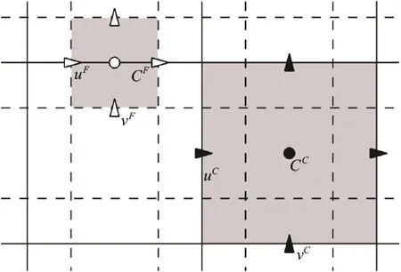
Fig.1 Configu ratio n of the d ual- reso lutio n Car tes ian grid. The dashed ands olidlinesare theg ridlines of the fine and coarsegrids,respectively.Thesymbolsinthecellwith shadow are samples for a sta ggered grid , the empty ones for the finegrid a nd f ullforco arse .Thes uper scrip ts C and F denotesthevariablesoncoarseandfinegrids, respectively
It is noteworthy that only the order parameter,here the volume fraction of one of the fluids C, is solved on the fine grid, and the flow variables such as pressure and velocity are solved on the coarse grid.However, we need the flow velocity on the fine grid to advect the interface; similarly, the distribution of C is also required on the coarse grid to identify the position of the interface, and then to compute the viscosity, density and surface tension force. The coupling of variables between the fine and coarse grids is performed by interpolation. The details of interpolation are illustrated in Fig.2, in which the variables on the fine and coarse grids are denoted by the superscriptsF and C, respectively. For example, the volume fraction on the coarse grid,CC ,can be integrated from that on the fine grid,FC , as follows

where the subscripts i and j represent the horizontal and vertical position of C, respectively. For the vertical component of the velocity, v, its value on the fine grid can be calculated by the interpolation scheme below:
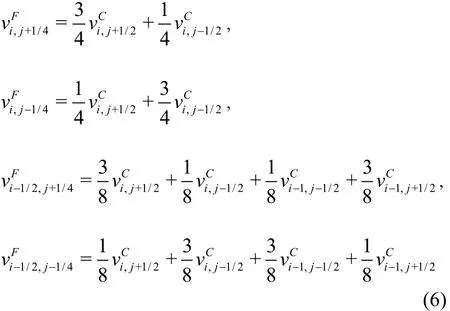
Similarly, the horizontal componentFu can be calculated fromCu.
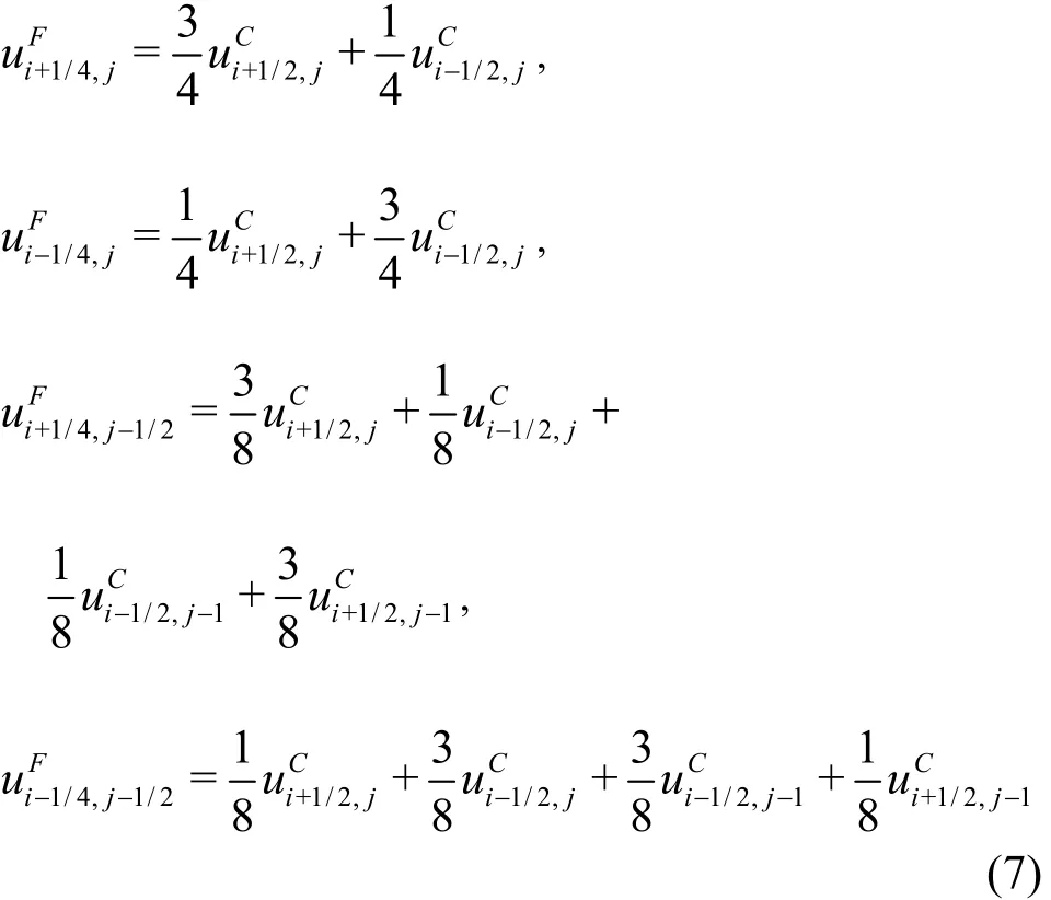
In the case of axisymmetric simulations, we can simply replace u and v in (6) and (7) by ru and rv, respectively, where r is the radial position of the velocity components.
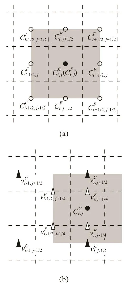
Fig.2 Relationship of volume fraction C (circles) and vertical component of velocity v (triangles) on the fine and coa- rse grids. The dashed lines are the grid lines on a fine grid (empty symbols), and the shadow is the cell of (,)ij on a coarse grid (filled symbols)
As shown in Ref.[3], this coupling between the two grids can ensure that the interpolated velocity is divergence-free at a discrete level and that the volume of each fluid and the computation surface tension force are conserved.
1.3 D

where the chemical potential is defined as

Note thatSC is determined by the position and shape of the solid object, andSC corresponds to the boundary of the solid object[5]. Cahn number Cn represents a dimensionless measure of the thickness of the diffuse interface, and Peclet number Pe denote the relative significance between the advection and the diffusion in the Cahn-Hilliard equation. In the present study, they are set to C n = 0.75h and P e = 1/Cn.
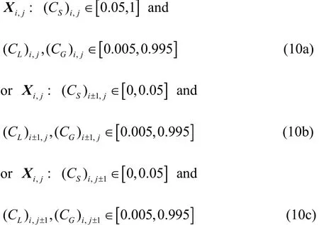
To account for the dynamic wetting on a curved substrate, a characteristic MCL model[5]is implemented in the ghost contact-line region, which includes the grid points,ijX that satisfy the following condition:
We compute the surface tension forcesf in a potential manner
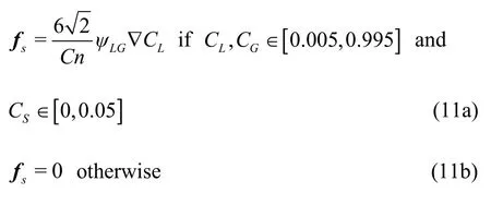
where the chemical potentialLGψ for the liquid-gas flow is defined as

An immersed boundary method is used to enforce the no-slip boundary condition at the curved solid substrates. In this method, a set of Lagrangian points for the curved solid substrates and the Cartesian Eulerian grids for the flows, as shown in Fig.3, and both the Lagrangian and Euler points are defined on a coarse grid.IBf in Eq.(1) is computed to correct the velocity*u on the Cartesian mesh, in such as way that the non-slip condition is effectively enforced at the Lagrangian points, where u*is the intermediate velocity calculated in the absence of fIB. This is conducted by computing uEaccording to the feedback acceleration aL

where Δt is the time step and Δs =2.4h is the arc length of the Lagrangian segments.D is the weighting function depending on the relative location between the Lagrangian and Eulerian points

where ()rδ is a Dirac delta function.
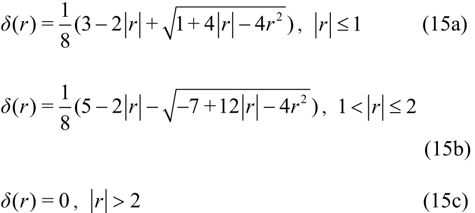


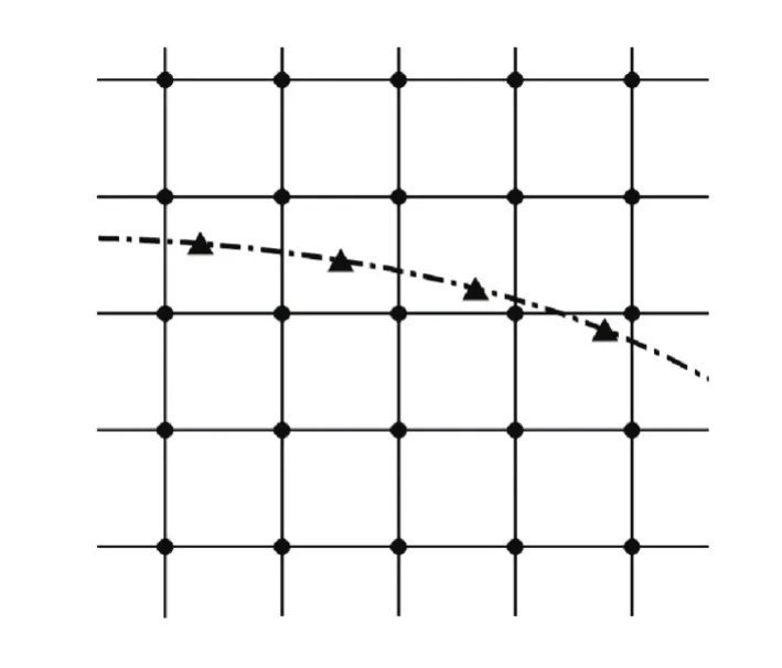
Fig. 3 Config uration o f th e grids used in IB me thod. The tri- anglesrepresenttheLagrangianpointsandthe circles for Euler points. The dash-dotted line denotes the curved sub- strate
wherelandmare the total numbers of the Lagrangian and Eulerian points.
1.4Discretization and solution procedure
Temporal discretization is performed in a temporally staggered manner, i.e., the velocity and pressure are defined attn,n= 1,2,3,…, while the volume fractionCLis defined at the time levelstn-1/2. For the convection and diffusion terms in Eqs.(1) and (8), the Adams-Bashforth scheme and Crank-Nicolson scheme are employed, respectively.In the spatial discretization, a fifth-order weighted essentially non-oscillatory scheme is used for theCLat the cell faces in the convection term of Eq.(8).Except that, central difference schemes are used for the other terms of the governing equations. The details can be found in Ref.[5].
The solution procedure follows:
Step 1:InterpolateuFon the fine grid fromuCon the coarse grid using Eq.(6).
Step 2: Advance the volume fractionby Eq.(8) and use the characteristic MCL model in the ghost contact line region as the boundary condition.
Step 3: Computefromby Eq.(5) and then calculate the density and viscosity (ρCandμC)by Eqs.(3) and (4).
Step 4: First computeandby Eq.(12), then obtainandfromandby Eq.(5). After that, calculate the surface tensionfsby Eq.(11).
Step 5: Compute the intermediate velocityuCby solving Eq.(1) in the absence offIB. Then correctuCby Eq.(13).
Step 6: UpdateuCby using a standard projection method, thereby makinguCdivergence free.
Step 7: Repeat steps 1-6.
2. Results and discussion
Unless otherwise stated, the liquid-gas interface is represented by the contour of, and the density and viscosity ratios of the gas to the liquid are set toξρ=0.001 andξμ=0.025.
2.1Contact line dynamics in drop spreading
We first consider the axisymmetric spreading of a viscous drop on a flat substrate, to examine the performance of the method in simulating dynamics of moving contact lines. When a drop is gently placed on a hydrophilic substrate, the spreading dynamics of the drop is dominated byOh, the slip length and the equilibrium contact angleθe[9,10]. Based on the assumptions of a small equilibrium contact angleθe,reaches its equilibrium state, i.e.,Cacl=μUcl/σ≪1,whereUclis the contact-line speed. This theoretical prediction can be expressed in terms of the apparent contact angleθaas a function ofCacl

whereR(t) is the instantaneous radius of the contact line.
It has been shown that the diffuse interface model can result in an effective slip lengthλnproportional to the thickness of the diffuse interface forPe- 1/Cn, and specifically,λn=1.8Cn[12]using a geometric formulation of diffuse interface model andλn= 1.4Cnusing a characteristic moving contact line model in the DIIB method[5], respectively.In the present study, we perform the simulations of drop spreading for differentCn, and compare the numerical results ofcontact-line speed against the prediction of lubrication, with the aim of estimating the effective slip length of the DIIB method on a dual-resolution Cartesian grid.
We consider here a drop resting on a flat substrate with an initial contact angle θi=60oin a domain of 2.5R×1R, where R is the drop radius.Since θiis different from θe(=15o), it impulsively leads to contact line motion, and the drop will keep spreading until an equilibrium shape is reached. We chooseR and the inertial-capillary timeThis naturally leads W e = 1 and R e = 1/Oh. The simulation is performed at O h = 0.1 with the fine grid space h = 0.004 and 0.005. The instantaneous contact-line radius R (t) is numerically determined by the contour of CL=0.5, which is used to compute the contact line speed by numerical differentiation,is defined as the maximum angle between the interface and the horizontal within a distance of 0.2R from the contact line.
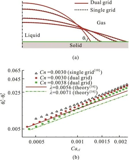
Fig.4 (Color online) Drop spreading on a flat substrate at θ e=15 o and O h = 0.1. (a) The snapshots of drop shapes at times t = 0, 0.5, 3 and 8. (b) The comparison between numerical results and the theoretical prediction in Eq.(19) in terms of versus C a cl, when the drop is app- roaching its equilibrium state
Snapshots of the drop at different times are shown in Fig.4(a), and the drop shape evolves gradually from a spherical cap with θi=60oto the one with θe=15o. The results on the dual-resolution grid are virtually overlapped with those on the single-resolution grid, implying that the effective slip length is more or less the same. Figure.4(b) provides a quantitative comparison of θaon a dual-resolution grid with different C n = 0.003 and 0.0038, along with the theoretical prediction of Eq.(19) with λ=0.0056 and 0.0071. The results suggest that the effect slip length on a dual-resolution grid can be approximated by λn= 1.9Cn, which is very similar to that using a geometric formulation of diffuse interface model on a single-resolution grid[5].
We examine the computational efficiency by comparing the computational time on a dual-resolution grid and a single-resolution grid with the same interface resolution, h = 0.004. Computations are performed on a node with the Intel Xeon CPU (2.50 GHz and 24 cores totally). The computational time required per time step is 0.174 s on a dual-resolution grid and 0.442 son a single resolution grid. This suggests that the use of the dual-resolution grid requires only 40% of the computational time required by the single-resolution grid.
2.2 Drop impact on a convex substrate
When a drop impacts on a convex substrate, the convexity of the substrate has significant effect on the dynamics of drop impact, leading to interesting flow phenomena such as detaching[13], rebounding[14]and spreading[15-17]. It is also reasonable to expect that the convexity of the substrate affects the occurrence of drop splashing. We conduct here the impact of a drop of diameter D on a convex substrate at an impact speed of U. The wettability of the substrate is represented by theequilibrium contact angleristic length and velocity, and the dimensionless group consists of the Weber number and Reynolds number.In the present study, we consider R e = 3000 and We = 324 and 441. The simulations are performed on both the dual and single resolution grid with h =0.0015, 0.003, 0.006 and 0.012.
The impact dynamics is shown in Fig.5, in terms of evolution of drop shapes on two different convex substrates: the Case A with curvature radius of 1.5D,and the Case B with curvature radius of 30D. In general, we can observe that a lamella appears at the front of the spreading of the liquid film on the substrate, and tends to detach from the substrate, e.g.,for <0.3t . In the insets of Fig.5, in the Case B a ring breaks up from the lamella, indicating the start of splashing, while in the Case A there is no breakup and the lamella eventually evolves into a rim. Palacios et al.[17]reported that dropsplashing occursat flat substrate at W e = 441 and R e = 3000. Our numerical results suggest that it is hard for a drop to splash on a convex substrate after impact. This is We > 4 .43Re0.53after impacting onto a flat substrate.Therefore, we would expect that impact of a drop on a particularly true for the Case A, in which the substrate is more convex than that in the Case B. Since the more convex the substrate, the less the conversion of drop momentum from the vertical to the horizontal direction, it is reasonable to expect that it is easier to suppress the splashing on a more convex substrate.
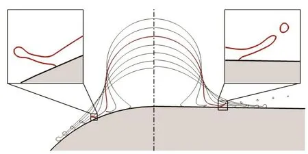
Fig. 5 (Color online) Snapshots of drop impact onto a convex substra te with curvature radius of 1.5D (left) and 30D (right)at W e = 441, R e = 3000 and θ e =120o,with time interval of 0.1. The insets show the zoom-in view of interface shape near the moving contact line at t =0.3

Fig.6 (Color online) Drop impact on a sphereat t = 0.8, and W e = 324, R e = 3000 and θ e =120o.Left:Compari- son between the resul ts on dual-resolutio n (red solid line) andsin gle-r esoluti on (black d ashed line)gridwith h = 0.003 ,an dright: theresults with differ ent h = 0.0015 (bluel ongdashed line), 0 .003 (redso lidlin e)a nd 0.006(greendash-dottedline).Theinsetsshowthezoom-in view of the rim

Table 1 Computational times (ms) per time step with diffe- rent h on a dual and single resolution grid
Figure 6 shows the comparison between the results at W e = 324 and R e = 3000 on a singleresolution grid with h = 0.003 and those on a dual-resolution grid with different grid sizes, i.e., h =0.0015, 0.003and 0.006. Obviously, the results obtained on both the grids are in good agreement.However, the computations on a dual-resolution grid cost nearly 60% less time than those on a single-resolution grid (see Table 1). It can also be seen in the inset on the right of Fig.6 the results converge with the mesh refinement.
3. Conclusions
We implemented the diffuse-interface immersedboundary method on the dual-resolution Cartesian grid, for the simulation of multiphase flows involving the moving contact line on a curved substrate. The performance of the method was examined by investigating the spreading of a drop on a flat substrate. It was found that the effective slip of the diffuse-interface immersed-boundary method on the dual-resolution Cartesian grid is proportional to the thickness of the diffuse interface, in consistence with previous work on diffuse interface model of moving contact lines[12,5]. In the impact dynamics of a drop impacting onto a convex substrate, the results on the dual-resolution and single-resolution grids were in good agreement. This implies that the use of dual-resolution grid has negligible effect on the interface resolution. We also observed that it is harder for a drop to splash on a convex substrate than a flat substrate. Numerical experiments showed that with same interface resolution, the computation time on the dual-resolution grid required roughly 40% of that on the single-resolution grid.
Acknowledgment
This work was supported by the Strategic Priority Research Program of the Chinese Academy of Sciences (Grant No. XDB22040103), the Fundamental Research Funds for the Central Universities and the China Postdoctoral Science Foundation (Grant No. 2017M612085).
[1] Jacqmin D. Calculation of two-phase Navier-Stokes flows using phase-field modeling [J]. Journal of Computational Physics, 1999, 155(1): 96-127.
[2] Ding H., Spelt P. D. M., Shu C. Diffuse interface model for incompressible two-phase flows with large density ratios [J]. Journal of Computational Physics, 2007, 226(2):2078-2095.
[3] Ding H., Yuan C. J. On the diffuse interface method using a dual-resolution Cartesian grid [J]. Journal of Computational Physics, 2014, 273: 243-254.
[4] Patil N. D., Gada V. H., Sharma A. On dual-grid level-set method for contact line modeling during impact of a droplet on hydrophobic and superhydrophobic surfaces [J].International Journal of Multiphase Flow, 2016, 81:54-66.
[5] Liu H. R., Ding H. A diffuse-interface immersed-boundary method for two-dimensional simulation of flows with moving contact lines on curved substrates [J]. Journal of Computational Physics, 2015, 294: 484-502.
[6] Ding H., Chen B. Q., Liu H. R. et al. On the contact-line pinning in cavity formation during solid-liquid impact [J].Journal of Fluid Mechanics, 2015, 783: 504-525.
[7] Zhu Y., Liu H. R., Mu K. et al. Dynamics of drop impact onto a solid sphere: spreading and retraction [J]. Journal of Fluid Mechanics, 2017, 824.
[8] Liu H. R., Gao P., Ding H. Fluid-structure interaction involving dynamic wetting: 2D modeling and simulations[J]. Journal of Computational Physics, 2017, 348: 45-65.
[9] Yarin A. L. Drop impact dynamics: Splashing, spreading,receding, bouncing [J]. Annual Review of Fluid Mechanics,2006, 38(1): 159-192.
[10] Sui Y., Ding H., Spelt P. D. M. Numerical simulations of flows with moving contact lines [J]. Annual Review of Fluid Mechanics, 2014, 46(1): 97-119.
[11] Hocking L. M. The spreading of a thin drop by gravity and capillarity [J]. Quartenly Journal of Mechanicsand Applied Mathematics, 1983, 36(1): 55-69.
[12] Ding H., Spelt P. D. M. Inertial effects in droplet spreading: A comparison between diffuse-interface and levelset simulations [J]. Journal of Fluid Mechanics, 2007, 576:287-296.
[13] Rozhkov A., Prunet-Foch B., Vignesadler M. Impact of water drops on small targets [J]. Physics of Fluids, 2002,14(10): 3485-3501.
[14] Mitra S., Sathe M. J., Doroodchi E. Droplet impact dynamics on a spherical particle [J]. Chemical Engineering Science, 2013, 100(2): 105-119.
[15] Bakshi S., Roisman I. V., Tropea C. Investigations on the impact of a drop onto a small spherical target [J]. Physics of Fluids, 2007, 19(3): 032102.
[16] Mitra S., Nguyen T. B. T., Doroodchi E. et al. On wetting characteristics of droplet on a spherical particle in film boiling regime [J]. Chemical Engineering Science, 2016,149: 181-203.
[17] Palacios J., Hernandez J., Gomez P. et al. Experimental study of splashing patterns and the splashing/deposition threshold in drop impacts onto dry smooth solid surfaces[J]. Experimental Thermal and Fluid Science, 2013, 44:571-582.
* Project supported by the National Natural Science Foundation of China (Grant Nos. 11425210, 11621202 and 11672288).
Biography: Hao-ran Liu (1989-), Male, Ph. D.
Hang Ding,
E-mail: hding@ustc.edu.cn
杂志排行
水动力学研究与进展 B辑的其它文章
- On the clean numerical simulation (CNS) of chaotic dynamic systems *
- BEM for wave interaction with structures and low storage accelerated methods for large scale computation *
- Flow-pipe-soil coupling mechanisms and predictions for submarine pipeline instability *
- On the hydrodynamics of hydraulic machinery and flow control *
- A 3-D SPH model for simulating water flooding of a damaged floating structure *
- Mechanism of air-trapped vertical vortices in long-corridor-shaped surge tank of hydropower station and their elimination *
