Application of linear active disturbance rejection control for photoelectric tracking system①
2017-09-25WangWanting王婉婷GuoJinJiangZhenhuaWangTingfeng
Wang Wanting (王婉婷), Guo Jin, Jiang Zhenhua, Wang Tingfeng
(*Changchun Institute of Optics, Fine Mechanics and Physics, Chinese Academy of Sciences, Changchun 130033, P.R.China)(**State Key Laboratory of Laser Interaction with Matter, Changchun 130033, P.R.China)(***University of Chinese Academy of Sciences, Beijing 100049, P.R.China)
Application of linear active disturbance rejection control for photoelectric tracking system①
Wang Wanting (王婉婷)②******, Guo Jin***, Jiang Zhenhua***, Wang Tingfeng***
(*Changchun Institute of Optics, Fine Mechanics and Physics, Chinese Academy of Sciences, Changchun 130033, P.R.China)(**State Key Laboratory of Laser Interaction with Matter, Changchun 130033, P.R.China)(***University of Chinese Academy of Sciences, Beijing 100049, P.R.China)
Dynamic characteristics and tracking precision are studied in the photoelectric tracking system and a linear active disturbance rejection control (LADRC) scheme is proposed for position loop. A current and speed controller is designed by a transfer function model,which is obtained by adaptive differential evolution. Model error, friction and nonlinear factor existing in position loop are treated as ‘disturbance’, which is estimated and compensated by generalized proportional integral (GPI) observer. Comparative results are provided to demonstrate the remarkable performance of the proposed method. It turns out that the proposed scheme is successful and has superior features, such as quick dynamic response, low overshoot and high tracking precision. Furthermore, with the proposed method, friction is suppressed effectively.
photoelectric tracking system, linear active disturbance rejection control (LADRC), generalized proportional integral observer, adaptive differential evolution
0 Introduction
The photoelectric tracking system has been widely applied for tracking moving targets precisely. Driven by direct current motor[1], photoelectric tracking system is considered as a high precision servo system. Considering the characteristics inherent in motor, the control system design represents a difficult and challenging problem. Low resonance oscillation may restrict greatly the closed loop bandwidth and gain of open loop. The miss distance delay caused by detector may make the system unstable[2]. The nonlinear factors, such as friction, model errors and external disturbance, might reduce tracking precision[3]. Therefore, an effective control strategy is particularly important for high tracking precision and fast response speed.
To solve the above problems, various control strategies have been proposed and developed in literature. Classical algorithms, such as proportional integral derivative (PID) and lead lag algorithm are still dominant even today for their low complexity, simplicity of implementation and strong robustness. These examples can be found in speed and acceleration delay compensation[1], predication algorithm[4], nonlinear PID[5], etc. However, most of the control strategies focus on improving tracking precision. Along with advances in intelligent control techniques, new methodologies have been proposed to achieve perfect performance. These approaches are fuzzy control[6], internal control[7]and adaptive backstepping control[8]. However, due to the factors, such as complexity of algorithms, computation burden and convergence speed, the high precision control performance is still difficult to be achieved when implementing these methods in practice.
Based on the realistic rethinking about the PID technology, active disturbance rejection control (ADRC) was first proposed by Han[9]in 1990s and has been shown to be an effective tool in dealing with dynamic uncertainties, disturbance, and nonlinearities. Traditional ADRC has been applied to solve practical control problems in several fields[10-13]. For the tracking system, ADRC method has been successfully applied to speed loop in photoelectric platform[14-16]. Experimental results show strong ability in disturbance rejection. However, all this proposed methods were designed without considering the position tracking precision.
Unlike traditional ADRC based approaches, the generalized proportional integral (GPI) observer[17]constitutes an effective manner of integral ADRC schemes. With GPI observer, the estimation accuracy can be improved greatly[18]. In order to achieve perfect dynamic performance at the same time improving the control precision, a linear ADRC (LADRC) based on GPI observer is put forward in this paper and applied directly to position loop. The control scheme is tested on practical photoelectric tracking system, showing excellent results for tracking moving targets. The proposed method not only greatly reduces the tracking errors, but also improves the dynamic performance both in overshoot and response speed.
1 Formulation problem and design of control system
A typical photoelectric tracking system consists of speed and position loop. In this paper, current loop is introduced to deal with disturbance and back electromotive force. The equivalent structure of a photoelectric tracking system is shown in Fig.1.

Fig.1 The equivalent structure of photoelectric tracking system
Considering the fact that all the parameters including load torque, inertia and motor parameters are uncertain and not measurable, thus to obtain precise mathematical model directlyis difficult. Moreover, a precise mathematical model plays an important role in control system design. Therefore, an effective parameter identification strategy is particular important.
To obtain the accurate transfer function model, an adaptive differential evolution (ADE) algorithm[19]is chosen to carry on parameter estimation with input and output data. Impulse signal is selected as input x(t). Output data y(t), such as rotating speed of motor and armature current, are obtained by experiments. Fourier transform is applied to obtain the amplitude-frequency characteristic[20], which is shown in
(1)
The amplitude-frequency characteristic from input voltage to output current |G(jω)|U-Iis shown in Fig.2(a), and the amplitude-frequency characteristic from input voltage to output speed |G(jω)|U-Vis shown in Fig.2(b).

Fig.2 Experimented and simulated results
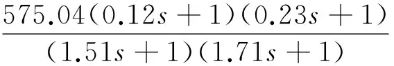
The transfer functions of voltage-current GU-Iand voltage-speed GU-Vobtained by ADE algorithm are shown in

(2)
GU-V=
(3)
To deal with disturbance and back electromotive force constant, a current controller is designed as

(4)
The controlled object of speed loop can be expressed as Eq.(5) by adjusting the gain of current controller properly.

(5)
The transfer function of speed controller using Lead lag control law is given by
(6)
Then the transfer function model of position open loop can be described as

(7)
Eq.(7) can be reduced to a typicalⅡsystem in low frequency, as shown in

(8)
The purpose of position controller is to obtain high tracking precision and fast response speed. However, considering the factors, such as friction, model errors, internal and external disturbance, it will be difficult to meet requirements of high tracking precision and fast response speed. It is for this reason that LADRC is adopted to effectively improve the tracking performance.
2 LADRC control strategy for position loop
Traditional ADRC[9]contains tracking differentiator (TD), feedback control law (FCL), and extended state observer (ESO), which is shown in Fig.3. The key of ADRC is to observe and compensate state variables, internal and external disturbances of the system through ESO, so that the system can restrain disturbance in real time[9]. To achieve accurate on-line estimations of all unknown disturbances, GPI observer is in charge of that estimation.

Fig.3 The principle of ADRC
Model errors, friction and disturbance are considered as ‘whole disturbance’, estimated and compensated by GPI observer in real time. Structure of the proposed method based on GPI observer is shown in Fig.4.
For the sake of simplicity and clarity, Eq.(8) is converted into state space form and is designed as
(9)
where, x1and x2denote the angle position and speed of the system. ξ represents the “total disturbance”, such as all the higher order terms neglected by linearization, model errors, external unknown disturbance, and so on.
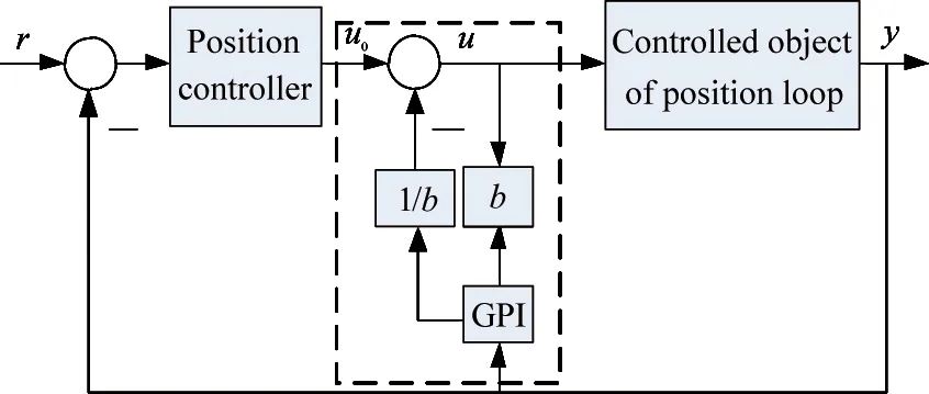
Fig.4 Structure of the proposed method based on GPI observer
GPI observer is designed in the form:
(10)
where, e represents the observer error, y1, y2are the estimates of position, speed. z1, z2are the estimates of disturbance. λ=[λ0, λ1, λ2, λ3]Tis the observer gains vector. φ(t, y) is the control input gain, which is considered as a constant gain in this paper.
Using bandwidth parameterization method[21]to tune the observer gain vectors and the equality is shown as
(s+ω0)4=s4+λ0s3+…+λ2s+λ3
(11)
where, ω0is the observer bandwidth, ω0should be selected properly to achieve satisfied performance.
Generally, a good control state can be obtained by combing TD with FCL. However, this approach will cause some problems in engineering applications, and it is not easy to achieve perfect performance[14]. Therefore, a linear control law is chosen in this paper. Using estimated value z1to correct the output of position controller u0, overall output u of LADRC is shown as
(12)
where, r is the input of tracking system.
By substituting Eq.(12) into Eq.(9), the system becomes

(13)
Obviously, the transfer function between u0and y is reduced to a cascade integrator.
3 Simulation analyses
In order to verify the perfect performance of LADRC, the control strategy is implemented in Matlab/Simulink platform and parameters are set as follows: The bandwidth of speed loop is 6Hz and the bandwidth of position loop is 1.62Hz. The LADRC parameters are set to be Kp-ADCR=5.29, Ki-ADRC=11.42. The simulation results of PI control[5]and traditional ADRC[16]are given for comparison, and the parameters are selected to make sure it has the same cut-off frequency with the proposed method.
3.1 Dynamic performance
Fig.5 gives the comparative results of step response. Regarding to the overshoot, both ADRC and LADRC can achieve satisfactory performance. It is seen in this case, the maximum overshoot of PI control is 60%, which is higher than ADRC and LADRC. From Fig.5, the settling time of LADRC is 0.7s, which is smaller than PI control and ADRC. Therefore, the LADRC method obtains the best dynamic performance.
3.2 Tracking performance
Fig.6 gives the comparative results of tracking performance in the closed loop control system for reference r=10sin(t) (°). As can be seen from Fig.6, the maximum tracking error of LADRC is 5.2′, which is lower than PI control and ADRC control. Obviously, the comparative results demonstrate the effectiveness of LADRC method.

Fig.5 The comparative results of step response

Fig.6 The comparative results of tracking errors
4 Experiment analyses
Photoelectric tracking system is established further to validate the correctness and effectiveness of the proposed strategy. The basic configuration of the experimental system is shown in Fig.7.
The experimental system consists of digital control board based on a 32-bit float-point TMS320C28335, the master control interface, the moving target, photoelectric tracking platform and so on. The control algorithm is downloaded and executed in the DSP controller. Experimental data are collected via the Code Composer Studio software and then processed in Matlab. Position displacement is obtained by absolute optical encoder, and the current is obtained by the current sensor. Under the experiment conditions, the miss distance, obtained by CCD sensor and processed by master control interface, is sent to DSP controller through SCI port. Lagrange interpolation is applied to deal with miss distance delay[1]. With position, speed and current closed-loop control, DSP controller adjusts the PWM according to the output of current controller, and generates direct voltage to regulate the photoelectric tracking platform.
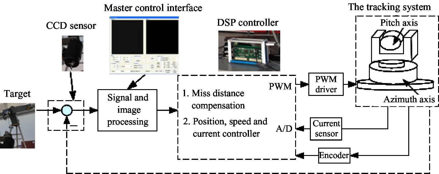
Fig.7 The basic configuration of the experimental system
Under the condition of experiments, the position, speed and current loop update in 0.001s, and the frequency of PWM is 20kHz. The experimental results of PI control[5]and traditional ADRC[16]are also given for comparison.
4.1 Dynamic performance
To verify the dynamic performance of LADRC, experimental results of acquiring a static target are comprehensively discussed.
Fig.8 gives the comparison results of tracking error, which is shown in pixel. From Fig.8(a) and Fig.8(b), for traditional ADRC strategy, the maximum rise time is 0.03s and the overshoot is 37%, for PI control, the maximum rise time is 0.072s and the overshoot is 60%; for LADRC strategy, the maximum rise time is 0.023s and the overshoot is 23%. Compared with PI control, the overshoot and rising time are reduced by over 60% and 65%.
From Fig.8, for PI strategy, the tracking error in steady state is controlled within 10 pixels. Considering the nonlinear factors existing in the tracking system, the control accuracy is not very high. For ADRC strategy, the tracking error in steady state is controlled within 5 pixels. For LADRC strategy, the tracking error in steady state is controlled within 3 pixels. The control precision is improved greatly, indicating that the proposed method has strong ability in disturbance rejection.
From the above analysis, it is clear that the LADRC method shows the best performance in terms of fast response speed, low overshoot and high control accuracy.

(a) The miss distance of target in acquisition mode

(b) The enlarged drawing of miss distance
4.2 The tracking performance
For the far moveable target, the equivalent velocity and acceleration of photoelectric tracking system are restricted lower than 10. On the other hand, without considering the friction compensation or failing to compensate for it may lead to large tracking error in low speed. To verify the friction rejection ability and tracking performance of the proposed method, experiments for tracking moving targets are performed in this section.
Fig.9 and Fig.10 give the comparative results of tracking error and its spectrogram with moving targets whose equivalent velocity are 0.91°/s and 2.23°/s. The vertical coordinate is shown in pixels. From Fig.9(a) and Fig.10(a), due to the friction, the tracking error of PI control is larger than that of ADRC and LADRC when speed decays to zero. The comparative results show that the friction is effectively reduced by ADRC and LADRC. Comparing with ADRC, LADRC method obtains the minimum tracking error, which indicates that the tracking precision can be improved significantly. From Fig.9(b) and Fig.10(b), the maximum amplitude spectrum of PI control is 15dB, the maximum amplitude spectrum of ADRC is 3.7dB, the maximum amplitude spectrum of LADRC is 2.1dB. Obviously, LADRC shows strong rejection in nonlinearity.

(a) The tracking error
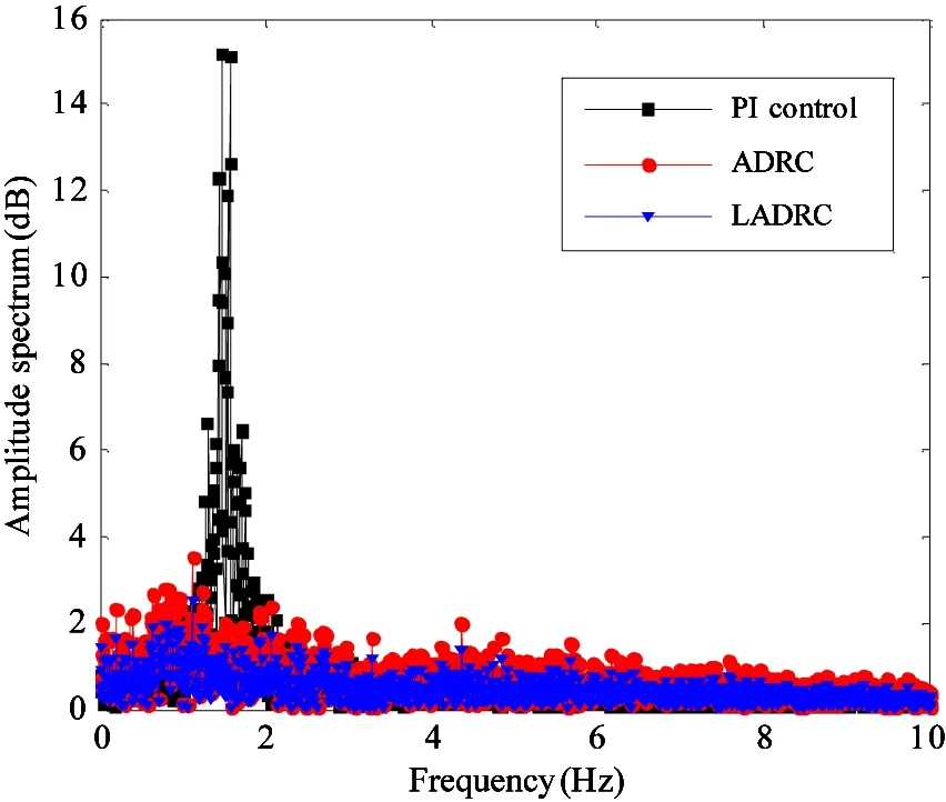
(b) The spectrogram of tracking error
Fig.9 The comparative results of tracking error and its spectrogram with moving targets whose equivalent velocity is 0.91°/s

(a) The tracking error

(b) The spectrogram of tracking error
Fig.10 The comparative results of tracking error and its spectrogram with moving targets whose equivalent velocity is 2.23°/s
5 Conclusions
Generally, a novel position control approach based on ADRC has been proposed and applied to deal with tracking problems. The unknown dynamics and the external disturbance are estimated and compensated by GPI observer in real time. Comparative results show that LADRC method significantly improves the tracking performance when applied directly to photoelectric tracking system. Compared with traditional methods, the proposed method shows high tracking precision, fast response speed and low overshoot. In the future work, it is believed that the application of the proposed method in tracking system can be further acknowledged.
Reference
[ 1] Wang J L. Study on TV Tracking System of O-E Theodolite to Track and Acquire Fast Moving Targets: [Ph.D dissertation]. Changchun: Changchun Institute of Optics, Fine Mechanics and Physics, Chinese Academy of Sciences, 2003. 9-16 (In Chinese)
[ 2] Tang T, Ma J G, Ren G, et al. Compensating for some errors related to time delay in a charge-coupled-device-based fast steering mirror control system using a feedforward loop. Optical Engineering. 2010, 49(7): 717-720
[ 3] Xia Y, et al. Application of active disturbance rejection control in tank gun control system. Journal of the Franklin Institute, 2014, 351(4): 2299-2314
[ 4] Li K Y, Tian F Q, Rong L. Equivalent combined control of photoelectric tracking and pointing system based on square-root cubature Kalman filter. Systems Engineering & Electronics, 2013, 35(7):1508-1513 (In Chinese)
[ 5] Li H, Ren C, Song L, et al. Application of combined controller based on CMAC and nonlinear PID in dual redundant telescope tracking system. In: Proceedings of the Conference on Software and Cyberinfrastructure for Astronomy III, Montreal, Canada, 2014. 91521:91521V1-6
[ 6] Liu L, Shen H H. Fuzzy-PID control for airborne optoelectronic stabilized platform. In: Proceedings of the 6th International Symposium on Advanced Optical Manufacturing and Testing Technologies: Optical System Technologies for Manufacturing and Testing, Xiamen, China, 2012. 8420: 84201H-84201H-6
[ 7] Li H W. Servo system of large telescope based on internal model PID control method. Optics and Precision Engineering, 2009,17(2): 327-332 (In Chinese)
[ 8] Ren Y, Liu Z H, Rui Z. DOB based robust adaptive backstepping control of compound-axis Opto-electronic tracking system. In: Proceedings of the 24th Chinese Control and Decision Conference (CCDC), Taiyuan, China, 2012. 2984-2988
[ 9] Han J Q. From PID to active disturbance rejection control. IEEE Transactions on Industrial Electronics, 2009, 56(3): 900-906
[10] Jiang T, Huang C, Guo L. Control of uncertain nonlinear systems based on observers and estimators. Automatica, 2015, 59: 35-47
[11] Ran M, Wang Q, Dong C, Stabilization of a class of nonlinear systems with actuator saturation via active disturbance rejection control. Automatica, 2016, 63: 302-310
[12] Zhao Z L, Guo B Z. On active disturbance rejection control for nonlinear systems using time-varying gain. European Journal of Control, 2015, 23: 62-70
[13] Xue W, Huang Y. Performance analysis of active disturbance rejection tracking control for a class of uncertain LTI systems. ISA Transactions, 2015, 58(5): 133-154
[14] Wang S, Li H W, Meng H R, et al. Active disturbance rejection controller for speed-loop in telescope servo system. Optics and Precision Engineering, 2011, 19(10): 2442-2449 (In Chinese)
[15] Li J Y, Fu C Y, Tang T, et al. Design of active disturbance-rejection controller for photoelectric tracking system on moving bed. Control Theory&Applications. 2012, 29(7): 955-958+964 (In Chinese)
[16] Li X T, Zhang B, Shen H H. Improvement of isolation degree of aerial photoelectrical stabilized platform on ADRC. Optics and Precision Engineering. 2014, 22(8): 2223-2231 (In Chinese)
[17] Ramírez-Neria M, Sira-Ramírez H, Garrido-Moctezuma R, et al. Linear active disturbance rejection control of underactuated systems: the case of the Furuta pendulum. ISA Transactions, 2014, 53(4): 920-928
[18] Zhang Y J, Zhang J, Wang L, et al. Composite disturbance rejection control based on generalized extended state observer. ISA Transction. 2016, 63(7): 377-386
[19] Gong W, Cai Z, Yang J, et al. Parameter identification of an SOFC model with an efficient, adaptive differential evolution algorithm. International Journal of Hydrogen Energy, 2014, 39(10): 5083-5096
[20] Wang G X, He Z. Control System Design. Beijing: Tsinghua University Press, 2009. 31-33 (In Chinese)
[21] Z G. Scaling and bandwidth-parameterization based controller tuning. In: Proceedings of the American Control Conference, Denver, USA, 2006. 4989-96
Wang Wanting, born in 1990. She is working on the Ph.D degree in Optical Engineering from State Key Laboratory of Laser Interaction with Matter, Changchun Institute of Optics, Fine Mechanics and Physics, Chinese Academy of Sciences, and the University of Chinese Academy of Sciences. She received her B.S. degree in Measurement & Control Technology and Instrumentations from North China University of Water Resources and Electric Power, Zhengzhou, China, in 2011. Her current research interest involves system identification and servo control.
10.3772/j.issn.1006-6748.2017.03.013
Supported by the National High Technology Research and Development Programme of China (No. 2015AA8082065) and the National Natural Science Foundation of China (No. 61205143).
To whom correspondence should be addressed. E-mail: wangwanting0907@163.com
on Aug. 22, 2016
杂志排行

High Technology Letters的其它文章
- Quantitative analysis of the performance of vector tracking algorithms①
- Simulation and experimental research of digital valve control servo system based on CMAC-PID control method①
- Structure design of gradient hard coatings on YG8 and their residual stress analysis by ANSYS①
- ZnO whiskers growth on the surface of Sn9Zn/Cu solder joints in concentrator silicon solar cells solder layer①
- Characterizing big data analytics workloads on POWER8 SMT processors①
- A leveling mechanism for the platform based on booms-constraint control of aerial vehicle①