A leveling mechanism for the platform based on booms-constraint control of aerial vehicle①
2017-09-25ZhangCuihong张翠红CaoXuepengJiaoShengjieYangBinWangGuanhongZhouZhaoqiang
Zhang Cuihong (张翠红), Cao Xuepeng, Jiao Shengjie, Yang Bin,Wang Guanhong, Zhou Zhaoqiang
(*School of Construction Machinery, Chang’an University, Xi’an 710064, P.R.China)(**National Engineering Laboratory for Highway Maintenance Equipment, Chang’an University, Xi’an 710064, P.R.China)
A leveling mechanism for the platform based on booms-constraint control of aerial vehicle①
Zhang Cuihong (张翠红)②***, Cao Xuepeng***, Jiao Shengjie***, Yang Bin**,Wang Guanhong**, Zhou Zhaoqiang**
(*School of Construction Machinery, Chang’an University, Xi’an 710064, P.R.China)(**National Engineering Laboratory for Highway Maintenance Equipment, Chang’an University, Xi’an 710064, P.R.China)
In order to achieve an automatic leveling function for work platforms of aerial vehicles with mixed-booms (MAV) in full elevating domain, an auto-leveling mechanism for the platform is proposed based on a control method of booms-constraint, where mixed-boom structures and elevating characteristics are considered. Three models of constraint strategies include non-constraint model, elevating constraint model and lowering constraint model, which is designed to meet the leveling requirements in full working extent. Through the hydro-mechatronic unified modeling, a virtual prototype model is set up based on the auto-leveling mechanism, and leveling performances of the platform are studied during booms elevating to the maximum working height and extent. Simulation results show that the control method of booms-constraint can realize auto-leveling of the platform under two typical working conditions, meanwhile a leveling deviation appears at the constrained point, but the platform inclination is adjusted in the permissible range. The control method does not only restrict booms’ freedom elevating to a certain extent, but also impacts the booms extending to the maximum working range. Experimental results verify that the auto-leveling mechanism based on booms-constraint control is valid and rational, which provides an effective technology approach for development of the platform leveling of MAV.
mixed-booms aerial vehicle (MAV), platform leveling, booms-constraint control, model simulating
0 Introduction
Aerial vehicles with mixed-booms (MAV) have dual advantages of articulating and telescoping booms with a large working range, flexible elevating, cross-barrier operations, environmental adaptability, etc.[1,2]. Automatic leveling approach of work platform, as one of the key technologies of MAV, is requested with large leveling angle, fast response and high leveling accuracy[3,4]. Flow distribution valve is used to parallel with the leveling circuit and the main one with compact and low-cost features[5], but the flow distribution varies with oil temperature, conducting fluctuations of supply flow-rate in the leveling procedure, so leveling stabilities become poor.
Generally, independent leveling apparatus or circuit achieves the level adjusting of the platform, including parallel four-links structures, hydrostatic equilibrium, combining movements of bars and chains, compound regulation of hydro-mechanical circuit, etc.[6]. These leveling systems although have good stability and high reliability, but the features of response and low accuracy make them difficult to meet requirements for the platform leveling of MAV in large operating range[7].
The method of electro-hydraulic leveling integrates with simple mechanism, high accuracy and fast response. The electro-hydraulic servo leveling having special manufacturing precision, high production cost, sensitive to fluid and high maintenance cost, is mainly used in the leveling system of large height fire trucks[8].
For MAV platform leveling, if movements of booms elevating are not constrained, the sum of angular displacement of all-booms exceeds 180°, while the maximum leveling angle output from electro-hydraulic leveling system is only 180°[9,10], which does not match with the leveling requirement.
1 Elevating features and leveling requirements
1.1 Boom structures and elevating features
A MAV has two-level telescopic booms and a small-jib, whose upper structures include turntable elevating booms consisting of down-boom (DB), upper-boom (UB), small-jib (SJ), work platform (WP), etc., shown as Fig.1. At the initial position, the upper-boom and the down arranged in parallel, and elevating angle displacement of other components compared to each initial state is shown as Table 1.
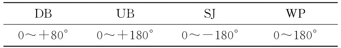
Table 1 Angular displacement range of each component
Note: Compared with the initial position, mark “+” is used when components turn counterclockwise, otherwise is “-”.
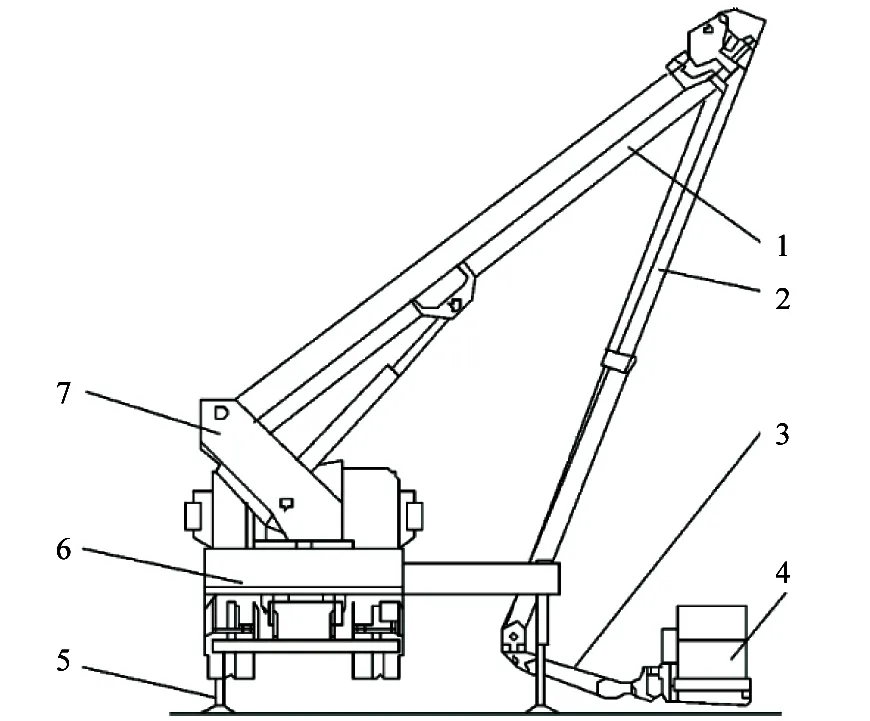
1. Down- boom; 2. Upper-boom; 3. Small-jib; 4. Work platform;5.Outriggers; 6. Chassis; 7. Turntable
1.2 Leveling requirements
Based on the structure features, leveling performances of platform hanged at the end of booms has the following requirements.
The output leveling-angle varies in a large scale. The elevating angle resulting from boom lifting reaches 260°, so large leveling angle output from leveling system is essential for balancing platform tilting caused by booms elevating.
High leveling precision is prerequisite. This parameter is the comprehensive reflection of stability and responsiveness. The platform inclination with horizontal plane shall not exceed 5° at any working position in the national standards for aerial vehicles[11].
2 Leveling solutions and component selection
2.1 Drive schemes of leveling system
According to elevating features, maximum swing angle for the platform is 180°, which cannot completely balance the inclination caused by booms elevating, and a displacement vacuum of 80° to leveling output still exists.
An auto-leveling mechanism for MAV named as booms-constrained control is proposed to adapt to the platform adjusting, and this method keeps platform horizontal by coordinating inputs of booms elevating with output of leveling system. The structures of leveling system are shown as Fig.2.
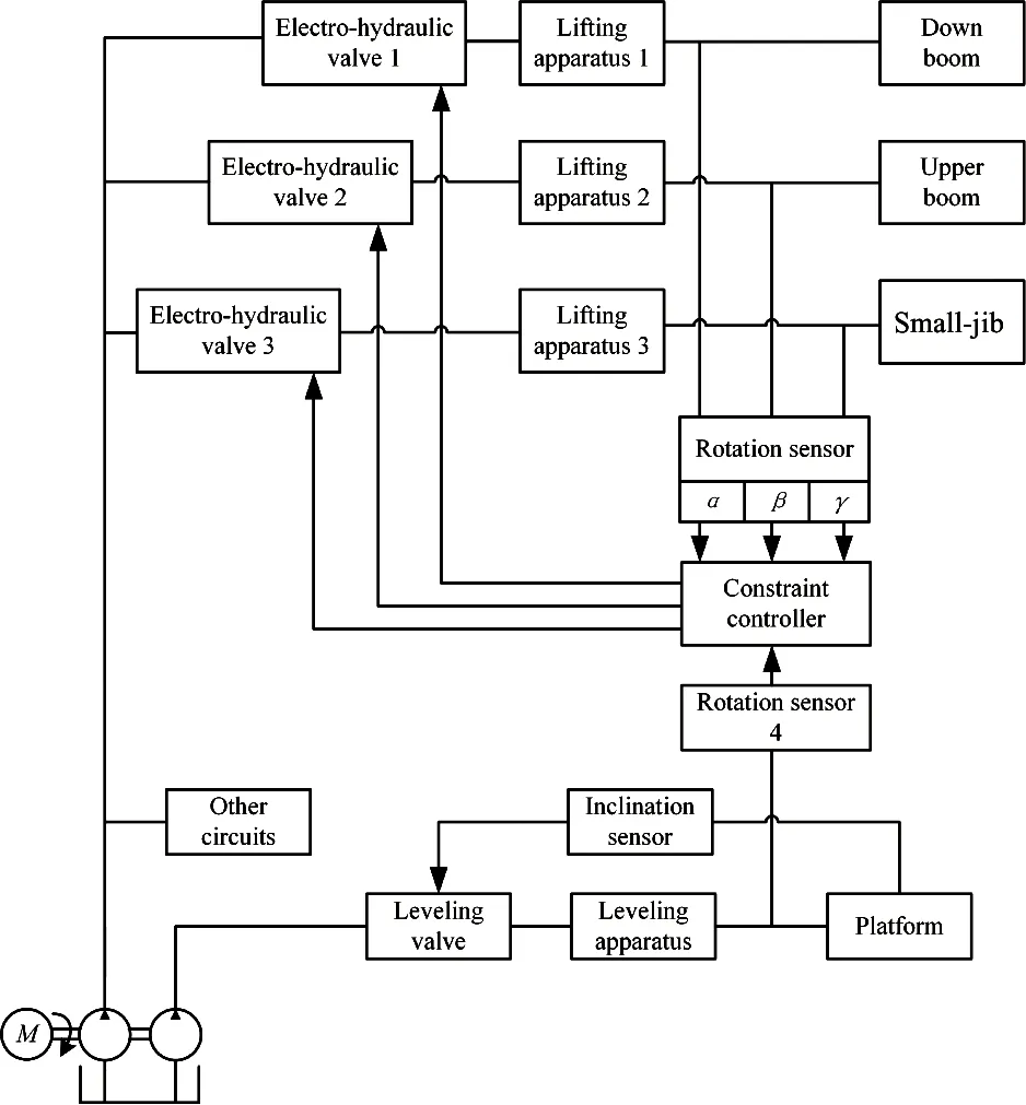
Fig.2 Structures of leveling system for MAV
One engine drives double-pump supplying pressure oil to leveling circuit of platform and elevating circuit of booms, respectively. In the former, the tilt signal detected by inclination sensor adjusts the opening of leveling valve, fluid through which pushes a swing of leveling apparatus, then they output leveling angle of the platform, and the inclination adjustment is done. In the latter, pressure fluid controlled by each electro-hydraulic valve drives elevating apparatus lifting, and makes three booms move, including down-boom, upper-boom and small-jib, thus platform elevating is executed. Rotation sensors 1~4 are used to detect swinging angles of three booms, and these signals are input to a constraint controller. The controller integrates and compares the sum of angles from booms elevating with leveling angle from leveling apparatus, and export corresponding signal enters electro-hydraulic valve to restrict boom elevating, and keeps the input from booms match with the output from leveling apparatus. Based on the above procedures, a real-time adjustment of inclination for the platform is realized under different elevation of booms.
2.2 Component selection
Taking practical applications of pumps into account, the main constant-displacement pump also supplies pressure oil to other circuits beside the elevating circuit, so a larger-displacement one should be selected. While an aided pump is dedicated to the leveling of platform, small displacement is enough. The picking of rated pressure needs to sum up driven requirements of each load, and complies with the pressure greater than the maximum working pressure of each circuit. Selections of hydraulic cylinder should comprehensively consider impacts of velocity ratio of telescopic cylinder, dynamic responses of valves and stability induced by ratio of length and diameter. The valves should have a fast response and good control accuracy, and whose parameters should match with the cylinder. The selections of main components are shown as Table 2~Table 4.
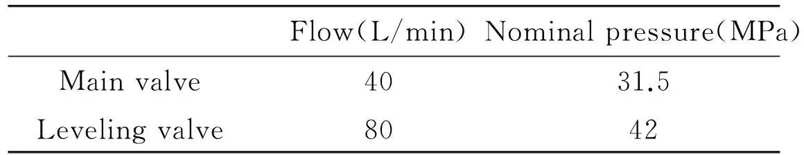
Table 2 Parameters of valves
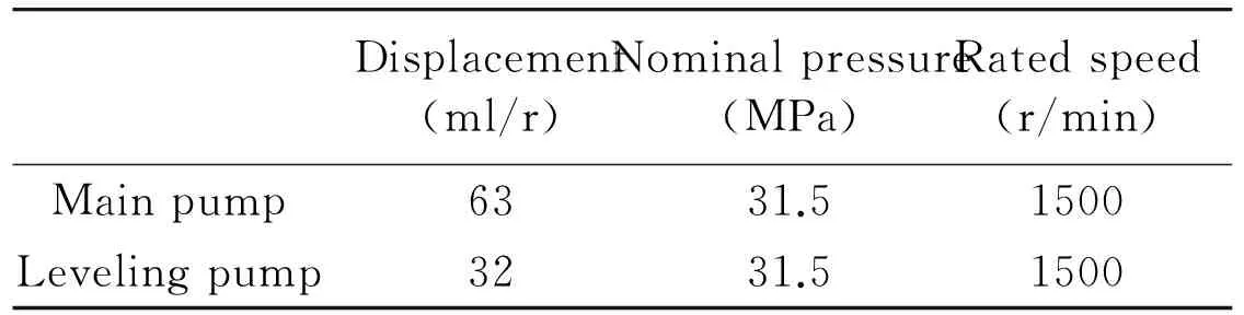
Table 3 Parameters of pumps
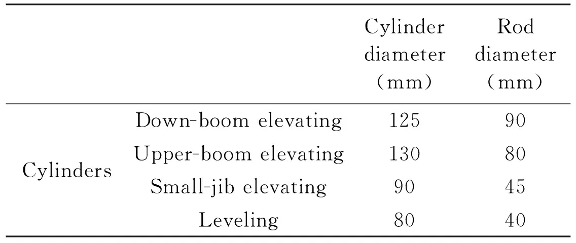
Table 4 Parameters of cylinders
3 Constraint strategies and control processes
3.1 Constraint strategies for booms elevating
(1) Non-constraint model
The sum of elevating angle from the three booms lifting equals φ=α+β-γ, and meets with φ∈(0°, 180°). In this case, the constraint controller does not restrict the control signals of each elevating boom input from integrated handles. Control relationships can be expressed as
If the sum φ∈ (0°, 180°), then the performing control is
Δih≠0, θo=δ, θi=φ-σ, θo=θi
(1)
where, θ0, θiare the platform swivel angle from leveling apparatus and the platform inclination induced by booms elevating, δ is the output angle of leveling system, α, β and γ represent each elevating angle of down-boom, upper-boom and small-jib, α is the platform inclination caused by flexible deformations of booms, Δihis a signal incensement of the solenoid valve controlling boom elevating.
(2) Elevating constraint model
The sum of elevating angle reaches the upper limit of leveling angle, and boom up-elevating is intended to continue. In this case, signals producing boom up-elevating are all constrained.
If the sum φ=180° and Δα>0 (Δβ>0 or Δγ>0), then the performing control is
Δihβ<0 or Δihγ<0, θo=δ,
θi=α+β-σ, θo=θi
(2)
where, Δiβ, Δiγare signal incensement of the solenoid valve controlling the elevating of down-boom and upper-boom, and negative value indicates the lowering of booms.
(3) Lowering constraint model
The sum of elevating angle reaches the lower limit of leveling angle, and a boom lowering is intended to continue. In this case, signals producing boom lowering are all constrained.
If the sum φ=0° and Δα<0(Δβ<0 or Δγ<0), then the performing control is
Δihβ>0 and Δihγ>0, θo=δ,
θi=α+β-σ, θo=θi
(3)
In the actual condition, when elevating the platform to a target height, it generally accompanies with switches and organic combinations among these three control strategies. The constraint controller coordinates and schedules appropriate control strategies according to the variations of booms elevating, and restricts or discharges the action of related booms, by which keeping leveling angle consistent with elevating angle of booms.
3.2 Control processes
At design stage of leveling system, a permissible range of platform inclination should be determined, such as |θ|<3°. Based on the above control strategies, leveling control processes are plotted as Fig.3. In this flowchart, the controls of booms restraints and platform leveling are executed synchronously.
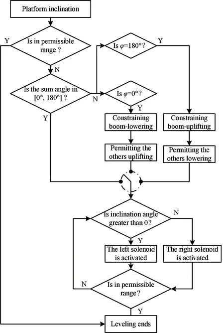
Fig.3 The leveling flowchart under booms constrained
4 Simulating analysis
4.1 Virtual prototype model
According to above control strategies, combining with booms structure of actual MAV, a virtual prototype model for auto-leveling system is built by the approach of hydro-mechatronics unified modeling in AMESim as Fig.4. As a typical mechanical electro-hydraulic simulating model, it comprises mechanical models of components, hydraulic models of elevating circuit and leveling system, and electrical model of constraint controller. Parameters of this virtual prototype are derived from a certain developed aerial working platform whose maximum working height could reach 37m. In which, fluids driving actuators are supplied by constant pressure source, and fluid compressibility and hose friction are considered, and backpressure 2MPa is set to prevent negative loads by relief valves in the return line and the value of other parameters is shown as Table 5.
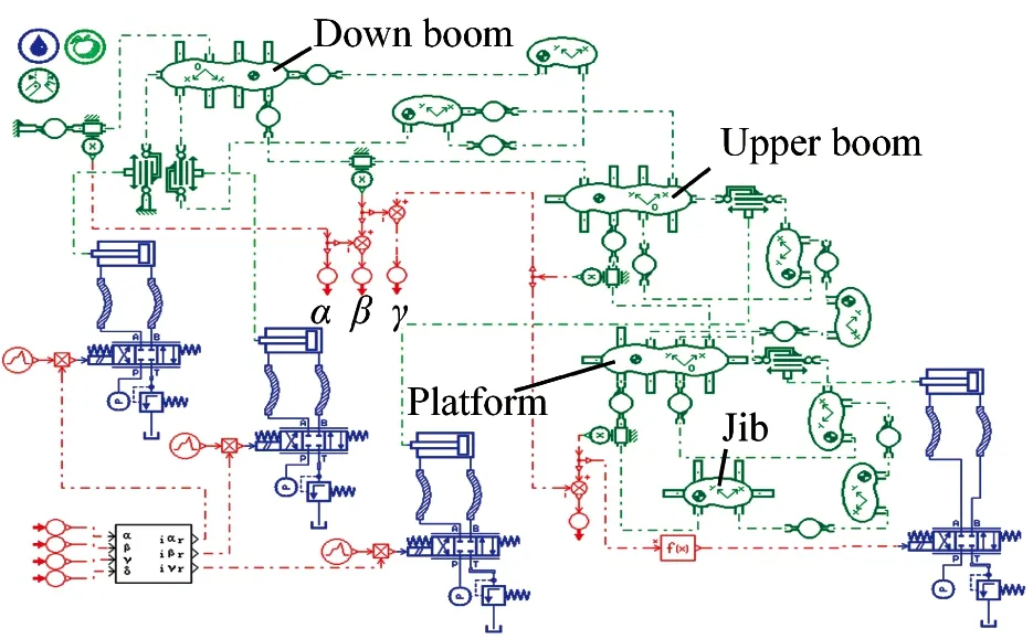
Fig.4 The virtual prototype model of auto-leveling system for aerial work platform
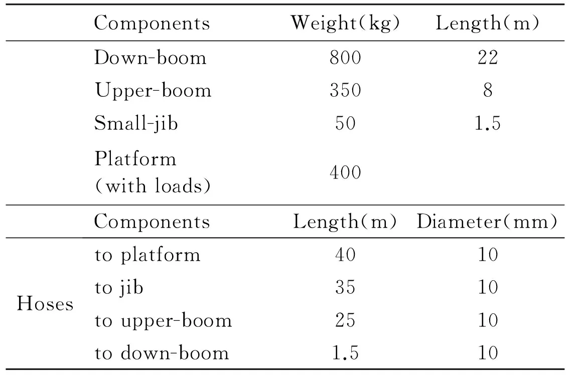
ComponentsWeight(kg)Length(m) Down-boom80022 Upper-boom3508 Small-jib501.5 Platform(withloads)400 ComponentsLength(m)Diameter(mm)Hosestoplatform4010tojib3510toupper-boom2510todown-boom1.510
4.2 Analysis of maximum-height working posture
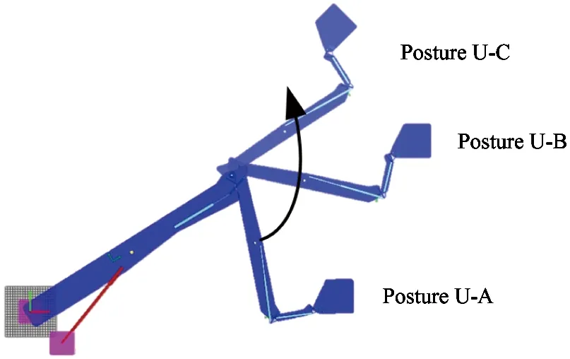
Due to the output working posture from the virtual prototype building in AMESim, obviously, the effectiveness of the proposed control strategies is validated. As shown in Fig.5(a), Posture U-B is the limited position, in which the output-leveling angle is 180°. Before the limited position, i.e. from Posture U-A to Posture U-B, the working platform is able to maintain the horizontal status. However, once the working position exceeds the limited position shown as Posture U-C, it is no doubt that the working platform will tip over subjected to the restricted output angle of the WP (seen as Table 1). While the proposed control strategies are applied to the control system, a reliable operation is obtained as Fig.5(b). When the working platform reaches the limited position, i.e. Posture E-A, controlling small-jib to move against elevating direction can release the leveling angle from 180° to 0°. This operation provides enough leveling angle to prevent the working platform from inclining during the elevating process from Posture E-B to Posture E-D.
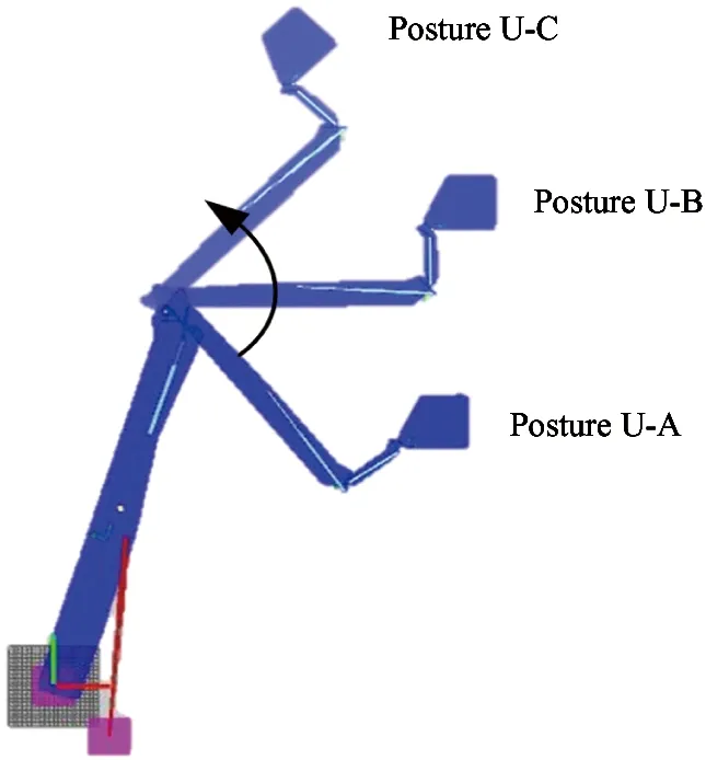
(a) Unable constraint control
(b) Enable constraint control
The specific performance of maximum-height posture operation is shown as Fig.6. The signals input to down-boom, upper-boom and small-jib from the handle are normalized as relative current value in [-1, 1], where the positive drives booms swinging as counterclockwise. The working conditions under booms-constraint strategies are symbolized “1” as non-constraint model and “2” as elevating constraint model.
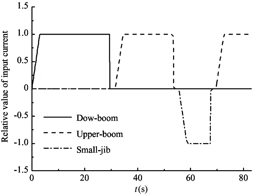
(a) Input signals to control valves for three booms
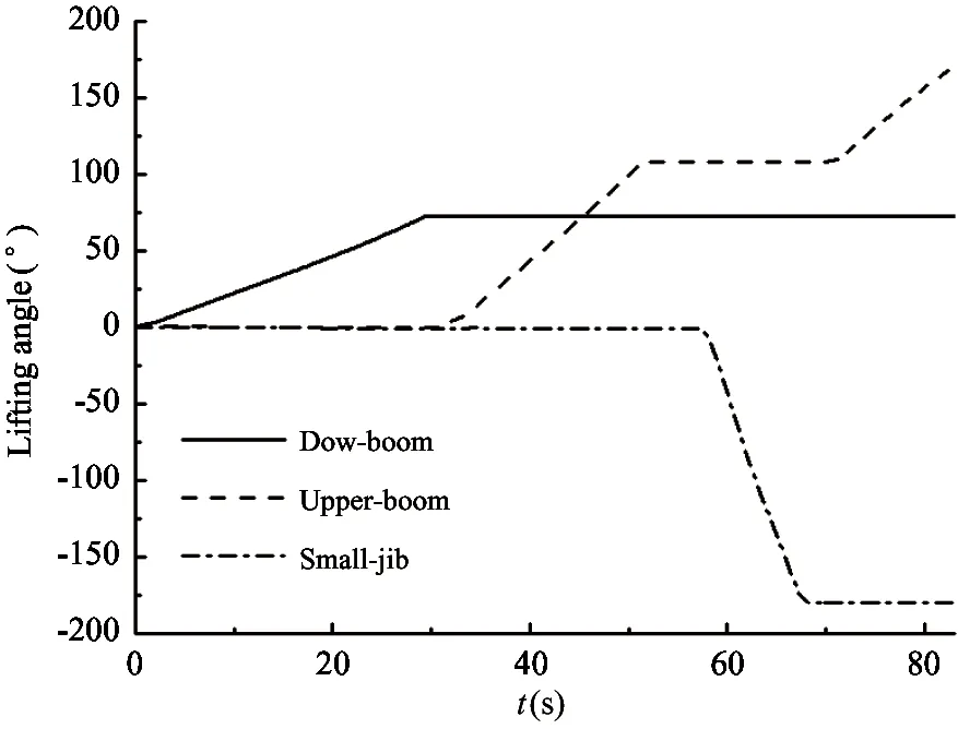
(b) Variations of lifting angles for three booms
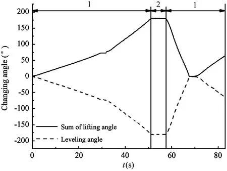
(c) The changes of total lifting angle and leveling angle
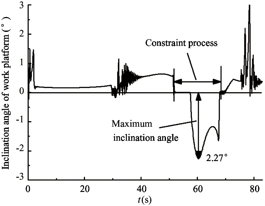
(d) Fluctuations of inclination angle for work platform
The variations of input signals and elevating angle of each boom are displayed as Fig.6(a) and Fig.6(b) by the constraint controller scheduling. Down-boom starts lifting at t=0, and rises to the upper limit 80° at t=29.5s, then upper-boom elevating begins until t=48.6s. At the moment, the sum of elevating angle gets 180°, and reaches the upper limit of leveling angle.As shown in Fig.6(c), the upper-boom elevating is restricted strictly, even though elevating signal is continuously maintained, the elevating angle remain 99.4°. In other words, the control strategy of boom constraint moves towards the constraint model “2” from the non-constraint “1”. With the small-jib lowering at t=55.6s, the sum gradually decreases from 180°, and output leveling angle reduces till zero simultaneously. At this stage, an abundant leveling angle is released by small-jib swinging. The constraint of upper-boom elevating is removed at t=69.5s, whose elevating angle continues to increase again until the maximum is 180°, and this control phase also belongs to the non-constraint “1”.
As shown in Fig.6(d), during the whole elevating process, the inclination angles of platform always change among the range from -3° to 3°. Especially, in the constraint process, the maximum inclination angle is 2.27°, which is a permissible safe range[11]. In addition, the fluctuations of inclination always appear at the point of start or stop of booms elevating and constraints imposed, but less than the permissible value. Besides, the fluctuations are inevitable because of the effect of long pipeline, overhanging beam and method of deviation adjustment. Therefore, based on the constraint control strategies of booms, the auto-leveling function of platform is achieved in the whole elevating domain. Furthermore, a ramp buffer continuing 3s are offered at booms startup in simulation, but some dithering still exists. So setting the buffer could not completely eliminate dither, other approaches should be also adopted.
4.3 Analysis of maximum-range working posture
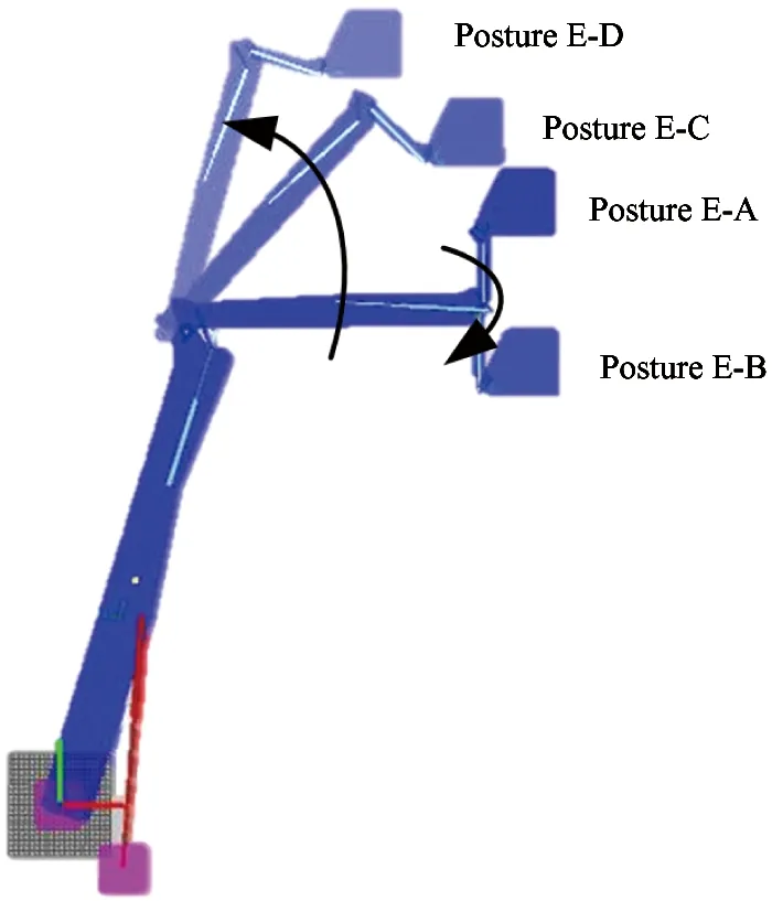
Similarly, the maximum-range working posture could be obtained in the AMESim simulation environment. In order to achieve the maximum-range working posture of platform, the proposed control strategy is implemented and a better effect is displayed as Fig.7. It is shown in Fig.7(a) that Posture U-B is the limited position. In the limited position, the output leveling angle is 180° so that the unable constraint control cannot keep the working platform in horizontal status from Posture U-B to Posture U-C, let alone reaching the maximum-range working posture as Posture E-D. Compared with unable constraint control, the enable constraint control could release the leveling angle from 180° to 0° in the Posture E-A, which is limited position in Fig.7(b). Then no matter the working platform elevates from Posture E-B to Posture E-C or arrives at the maximum-range pose, i.e. Posture E-D, it always maintains its safe status.
(a) Unable constraint control
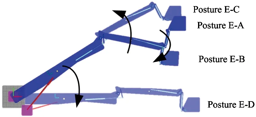
(b) Enable constraint control
For elevating to the maximum range, variations of input signals and elevating angle of each boom are displayed as Fig.8(a) and Fig.8(b) by the constraint controller scheduling. When t<43.2s, the sum of elevating angle does not exceed 180°, which matches with the range of leveling angle, and belongs to the non-constraint “1” as Fig.8(c). After about 2s elevating restricted, the small-jib lowers at t=55s and output leveling angle reduces reversely, at the same time, redundant leveling angle is generated. From t=57.8s, booms elevating enters into non-constraint model “1”, and the elevating of upper-boom keeps on the same position till reaches the upper limit 180°. At t>70s, the down-boom progressively lowers to zero.
The platform inclination varing in the whole elevating procedure is shown as Fig.8(d). Similarly, during the constraint process, the maximum inclination angle of working platform is 3.7°, which does not exceed the permissible range [-5°, 5°][11], so does the whole elevating domain, which validates the effectiveness of the proposed booms-constraint control. Although the inevitable inclination fluctuations also exist when constraint imposed because of the same reasons mentioned as the maximum-height working posture, the platform can reach the maximum-range working posture, i.e. Posture E-D, but the continuously non-constraint operation is unavailable.
Simulation results indicate that the constraints strategies regulate boom elevating or lowering by imposing or removing constraints, by which the sum of elevating angle is maintained in [0°, 180°], and matches with the range of leveling angle output from the leveling apparatus. Under constraint strategies of booms, the auto-leveling system adjusts platform inclination within [-5°, 5] in full elevating domain, although fluctuations appear at the point of startup or stop of booms elevating and constraints.
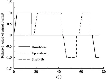
(a) Input signals to control valves for three booms
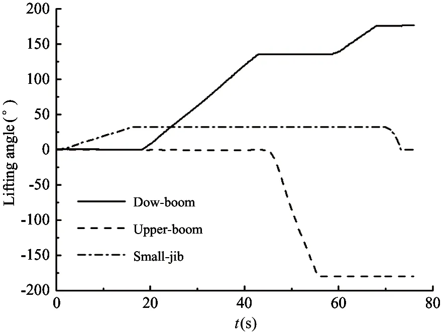
(b) Variations of lifting angles for three booms
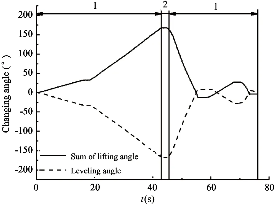
(c) The changes of total lifting angle and leveling angle
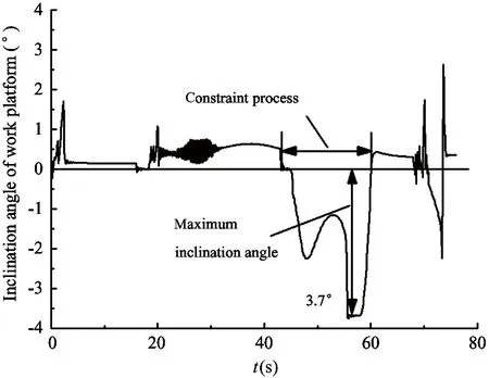
(d) Fluctuations of inclination angle for work platform
5 Conclusions
From mixed-boom structures of MAV and elevating features, an auto-leveling mechanism is proposed based on booms-constraint control. The drive scheme of leveling system is designed, and three control strategies are formulated to meet with the leveling requirements in full working domain, and the leveling flowchart is plotted.
Combining with booms structure of actual MAV, a virtual prototype model for auto-leveling system is built by the approach of hydro-mechatronics unified modeling in AMESim, in which fluid compressibility, hoses friction, and negative loads are all considered.
Simulation results confirm that the platform inclination is adjusted within permissible range in full elevating domain by regulating constraint strategies of booms and auto-leveling system, although some fluctuations appear when constraint imposed, which verify the auto-leveling mechanism based on booms-constrained control is effective and reasonable, and offers good references for the development of actual products.
[ 1] Zhang H, Huo Y L. Industry development and prospects of our country aerial vehicle. Construction Machinery, 2009, 12: 38-43 (In Chinese)
[ 2] Sun H X, Hou K, Jia Q X. Development, analysis and control of a spherical aerial vehicle. Journal of Vibroengineering, 2013,15(2):1069-1080
[ 3] Yang H G, Li G Y. Study on leveling method and control technology of a vehicle-bore platform. Machinery Design & Manufacture, 2008,12:134-136
[ 4] Schimaneck F, Merrifield D K. Aerial work platforms: safety, liability & the rental center. Professional Safety, 1998, 73(1): 25-28
[ 5] Cheng J S, Yuan W R, Yuan H S, et al. Self-level system of skid-steer loader based on AMESim. Journal of Jilin University (Engineering and Technology Edition), 2012, 42(6): 1390-1395 (In Chinese)
[ 6] Tian L M, Guo W B. Leveling mechanism of small size aerial vehicle with folding booms. Construction Machinery, 2003, 34(2): 20-22
[ 7] Krasucki J, Rostkowski A, Gozdek, et al. Control strategy of the hybrid drive for vehicle mounted aerial work platform. Automation in Construction, 2009,18(2): 130-138.
[ 8] Cao X P, Jiao S J, Cheng L, et al. Auto-leveling mechanism based on interaction of jip-work platform Journal of Chang’an University (Natural Science Edition), 2014, 34(4):184-190(In Chinese)
[ 9] Chen Y Q, Xu X H, Zhu H L, et al. Simulation research on the basic platform's automatic leveling system based on simhydraulics. Applied Mechanics and Materials, 2013.345:99-103
[10] Wang X, Zhang H M, Fang J B. Research on electro-hydraulic proportional leveling system of large aerial work platform based on Fuzzy PID. Applied Mechanics and Materials, 2011, 58-60: 221-226
[11] General Administration of Quality Supervision of China. GB/T 9465-2008,Vehicle-mounted mobile elevating work platform. Beijing:China Standards Press, 2008
Zhang Cuihong, born in 1982. She is currently working toward the Ph.D degree in Mechanical Engineering at Chang’an Univesity. She received her M.S. degree in Mechanical Design and Theory from Southwest Jiaotong University in 2008. Her research interests include mechanical electro-hydraulic technology and highway construction and equipment.
10.3772/j.issn.1006-6748.2017.03.014
Supported by the National Natural Science Foundation of China (No. 51509006),the National Key Technology R&D Program(No.2015BAF07B08) and Fundamental Research Funds for the Central Universities of Chang’an University (No. 310825161008).
To whom correspondence should be addressed. E-mail: caoxp2011@163.com
on Oct. 20, 2016
杂志排行

High Technology Letters的其它文章
- ZnO whiskers growth on the surface of Sn9Zn/Cu solder joints in concentrator silicon solar cells solder layer①
- Simulation and experimental research of digital valve control servo system based on CMAC-PID control method①
- Application of linear active disturbance rejection control for photoelectric tracking system①
- Structure design of gradient hard coatings on YG8 and their residual stress analysis by ANSYS①
- The rough representation and measurement of quotient structure in algebraic quotient space model①
- Characterizing big data analytics workloads on POWER8 SMT processors①