Simulation and experiment of starting transient flow field of the hydrostatic bearing based on dynamic mesh method①
2017-09-25ZhangYanqin张艳芹KongXiangbinGuoLiliYuXiaodongDaiChunxiShaoJunpeng
Zhang Yanqin (张艳芹), Kong Xiangbin, Guo Lili, Yu Xiaodong, Dai Chunxi, Shao Junpeng
(College of Mechanical & Power Engineering, Harbin University of Science and Technology, Harbin 150080, P.R.China)
Simulation and experiment of starting transient flow field of the hydrostatic bearing based on dynamic mesh method①
Zhang Yanqin (张艳芹)②, Kong Xiangbin, Guo Lili, Yu Xiaodong, Dai Chunxi, Shao Junpeng
(College of Mechanical & Power Engineering, Harbin University of Science and Technology, Harbin 150080, P.R.China)
A new method is developed to assess and analyze the dynamic performance of hydrostatic bearing oil film by using an amulets-layer dynamic mesh technique. It is implemented using C Language to compile the UDF program of a single oil film of the hydrostatic bearing. The effects of key lubrication parameters of the hydrostatic bearing are evaluated and analyzed under various working conditions, i.e. under no-load, a load of 40t, a full load of 160t, and the rotation speed of 1r/min, 2r/min, 4r/min, 8r/min, 16r/min, 32r/min. The transient data of oil film bearing capacity under different load and rotation speed are acquired for a total of 18 working conditions during the oil film thickness changing. It allows the effective prediction of dynamic performance of large size hydrostatic bearing. Experiments on hydrostatic bearing oil film have been performed and the results were used to define the boundary conditions for the numerical simulations and validate the developed numerical model. The results showed that the oil film thickness became thinner with the increase of the operating time of the hydrostatic bearing, both the oil film rigidity and the oil cavity pressure increased significantly, and the increase of the bearing capacity was inversely proportional to the cube of the change of the film thickness. Meanwhile, the effect of the load condition on carrying capacity of large size static bearing was more important than the speed condition. The error between the simulation value and the experimental value was 4.25%.
hydrostatic bearing, dynamic mesh, transient data, oil pad, UDF
0 Introduction
Compared with traditional hydrostatic bearings, hydrostatic bearings presented has a number of advantages, such as large bearing capacity, high calorific value, and high linear velocity. There is a trend in the modern mechanical engineering development to pursue high speed, high efficiency, high precision and automatic machining, in which new technology in hydrostatic sliding bearing plays an important role. One of the technical issues yet to be addressed is to accurately predict the dynamic performance of the hydrostatic bearing. The dynamic performance of hydrostatic bearing changes with the change of the oil film thickness after running for a period of time from the initial state. Numerical techniques for performance prediction using traditional classical lubrication theory need to be adapted to the new operation situation and engineering practice.
In the research of hydrostatic bearing, studies have been conducted on lubricating medium to improve environmental protection[1-5]. In 2012, Jagadeesha investigated the Reynolds equation with regards to the influence of the viscoelastic properties of the lubricant, and obtained a modified version of the Reynolds equation by using a finite element analysis method and iterative computation[6]. Also in 2012, Nicodemus, et al. studied the effect of the clearance oil film on the wear performance of the hybrid radial bearing system under the condition of micro polar lubrication, and established the Reynolds equation with variable flow velocity[7].
Xie, et al. analyzed the dynamic characteristics of a typical hydrostatic bearing. They proposed a simple method for determining the stability of the hydrostatic bearing by using a finite difference method to obtain 8 dynamic characteristic coefficients of the linear four-chamber hydrostatic bearing[8]. In 2009, Yu, et al. established a numerical analysis model of the large scale hydrostatic bearing fluid-solid coupling. Guo, et al. had carried on the theory research on the static and dynamic performance of the floating thrust bearing by using the hydrostatic and hydrodynamic techniques[9,10]. In 2010, Gao, et al. derived the dynamic performance of the rectangular static pressure guide which was based on the previous analysis of the hydrostatic bearing of the circular guide rail. Wu and Tao studied the static performance of the hydrostatic bearing used in gas lubrication, and obtained the relationship curve on the supporting performance. Xia, et al. carried out the modal analysis of the hydrostatic bearing in the gear shaping machine by using the finite element method[11-13]. In 2011, Wang studied the static and dynamic performance of the radial thrust bearing. He got the distribution of gas velocity and pressure in the bearing as film by using the software of Fluent to calculate, and carry out experiments[14]. In 2012, Zhou, et al. studied the hydrodynamic thrust bearing to evaluate its performance at different speeds[15]. In 2011 and 2013, Yu, et al. proposed that the fluid flow of the oil film of the hydrostatic thrust bearing had a significant effect on the lubrication performance, which was concluded that the oil chamber and oil film were laminar flow[16-19]. In 2009 and 2011, Shao used the finite element method and finite volume method to calculate the flow field of the oil film of large scale hydrostatic bearing, and revealed the flow law of oil film of the hydrostatic bearing by considering the influence of variable viscosity and centrifugal force[20,21].
From the above, it can be seen that research is mainly focused on radial bearing and hydro-hybrid bearing. However, few studies have been reported on hydrostatic bearing with multiple oil pads, especially on the transient flow field of the hydrostatic bearing based on dynamic mesh method. In this paper, under three operating conditions, i.e. the no-load, load and full load, oil film pressure field of large scale hydrostatic bearing in the transient state is investigated and the bearing capacity of the hydrostatic bearing is derived. The research results provide valuable theoretical basis for improving machining accuracy and work efficiency of the heavy hydrostatic thrust bearing.
1 Model of oil pad
Hydrostatic bearing is the use of special oil supply system, and leads lubricating oil with a certain pressure through the oil hole into the static pressure cavity of the hydrostatic bearing. The hydrostatic bearing system diagram is shown in Fig.1 and the parameters in the picture are the main parameters of the hydrostatic bearing, including geometric structure parameters of the hydrostatic bearing, design parameters (W0, P0, h0, Q0, T0) and working state parameters (W0+ΔW, Pr, h(t), Q(t), T(t)) of the hydrostatic bearing.
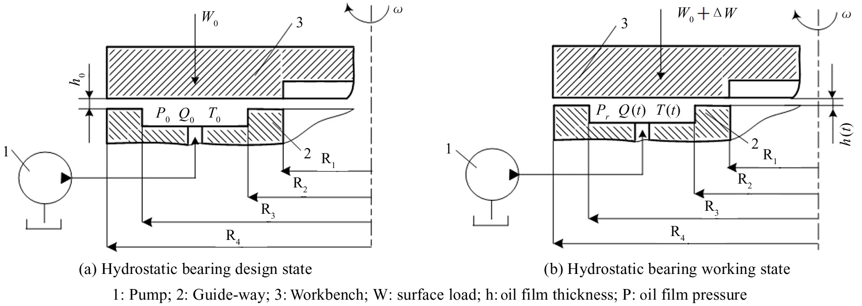
Fig.1 Hydrostatic bearing system
The clearance oil film of the hydrostatic bearing investigated in this work is of the lubrication mode of ring type oil cushion. A total of 24 oil cavities are included on the circumference, and they show a periodic symmetric distribution. Based on the practical industrial application, a 3D model of the large scale hydrostatic bearing gap oil film is modeled. The three dimensional model of the clearance oil film of the hydrostatic bearing is shown in Fig.2 which includes oil cavity, land, return chute, oil film, oil filler hole and other components.
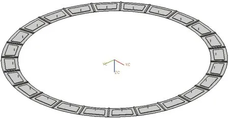
Fig.2 Hydrostatic bearing oil film 3d model
2 Transient mathematical model of the hydrostatic bearing oil film
A single oil pad structure of allergen scale hydrostatic bearing is shown in Fig.3 and the effective bearing area is shown in the picture as the headed area, where R1, R2, R3, R4, φ1, φ2are the structure dimensions of the round guide.
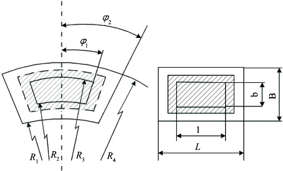
Fig.3 A single oil pad structure size
Analysis of the bearing capacity: The bearing capacity of large scale hydrostatic bearing is the external load that can be carried out by the oil film pressure acting on the surface under a certain oil film thickness, and the oil film thickness must make the oil pad fully covering the surface of the supporting parts. Under the same working condition, the more external load it can afford, the greater load-carrying capacity it has[22].
For the sector oil cushion, under the influence of the initial design load, the oil film thickness is hoand the oil chamber pressure expression is as
(1)
The bearing characteristics equation is

(2)
In the running process of the hydrostatic bearing, the bearing capacity of the hydrostatic bearing is influenced by the rotating speed of the working table and running time. When the speed is higher or the running time is longer, the bearing temperature will be raised, it will reduce the viscosity of the lubricating oil, and the lubricating oil resistance of sealing oil side outlet decline, that will decrease the bearing capacity of the hydrostatic bearing, and the oil film thickness becomes thinner.
The oil film thickness in the initial state of the hydrostatic bearing is h0when feeding oil by the static pressure. When the static pressure workbench rotates, as the oil film shear heat causes the clearance oil film of the hydrostatic bearing to become thin, the rotary table is moving down. The instantaneous oil film thickness of running state is h(t). Film thickness is
h(t)=h0-Δh(t)
(3)
where, h0is the initial film thickness, Δh(t)is the workbench shift distance.
When the rotating table is added to force Δp, the workbench will decline, oil film thickness becomes thin, and a new expression of the oil cavity pressure was derived under equilibrium condition as follows:
(4)
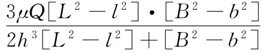
The running transient equation of the bearing capacity of the hydrostatic bearing is

(5)
where, μ is the dynamic viscosity of lubricating oil, h(t) is the instantaneous oil film thickness, Q is the fuel delivery, R1, R2, R3, R4, φ1, φ2are the structure dimensions of the static pressure guide.
From Eq.(5), one can see that the bearing capacity not only depends on the geometrical structure size of the oil cavity of the static pressure guide and oil seal edge, but also on the oil film thickness and the viscosity-temperature characteristics of the oil.
3 UDF procedure and boundary conditions
In order to express the regional division of the hydrostatic bearing fluid grid more clearly, the C-C profile of a single oil pad in Fig.4 is taken to provide a flow chart of oil film in Fig.5. The static area (stationary) and deformation region (deforming) of the large scale hydrostatic bearing gap oil film are indicated in the figure, where the upper surface of the oil film is the rotating wall (moving-wall), the moving-wall is the contact surface between the oil film and the working table. The oil film thickness varies with the rotating speed of the working table, the bearing capacity and the viscosity of the lubricating oil.
Fig.4 Hydrostatic bearing oil film model
Fig.5 Oil film dynamic grid locale
In order to determine the velocity and position of the boundary of oil film upper wall, this paper uses the DEFINE_CG_MOTION macro function in the dynamic grid technique, and determines the function of viscosity temperature property of the selected lubricating medium by the program.
UDF procedures are as follows:
#include
#include “udf.h”
# define NUM_CALLS 3
# define Zone_ID_moving_wall_zhuan5
DEFINE_CG_MOTION(wall_move,dt, cg_vel, cg_omega, time, dtime)
{
if (time<=8.0)
cg_vel[2]=-0.00001;
else
cg_vel[2]=0.0;
}
DEFINE_PROPERTY(cell_viscosity, cell, thread)
{
real mu0=3.5665E31;
real temp0=300;
realmu_lam;
real temp=C_T(cell,thread);
if(temp<300)
mu_lam=mu0;
else
mu_lam=mu0* pow( temp, -13.22838);
returnmu_lam;
}
4 Numerical calculation and analysis of oil film
The bearing capacity of the bearing is reflected by the pressure field of large scale hydrostatic bearing gap oil film. Based on theoretical analysis, the dynamic meshing technique is used to analyze the transient oil film as a function of time. The load bearing of the large scale hydrostatic bearing is evaluated under three operating conditions, i.e. no-load, load and full load. The loads are 0t, 40t, and 160t respectively. The oil film bearing capacity was evaluated in the transient state under the speeds of 1r/min,2r/min, 4r/min, 8r/min, 16r/min, 32r/min, respectively. The transient calculation results of the gap oil film pressure field of the hydrostatic bearing are shown in Fig.6, respectively. Typical results from rotating speed of 8r/min are shown here, and calculation results under other rotating speed conditions are provided in the following results analysis curve diagram.
From the simulation results of the transient distribution of the oil film pressure field, which are carried by large scale static pressure bearing under three operating conditions, no-load, load and full load, and the speed of 1r/min, 2r/min, 4r/min, 8r/min, 16r/min, 32r/min, the change curves of the transient pressure of oil film in different loading conditions are derived when the rotating speed is 8r/min, as shown in Fig.7, and the change curves of the transient pressure of oil film in different rotating speed conditions are also got when the load is 40t, as shown in Fig.8.
From the results of the pressure field of the large size hydrostatic bearing gap oil film in Fig.6, it can be seen that the oil film pressure distribution laws at different time are similar, and they all are the area where the oil chamber pressure is the highest, then the pressure value decreases gradually along the fluid domain of the four sides sealing oil, and the pressure distribution law is consistent with the pressure distribution of a single oil pad under the theoretical study, which is also consistent with the actual operating conditions and boundary conditions.
Examining the change curve of the transient pressure value of the static pressure bearing under different conditions in Fig.7 and Fig.8, it is known that with the increase of the operating time of the table, the film thickness becomes thinner and the pressure value of the oil chamber increases, and then, the oil film rigidity increases.
Fig.6 Different time oil film pressure field in 40t load condition (Unit: Pa)
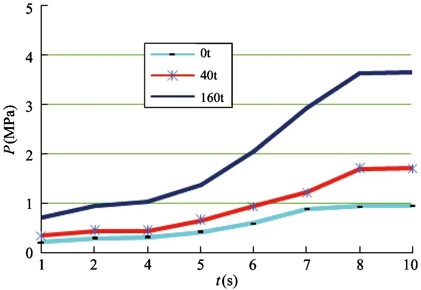
Fig.7 Transient pressure of oil film in different loading conditions
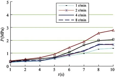
Fig.8 Transient pressure of oil film in different rotating speed conditions
For the impact of load and speed on the oil cavity pressure, the oil cavity pressure increases with the increase of load and speed, but at the same time, load factor influences much more on the oil cavity pressure of the large scale static bearing capacity than speed does.
5 Experimental research on multiple oil pad hydrostatic bearing
The large scale constant current static pressure bearing is used for the model of DVT1000 x 50/150Q-NC ten-meter double column vertical CNC lathe. The main technical parameters of the lathe are shown in Table 1, and the large scale hydrostatic bearing system is shown in Fig.9.
The total weight of the machine tool is 380t, among which, the weight of the rotary table is 62t, and the base weight of a circular rail with a multi pad is 37t.The rotating speed of the working table is continuously variable, and its material is grey cast iron HT300, and the guide plate of the base plate is made of aluminum alloy, and the lubricating oil is used in the hydraulic oil of 46.
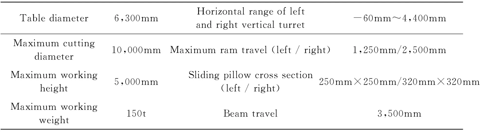
Table1 DVT1000×50/150 Q-NC main technology parameter
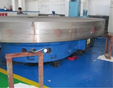
Fig.9 Large scale hydrostatic bearing system
Around the large size hydrostatic bearing base, there are 24 dimensions of the same oil pad which is a periodic symmetric arrangement, and in the experimental study, the rotation of working is counterclockwise. Since the pressure sensors mainly capture the pressures of the pressure oil chamber, the sensor is installed in the oil chamber, and taking into account the small overturning of the operating table, the three oil chambers are arranged in the circumferential direction of 120 degrees. The average value from the three sensors measured is taken as the experimental data of the final pressure value. The specific sensor layout scheme is shown in Fig.10.
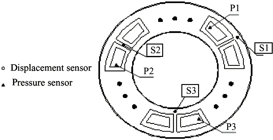
Fig.10 Sensor layout diagram
The test system for the oil film performance parameters of the large size hydrostatic bearing consists mainly of a thin-film thickness sensor, an oil film pressure sensor, an oil film temperature sensor, secondary instrument, data acquisition system and data post-processing system. In the experimental process, data of the experiment are processed by industrial computer. The data acquisition and processing system is shown in Fig.11.
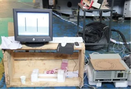
Fig.11 Oil film performance parameter data post-processing system
In the experimental study of the large size hydrostatic bearing oil film pressure, six loading conditions are tested, i.e. 0t, 20t, 40t, 60t, 80t, and 100t. The six loading conditions are combined with the workbench rotating speed of 1r/min, 2r/min, 4r/min, and the three pressure sensors are arranged in the same position of the three oil chambers which are 120 degrees apart from each other.
After the operation of the bearing becomes stable, the test data are recorded, and the average value of the measured data of the three sensors is used as the final experimental data. The hydrostatic bearing oil film pressure test results under different external loads are shown in Fig.12.
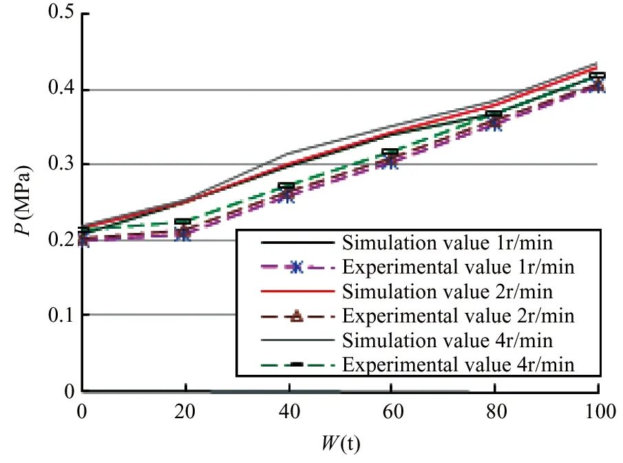
Fig.12 Hydrostatic bearing oil film pressure test results
The curves of the hydrostatic bearing oil film pressure test results show that the pressure of the oil film increases with the increase of the external load, and when making a vertical comparison of the test values of rotating speed in 1r/min, 2r/min and 4r/min, it is found that the effect of rotating speed on oil film pressure is small. As the effects of rotational speed on the pressure of oil film are mainly derived from the dynamic pressure which is caused by the rotation of the working table, which shows that the dynamic pressure effect of the large size hydrostatic bearing under the three rotating speed is very small.
The simulation value is compared with the experimental value. It is well known that experimental value is smaller than simulation value, the error between the simulation value and the experimental value was 4.25%. The difference may come from the oil pad difference due to the machining accuracy of the working table and the loss or leakage of the hydraulic system. Simulation results agreed well with theoretical and experimental research results.
6 Conclusions
A new numerical modeling technique for analyzing the dynamic performance of the hydrostatic bearing oil film by using the multi-layer dynamic mesh technique is proposed. This method improves the calculation accuracy, and uses C language to compile the hydrostatic bearing a single oil pad oil film UDF program. The numerical simulation results agreed well with the experimental results, and it shows the efficiency of the method in the calculation of the hydrostatic bearing oil film.
Transient data of the oil film bearing capacity of large size hydrostatic bearing are acquired through transient simulation of the oil film in the large scale hydrostatic bearing running under no-load, a load of 40t, a full load of 160t and the rotating speed of 1r/min, 2r/min, 4r/min, 8r/min, 16r/min, 32r/min, a total of 18 working conditions. Through this study, it is concluded that: with the increase of the operating time of the hydrostatic bearing workbench, the oil film thickness becomes thinner and the oil cavity pressure increases, and the increase ratio is inversely proportional to the cube of the change of oil film thickness. At the same time, the load factor of large scale static hydrostatic bearing oil cavity pressure is much bigger than speed impact on the oil cavity pressure.
[ 1] Novidov E A, Shitikov I A. Characteristics of hydrostatic thrust bearing. Chemical Petroleum Machinery, 2004,4:23-26
[ 2] Nada G S, Osmab T A. Static performance of finite hydrodynamic journal bearings lubricated by magnetic fluids with couple stresses. Tribology Letters, 2007, 27(3):261-268
[ 3] Nicodemus E, Rajasekhar, SharmaSatish C. Influence of wear on the performance of multirecess hydrostatic journal bearing operating with micro polar lubricant. Journal of Tribology, 2010,132(2):1-11
[ 4] Yuki N, Shigeka Y, Kei S. Numerical investigation of static and dynamic characteristics of water hydrostatic porous thrust bearings. International Journal of Automation Technology, 2011,5(6):773-779
[ 5] Go O, Shigeki O, Akinori Y. Numerical study on constant-flow hydrostatic water bearing for a machine-tool table. Advanced Materials Research, 2011,325:357-362
[ 6] Jagadeesha K M, Nagaraju T, Sharma S C, et al. 3D surface roughness effects on transient non-Newtonian response of dynamically loaded journal bearings. Tribology Transactions, 2012,55(1):32-42
[ 7] Nicodemus E, Rajasekhar, SharmaSatish C. Performance characteristics of micro polar lubricated membrane-compensated worn Hybrid journal bearings. Tribology Transactions, 2012,55(1):59-70
[ 8] Xie P L, Chen L, Duan X Y. Dynamic performance analysis of a typical hydrostatic journal bearing. China Mechanical Engineering, 2005,16(19):1712-1715 (In Chinese)
[ 9] Yu X J, Wang J X, Li Y. Study of fluid-solid simulation on the large-scale hydrostatic bearing of hollow coaxial. Materials Science Forum, 2009,628 629:281-286
[10] GUO H, Lai X M, Wu X L, et al. Performance of flat capillary compensated deep/shallow pockets hydrostatic/hydrodynamic journal-thrust floating ring bearing. Tribology Transactions, 2009,52 (2):204-212
[11] Gao D R, Zheng D. Theoretical analysis and numerical simulation of dynamic characteristics of hydrostatic guides for heavy NC machinetool. In: Proceedings of 2010 International Conference on Information Engineering, ICIE, Beidaihe, China, 2010. 114-117
[12] Wu D Z, Tao J Z. Analysis of static performance of porous graphite aerostatic thrust bearing. China Mechanical Engineering, 2010,21(19):2296-2301 (In Chinese)
[13] Xia M M, Li L J, Zhan C S. Modal analysis on liquid hydrostatic bearing of gear shaping machine based on ANSYS. Mechanical Research & Application, 2010,(1):94-95(In Chinese)
[14] Wang S F. Analysis on the static and dynamic characteristics of radial thrust aerostatic bearing: [Master Degree Dissertation]. Harbin: Harbin Institute of Technology, 2011. 43-45 (In Chinese)
[15] Zhou Q, Hou Y, Chen R G. Experimental research on compliant foil thrust bearings for high speed thrbine expander. Journal of Xi’an Jiaotong University, 2012,46(11):1-4 (In Chinese)
[16] Yu X D, Gao C L. Research on lubrication performance of high-speed heavy-duty hydrostatic thrust bearings. China Mechanical Engineering, 2013,24(23):3230-3234 (In Chinese)
[17] Yu X D. Research on pressure field of multi-pad annular recess hydrostatic thrust bearing. Journal of Donghua University (English Edition), 2013,30 (3): 254-257
[18] Yu X D, Qiu Z X, Li H H. Lubrication performance and velocity characteristics of a multi-oil-pad hydrostatic thrust bearing with a sector-shaped cavity. Journal of Engineering for Thermal Energy and Power, 2013,28 (3), 296-300 (In Chinese)
[19] Yu X D. Research on lubrication performance of super heavy constant flow hydrostatic thrust bearing. Advanced Science Letters, 2011,4:2738-3741
[20] Shao J P, Zhang Y Q. Numerical simulation analysis of sector and circular oil recess temperature field of heavy hydrostatic. Journal of Hydrodynamics(Ser.A), 2009,24(1):119-123 (In Chinese)
[21] Shao J P. The effect of oil cavity depth on temperature field in heavy hydrostatic thrust bearing. Journal of Hydrodynamics, 2011, 123(5):676-680
[22] Ding Z Q, Design of Fluid Hydrostatics Support. Shanghai: Shanghai Scientific and Technological Publishing, 2004 (In Chinese)
the Ph.D degree in the Specialty of Machinery Manufacturing and Automation from Harbin University of Science and Technology in 2009. She is an associate professor. She has been engaged in the teaching and researches in the NC Machine Key Technology and Hydrostatic Bearing Technology area for many years.
10.3772/j.issn.1006-6748.2017.03.011
Supported by the National Natural Science Foundation of China (No. 51005063, 51375123) and National Science and Technology Cooperation Projects of China (No. 2012DFR70840).
To whom correspondence should be addressed. E-mail: yinsi1016@163.com
on Oct. 20, 2016
杂志排行

High Technology Letters的其它文章
- Quantitative analysis of the performance of vector tracking algorithms①
- Application of linear active disturbance rejection control for photoelectric tracking system①
- Structure design of gradient hard coatings on YG8 and their residual stress analysis by ANSYS①
- ZnO whiskers growth on the surface of Sn9Zn/Cu solder joints in concentrator silicon solar cells solder layer①
- Characterizing big data analytics workloads on POWER8 SMT processors①
- A leveling mechanism for the platform based on booms-constraint control of aerial vehicle①