An analyzing and experimental method based on the resultant motion signals for SCARA manipulator joints①
2017-09-25XuFengyu徐丰羽YangZhongJiangGuoping
Xu Fengyu (徐丰羽), Yang Zhong, Jiang Guoping
(College of Automation, Nanjing University of Posts and Telecommunications, Nanjing 210003, P.R.China)
An analyzing and experimental method based on the resultant motion signals for SCARA manipulator joints①
Xu Fengyu (徐丰羽)②, Yang Zhong, Jiang Guoping
(College of Automation, Nanjing University of Posts and Telecommunications, Nanjing 210003, P.R.China)
Acceleration reflects vibration of a robot, and the vibration signal can reflect the operation state of the robot. Generally, detection of robot mechanical arm failure requires installing sensors on each joint. This study proposes a method to diagnose the fault by single acceleration sensor only, which is installed at the end of the robot. The operation state of the robot is evaluated by analyzing vibration characteristics of its acceleration. First, a data acquisition function of a programmable multi-axis controller is applied to extract practical motion signals of the robot joints during operation, and practical motion signals are analyzed. Second, synthetic methods to determine acceleration of the end joints of SCARA robots in a Cartesian space is used based on the theory of the Jacobian matrix and the frequency domain of final acceleration is investigated. The relationship between end- and joint-vibration frequencies under given speeds is determined. Then, the method is verified by comparing characteristic frequencies of joint acceleration and synthetic acceleration in Cartesian coordinate system at different speeds. Finally, some faults can be diagnosed by comparing the acceleration vibration frequency extracted by a single acceleration sensor installed at the end of robot with the normal running state. Thus, this method can be used to monitor the signal variation of each joint without installing sensors on each robot joint.
SCARA robot, motion signal, Jacobian matrix
0 Introduction
SCARA robots have been widely used by enterprises since they reduce production costs and improve automatic level effectively. Reliability and safety are critical to SCARA robots, thus, a monitoring system or a fault diagnosis method must be developed to enhance these factors and monitor operation status. In line with this objective, fault diagnosis is significant to the use of such robots.
Researchers have recently recognized the importance of increasing redundancy in SCARA robots. Various sensors have been installed in their actuators and joints to monitor relative motion signals. If a manipulator is kinematically redundant, its end can still complete the tasks with the help of other joints. Similarly, a system operates normally even if a single sensor fails because of redundant sensors. The typical methods for diagnosis are as follows.
Installation of sensors in the joints. A robot is presumably faulty if the motion signal measured by the sensors deviates strongly from the theoretical system value. In addition, the faultiness of a robot can be judged through a simple threshold. However, this threshold is difficult to be determined because of the erroneous robot model of the sensor[1-3].
Fault diagnosis method based on moment residuals. This method mainly utilizes the kinetic equation of the entire nonlinear manipulator, which is obtained by estimating the moment of filtering rather than measuring acceleration[4].
Fault diagnosis method based on parameter separation. This method principally considers the linearization property of the kinetic equation of a robot and constructs displacement or speed observers to monitor dynamic systems[5].
Regardless of the method used, the analysis of motion signals is highly important. Some researchers have either measured or analyzed motion signals or developed estimated models to predict kinematic errors. Wu[6]analyzed output signals and proposed an anti-interference processing method for force and torque sensors using various signal-processing methods to stabilize control of the ankle of the humanoid robot. To verify the feasibility of this method, he experimented on the dynamic walking motion of the humanoid robot platform. Cheein[7]presented the probability-based workspace scan modes of a robot manipulator, which is governed by a brain-computer interface; users can control the manipulator and reach any specific position in the workspace of the robot through joint signals.
Motion signal-extraction methods have also been proposed to diagnose the signals of wheeled and other field robots. For instance, Liu[8]integrated Kalman filters and an expert system to diagnose several fault modes in corresponding movement states. Hoang[9]presented a fault diagnosis scheme for wheeled mobile robots. Ferreira[10]proposed a brain-computer interface to control manipulators and to reach any position within its workspace. Fourlas[11]introduced a theoretical approach to diagnose model-based faults in a four-wheel skid-steering mobile robot.
In addition, Gao[12]designed an unknown input observer (UIO) for the augmented system by decoupling the partial disturbances and attenuating the disturbances. The proposed technique is finally illustrated by the simulation studies of a single-link flexible joint robot. Stavrou[13]took a model-based approach for detecting and identifying actuator faults on differential-drive mobile robots in an indoor environment. Zhao[14]proposed a dual closed-loop trajectory tracking control algorithm on the basis of the Lyapunov stability theory. The failure of actuator is estimated through the proposed decentralized sliding mode observer (DSMO). Zhang[15]proposed a new scheme for estimating the fault for Lipschitz nonlinear systems with unstructured uncertainties using the sliding mode observer (SMO) technique. She[16]analyzed and compared the manipulation capability of SSRMS-type manipulators with joints locked at arbitrary positions, and proposed efficient path planning via a fault-tolerant control method. This proposed method is useful for designing the optimal configuration of a redundant manipulator.
Acceleration generally reflects the vibration degree of a robot. Vibration signals are usually extracted to determine the working state of a system in scientific research and engineering applications. Variations in working state are all reflected by vibration signals under different loads. Thus, the current study mainly analyzes displacement signals, speed, and acceleration in the joint and Cartesian spaces of a SCARA robot. The signals are used to analyze time and frequency domains extracted by a single acceleration sensor installed at the end of this robot (Fig.1). Furthermore, the characteristics of these acceleration signals are identified. The acceleration signals are also compared with various typical fault signals to determine the operation state of a robot.
Especially this paper applys a method to determine the motion signs of the end joint of a selective compliance assembly robot arm (SCARA) by a single acceleration sensor which is organized as follows. Section 1 presents a structure and control system of the SCARA robot. Section 2 analyzes the method of collecting actual motion data regarding the robot. Section 3 presents a method to analyze the resultant motion of the end joints of the SCARA robot. Section 4 introduces the lab experiments on the resultant motion curve of these joints. Section 5 concludes the paper and lists recommendations for future work.
1 Introduction of the experimental platform
A SCARA robot is mainly composed of a base, big arm (Joint 1), small arm (Joint 2), and ball screw (Joints 3 and 4). It is driven by a 4-AC servo motor. SCARA exhibits four degrees of freedom, as shown in Fig.1(a).
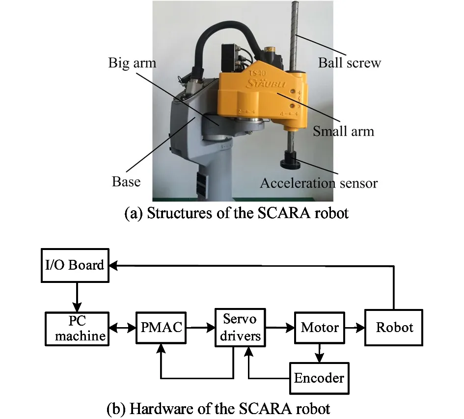
Fig.1 SCARA manipulator
The control system consists of a personal computer (PC), programmable multi-axis controller (PMAC) motion controller, input/output (I/O) board, alternating current (AC) servo motor, and sensors (Fig.1(b)). The PC is designed for man-machine interaction, parameter settings, and inverse kinematics. The PMAC controls the linkage of the servo motor, and the sensor collects various signals in the robot operation and sends them to the PC through the I/O board.
Under this system by using Cartesian coordinate system position control the point-to-point straight line interpolation and continuous interpolation and arc interpolation can be realized. Specific control process is as follows: first, choosing interpolation type via PC, and then according to different type of interpolation the relevant point is calculated, and through the inverse kinematics solution required for each joint rotation angle, the angle will be converted into pulse number via a serial port to be sent to PMAC, PAMC in a specific movement patterns is driven by servo motor to complete the corresponding action.
2 Analysis of the motion signals of robot
2.1 Robot motion data acquisition
The data acquisition function of PMAC is classified into two main approaches, namely, standard and real-time data acquisition through random-access memory (RAM). The obtained robot motion data can be sent directly to the PC or illustrated as motion curves using the Pmac Plot32 Pro in PMAC for further analysis. Fig.2(a) presents the main interface window of the Pmac Plot32 Pro, and its data analysis window is displayed in Fig.2(b). Thus, displacement, speed, and acceleration are determined through data acquisition.
2.2 Acquisition of actual joint-motion data
Fig.3 displays the reference coordinate system of the path planning for a SCARA robot where {O} refers to the absolute coordinate system and {e} is a relative coordinate system. For convenient comparison and analysis, the relative coordinate system is adopted primarily to collect the motion signals of a SCARA robot from point P1(0, 0, 0) to P2(300, 200, -100) at the speeds of 100, 130. In this study, command speed is the rated speed percentage of the robot. The rated speed of each axis is as follows: axis A (Joint 1)is 1.5rad/s, axis B(Joint 2) is 2.0rad/s, axis W(Joint 3) is 3.0rad/s, and axis Z(Joint 4) is 2.4rad/s. The speed of the entire system is controlled by specifying a feed axis during point-to-point movement. If the robot moves from point P1 to point P2, axis Z can act as a feed axis. The command speed of 100 specifies that the operation speed of the robot is ω1=2.4×100%=2.4rad/s. Once the speed of the axis Z is preset, the speeds of the remaining axes can be calculated based on the distance of the corresponding axis and the running time of axis Z. Thus, the four axes arrive at the designated site simultaneously.
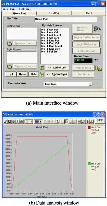
Fig.2 Main interface window of the Pmac Plot32 Pro
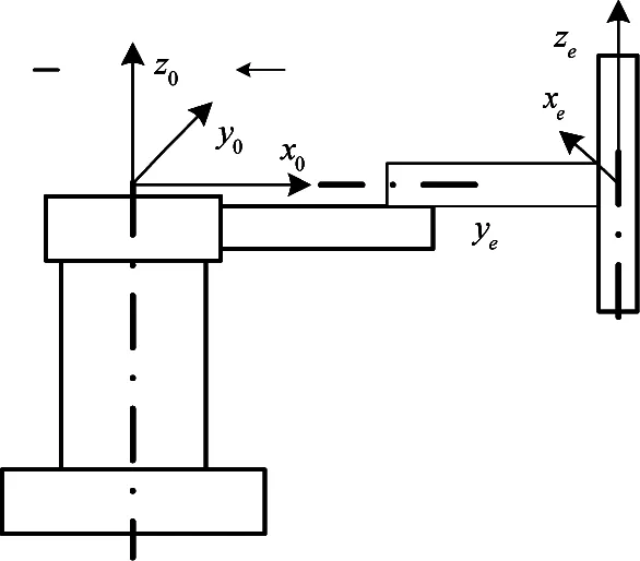
Fig.3 Reference coordinate system of a SCARA robot
Actual robot motion signals can be obtained by directly receiving the feedback of the incremental encoder through PMAC. Fig.4~Fig.7 display the curves of the actual displacements, speeds, and accelerations of Joints 1 and 2.
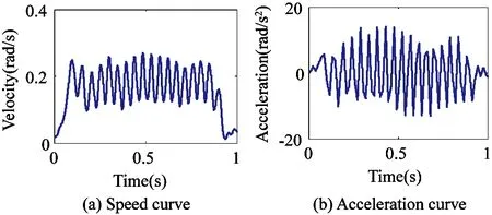
Fig.4 Actual motion curves of Joint 1(ω1=2.4rad/s)
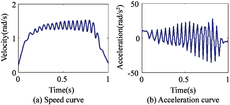
Fig.5 Actual motion curves of Joint 2 (ω1=2.4rad/s)
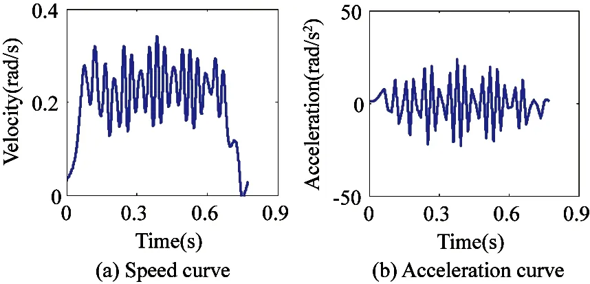
Fig.6 Actual motion curves of Joint 1(ω2=3.12rad/s)
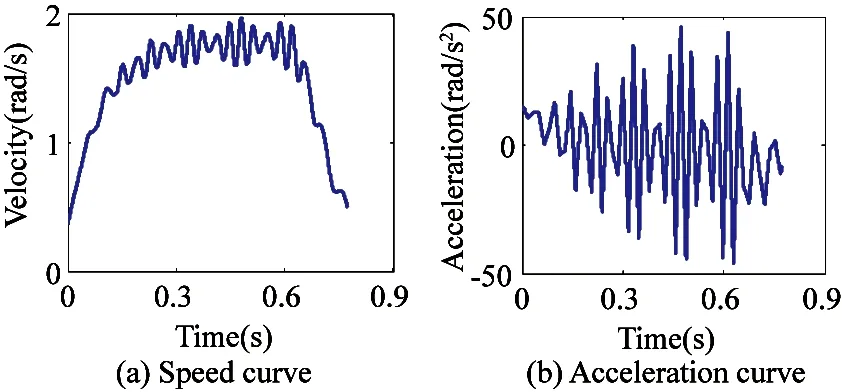
Fig.7 Actual motion curves of Joint 2(ω2=3.12rad/s)
2.3 Analysis of joint vibration
The acceleration curves in Fig.4~Fig.7 are Fourier-transformed to analyze the vibration frequency of joint acceleration at disparate operation speeds. Fig.8 and Fig.9 depict the acceleration spectra of Joints 1 and 2 at operation speeds of v1=2.4rad/s, v2=3.12rad/s. The vibration frequency of Joint 1 basically increases in a fixed ratio with the increase in running speed. As shown in Fig.8(a), (b), Fig.9(a), (b), follow the same law. Moreover, Fig.8 and Fig.9 indicate that the vibration frequencies of Joints 1 and 2 are identical.
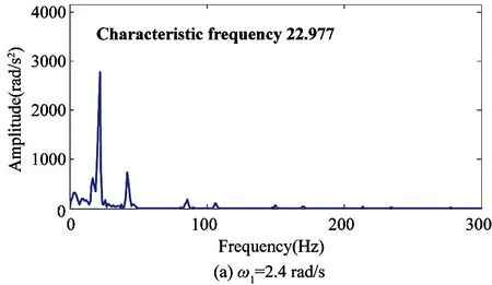
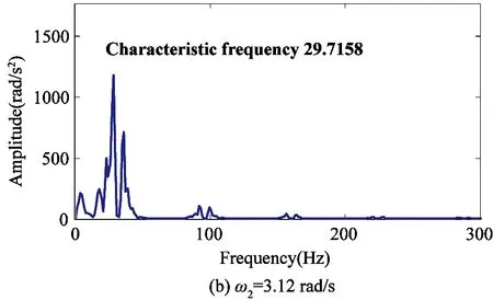
Fig.8 Acceleration spectra of Joint 1
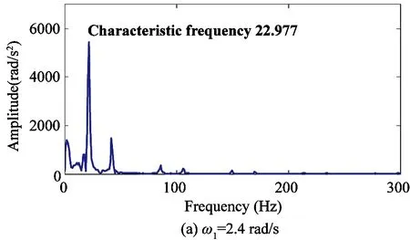
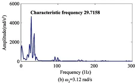
Fig.9 Acceleration spectra of Joint 2
Fig.4~Fig.7 suggest that actual acceleration vibration is mainly induced by speed fluctuation.
3 Analysis of the resultant motion of the end joints of a SCARA robot
3.1 Jacobian matrix
The Jacobian matrix denotes the coefficient matrix used to study the relationship between the speed of the Cartesian space and the torsion angular velocity of each robot joint. The kinematic equation of the SCARA robot is
x=x(q)
(1)
Eq.(1) displays the functional relationship of the spatial coordinate and joint vectors of the SCARA robot. x refers to the six-order vector that describes the position and pose of the end joint and q is a joint vector determined by the degrees of freedom of the robot. By considering the time derivatives on both sides of Eq.(1), Eq.(2) can be obtained:
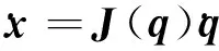
(2)
3.2 Analysis of Jacobian matrix of the SCARA
The Jacobian matrix of the SCARA robot can be solved using the vector product method. Fig.10 shows the coordinate system and joint parameters of the SCARA robot, and Table 1 lists its joint parameters.
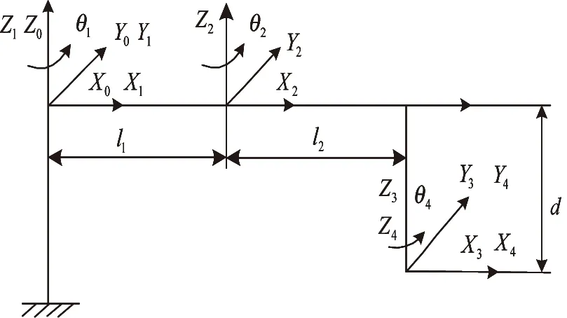
Fig.10 Coordinate system of a SCARA robot
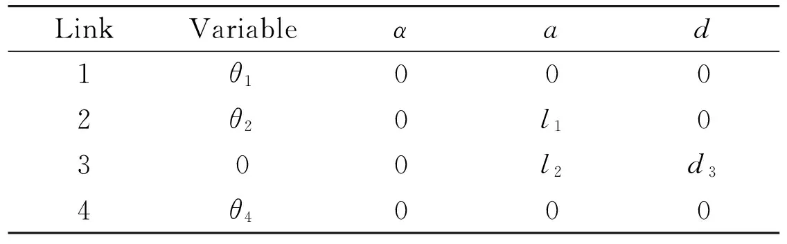
LinkVariableαad1θ10002θ20l10300l2d34θ4000
where l1=0.35m, l2=0.25m
Given that Joints 1, 2, and 4 of the robot are rotational and that Joint 3 is dynamic, the following expression can be generated using the vector product method.
Fig.10 indicates that:

The Jacobian matrix of the SCARA robot is
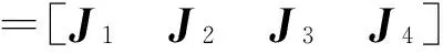
(3)
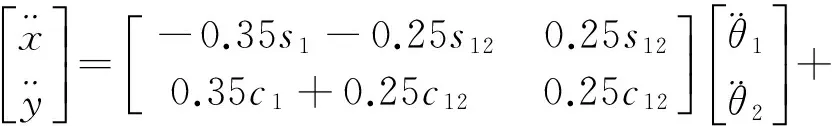
The resultant speed and acceleration of a SCARA robot can be determined using the actual motion displacement, speed, and acceleration of the robot joint. By substituting l1and l1into Eq.(3), the Jacobian matrix J is rewritten as
(4)
By substituting Eq.(4) into Eq.(2), the following is obtained:
(5)
For convenient analysis, this study merely explores the displacement, speed, and acceleration of the end joint of the robot in the x and y directions. Therefore, Eq.(5) is simplified as follows:
(6)
4 Experiments on the resultant motion curve of the end joint of the robot
4.1 Resultant speed curve
Eq.(6) describes the relationship of the speeds in the joint and Cartesian spaces of the robot. It can determine the linear speeds of the robot in the Cartesian space at different operation speeds in the x and y directions. Fig.11 and Fig.12 illustrate the resultant speed curves of the end joints in the x and y directions at operation speeds of ω1=2.4rad/s, ω2=3.12rad/s.
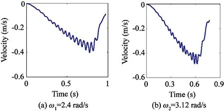
Fig.11 Final resultant speed of the robot in the x direction
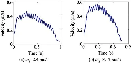
Fig.12 Final resultant speed of the robot in the y direction
4.2 Resultant acceleration curve
Given the time derivate of Eq.(6), the relationships of final acceleration with joint displacement, speed, and acceleration in the Cartesian space can be determined:
(7)
The data regarding the motion of the right joint in Eq.(7) can be attained. Hence, the linear acceleration of the robot in the x and y directions can be identified in the Cartesian space. Fig.13 and Fig.14 display the actual final acceleration curves of the robot in the x and y directions at operation speeds of ω1=2.4rad/s, ω2=3.12rad/s.
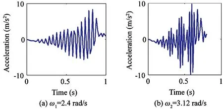
Fig.13 Final resultant acceleration of the robot in the x direction
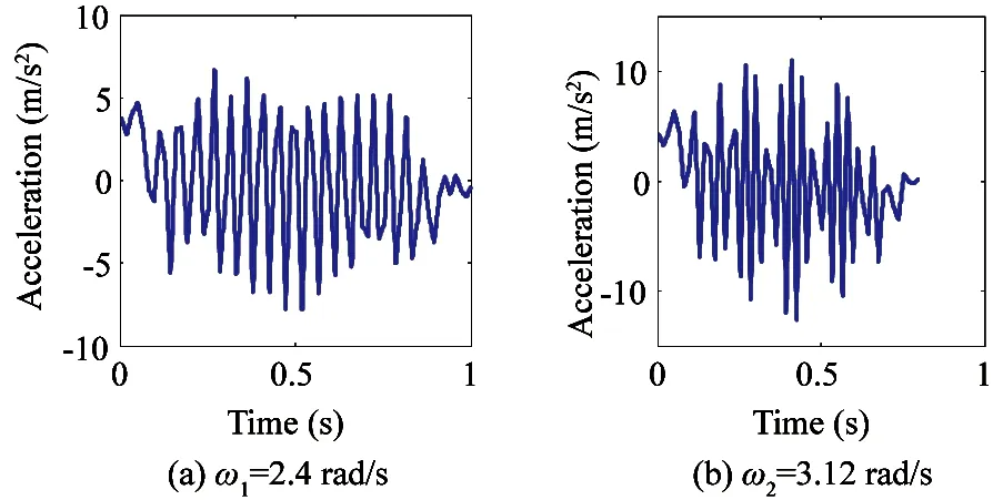
Fig.14 Final resultant acceleration of the robot in the y direction
By Fourier-transforming the resultant acceleration, the corresponding spectra in the x and y directions can be obtained as shown in Fig.15 and Fig.16. The characteristic frequencies of the end joint of the robot are basically identical in the x and y directions at a constant operation speed based on a comparison of both figures. Moreover, the characteristic frequency of the resultant acceleration vibration of the end joint of the robot generally agrees with the acceleration vibration frequencies of joint 1 and joint 2. Thus, the final vibration frequency of the robot remains constant in the x and y directions during operation and increases linearly with operation speed.
5 Conclusion
This study proposes a method to diagnose fault by a single acceleration sensor and designs a synthetic method for the end joints of a SCARA robot in a Cartesian space based on the theory of the Jacobian matrix. The acceleration signals of the end joint of the robot are collected under different operating conditions by simply using an acceleration sensor installed at the end. By comparing the characteristic frequency of acceleration of joint 1 and joint 2 with synthetic acceleration to illustrate the accuracy of the method. The acceleration vibration signals of robot joints during actual operation are analyzed, and the characteristic frequency of joint acceleration signals is linearly related to a specified speed. Accordingly, the speed and acceleration of the end joint of the robot are deduced in the x, y directions in the Cartesian space. By comparing the results of frequency spectrum analysis on the final acceleration signals and normal running state of robot, the real operation status can be determined.
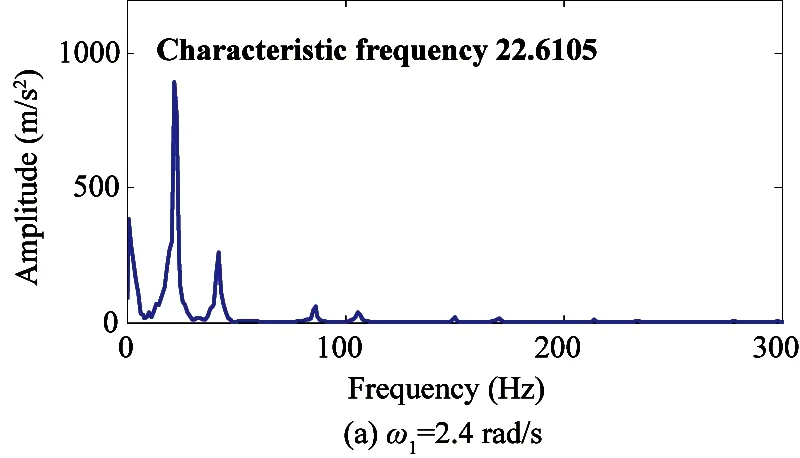
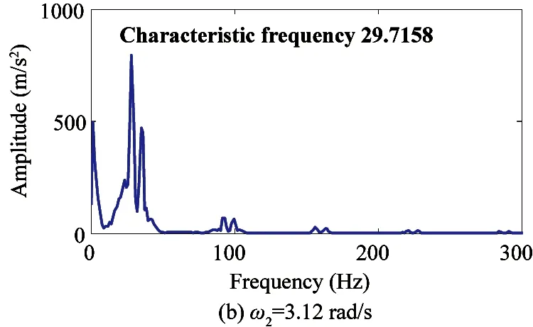
Fig.15 Resultant acceleration spectra of the end joint of the robot in the x direction
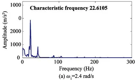

Fig.16 Resultant acceleration spectra of the end joint of the robot in the y direction
Reference
[ 1] Shin J H, Lee J J. Fault detection and robust fault recovery control for robot manipulators with actuator failures. In: Proceedings of the IEEE International Conference on Robotics and Automation, Detroit, USA, 1999. 861-866
[ 2] Ting Y, Tosunoglu S, Tesar D. A control structure for fault tolerant operation of robotic manipulators. In: Proceedings of the IEEE International Conference on Robotics and Automation, Atlanta, USA, 1993. 684-690
[ 3] Wu E C, Hwang J C, Chladek J T. Fault tolerant joint development for the space shuttle remote manipulator system: Analysis and development. IEEE Transactions on Robotics and Automation, 1993, 9(5): 675-684
[ 4] Zanaty F. Consistency checking techniques for the space shuttle remote manipulator system. SPAR Journal of Engineering Technology, 1993, 2(1): 40-49
[ 5] Visinsky M L, Cavallaro J R, Walker I D. Dynamic sensor-based fault detection for robots. In: Proceedings of the 1993 SPIE Conference on Telemanipulator Technology and Space Robotics,Boston, USA, 1993. 385-396
[ 6] Wu B Y, Yan Q Q, Luo J F, et al. Signal processing and application of six-axis force/torque sensor integrated in humanoid robot foot. Journal of Signal Processing Systems for Signal Image and Video Technology, 2014, 74(2): 263-271
[ 7] Cheein F A A, Sciascio F, Carelli R, et al. Probabilistic workspace scan modes of a robot manipulator commanded by EEG signals. In: Proceedings of the 1st International Conference on Biomedical Electronics and Devices, Funchal, Portugal, 2008, 2:3-8
[ 8] Liu Y T, Chen J A. Integrated fault diagnosis method of mobile robot. In: Proceedings of the 2nd International Conference on Theoretical and Mathematical Foundations of Computer Science (ICTMF 2011), Singapore, 2011,164: 372-379
[ 9] Hoang N B, Kang H J. A model-based fault diagnosis scheme for wheeled mobile robots. International Journal of Control Automation and Systems, 2014, 12(3): 637-651
[10] Ferreira A, Bastos T F, Sarcinelli M, et al. Teleoperation of an industrial manipulator through a TCP/IP channel using EEG signals. In: Proceedings of the IEEE International Symposium on Industrial Electronics, Montreal, Canada, 2006. 3066-3071
[11] Fourlas G K. Theoretical approach of model based fault diagnosis for a 4-wheel skid steering mobile robot. In: Proceeding of the 21st Mediterranean Conference on Control and Automation, Platanias, Greece, 2013. 597-602
[12] Gao Z W, Liu X X, Chen Michael Z Q. Unknown input observer-based robust fault estimation for systems corrupted by partially decoupled disturbances. IEEE Transactions on Industrial Electronics, 2016, 63(4): 2537-2547
[13] Stavrou D, Eliades D G. Fault detection for service mobile robots using model-based method. Autonomous Robots, 2016,40(2): 383-394
[14] Zhao B, Li C H, Liu D R. Decentralized sliding mode observer based dual closed-loop fault tolerant control for reconfigurable manipulator against actuator failure. PLOS One, 2015, 10(7): e0129315
[15] Zhang J, Swain A K, Nguang S K. Robust sliding mode observer based fault estimation for certain class of uncertain nonlinear systems. Asian Journal of Control, 2015,17(4):1296-1309
[16] She Y, Xu W F, Su H J. Fault-tolerant analysis and control of SSRMS-type manipulators with single-joint failure. Acta Astronautica, 2016,120:270-286
the Ph.D. degree from Southeast University in 2009 and his M.S. degree from Hefei University of Technology in 2005. He was an associate professor of the Automation Engineering of Nanjing University of Posts and Telecommunications. His current research interests include robotics and dynamics.
10.3772/j.issn.1006-6748.2017.03.008
Supported by the National Natural Science Foundation of China (No. 51775284), Natural Science Foundation of Jiangsu Province(BK20151505), and Joint Research Fund for Overseas Chinese, Hong Kong and Macao Young Scholars (61728302).
To whom correspondence should be addressed. E-mail: xufengyu598@163.com
on May 6, 2016
杂志排行

High Technology Letters的其它文章
- Quantitative analysis of the performance of vector tracking algorithms①
- Application of linear active disturbance rejection control for photoelectric tracking system①
- Structure design of gradient hard coatings on YG8 and their residual stress analysis by ANSYS①
- ZnO whiskers growth on the surface of Sn9Zn/Cu solder joints in concentrator silicon solar cells solder layer①
- Characterizing big data analytics workloads on POWER8 SMT processors①
- A leveling mechanism for the platform based on booms-constraint control of aerial vehicle①