Ground demonstration system based on in-orbit assembly oriented manipulator flexible force control①
2017-09-25QiaoGuanyu乔冠宇GaoHuibinPengChengGuYingyingXuZhenbangXuBoqian
Qiao Guanyu (乔冠宇), Gao Huibin, Peng Cheng, Gu Yingying, Xu Zhenbang, Xu Boqian
(*Innovation Laboratory of Space Robot System,Space Robot Engineering Center, Changchun Institute of Optics, Fine Mechanics and Physics, Chinese Academy of Sciences, Changchun 130033, P.R.China)(**University of Chinese Academy of Sciences, Beijing 100039, P.R.China)
Ground demonstration system based on in-orbit assembly oriented manipulator flexible force control①
Qiao Guanyu (乔冠宇)***, Gao Huibin*, Peng Cheng②*, Gu Yingying*, Xu Zhenbang*, Xu Boqian*
(*Innovation Laboratory of Space Robot System,Space Robot Engineering Center, Changchun Institute of Optics, Fine Mechanics and Physics, Chinese Academy of Sciences, Changchun 130033, P.R.China)(**University of Chinese Academy of Sciences, Beijing 100039, P.R.China)
To eliminate the load weight limit of carrier rockets and reduce the burden on support structures,in-orbit assembly is a key technology to make design of scattering a large diameter telescope into submirror modules, which requires smooth operation of assembly robots, and flexible force control technology is necessary. A ground demonstration system is presented for in-orbit assembly focusing on flexible force control. A six-dimensional force/torque sensor and its data acquisition system are used to compensate for gravity. For translation and rotation, an algorithm for flexible control is proposed. A ground transportation demonstration verifies accuracy and smoothness of flexible force control, and the transportation and assembly task is completed automatically. The proposed system is suitable for the development of in-orbit assembly robots.
flexible force control, gravity compensation, ground demonstration system, in-orbit assembly, manipulator, six-dimensional force/torque sensor
0 Introduction
Technological progress and curiosity drive humans to explore the unknown universe. To make better observations of the universe, higher calibre optical systems are required. However, increasing dimensions of optical systems present new challenges. For example, with greater mass and volume, the demand on the support structure increases, pushing the load weight limit of the carrier rocket. For further improvements to space-based optical systems, a new approach utilizing in-orbit assembly and manufacturing is required. For such tasks, flexible manipulator makes ideal workers. To ensure manipulators to finish tasks safely and smoothly, measurement and flexible force control are most important. The six-dimensional (6D) force/torque sensor plays an important role in the flexible force control of manipulator[1,2]. A most widely used principle of measuring the forces and torques is based on strain gauges. Many kinds of 6D force/torque sensors developed depend on strain gauges with different structures such as cross beam designed by Chao and Chen[3], Wu, et al.[4], the form of four identical T-shaped bars designed by Liu and Tzo[5].
On the other hand,the classification of force control is indirect force control and hybrid force and motion control. Several methods of manipulator force control have been proposed in different gravity environments, such as active disturbance rejection control (ADRC)[8], robust adaptive control (RAC)[9]and adaptive inversion sliding mode control (AISMC)[10]. The reliability and convenience of implementation of such methods are key for operation in space.Therefore it is necessary to design a simple and feasible method in view of the in-orbit assembly.
1 System composition and working process
Designs for a ground demonstration system based on an industrial robot arm for use in in-orbit assembly are presented. The proposed system includes an industrial robot arm, a 6D force/torque sensor and its data acquisition hardware and software system, two binocular stereo vision systems, a robot end effector and a turntable for transportation and placing of the submirrors. The system composition is shown in Fig.1 and Fig.2.
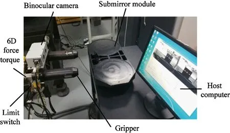
Fig.1 Robot end effector composition
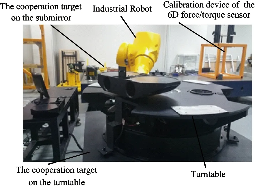
Fig.2 Turntable composition
Three submirror modules with steel structures are designed. There are cooperation targets on each submirror to aid the positioning camera. The robot end effector is designed to have two cylindrical structures inserted into the corresponding round holes in the submirrors to allow transportation. The 6D force/torque sensor is attached between the manipulator and its end effector. Two binocular stereo vision systems are enclosed in two small boxes and fixed above and below the end effector. The end effector also features a travel switch to determine whether it is mated correctly to the submirror.
The working process of the whole system is shown in Fig.3.
First, the manipulator moves into the visual field of the top camera by path planning and sends command to the vision system. The Cartesian position of path and adjustment is shown in Fig.4. The vision system then begins to calculate the position and attitude of the end effector and sends the data to the manipulator controller in real time. The manipulator moves quickly to the expected position and attitude. When the distance between the end effector and the submirror module is very close, the force feedback system takes over from the vision system. The end effector is inserted into the submirror module smoothly according to the compliance control algorithm using force and torque data collected in real time. Following the same principle as the insert process, when the manipulator carrying the submirror is moving to the expected position, the bottom camera is used. When the manipulator is lowering and placing the submirror, the force feedback system is taken over again, which completes the transportation and assembly of the first submirror. The platform locks the submirror and rotates 120 degrees, then waits for the command to fetch the next submirror. Attaching the second and third submirrors follows the same process as the first.
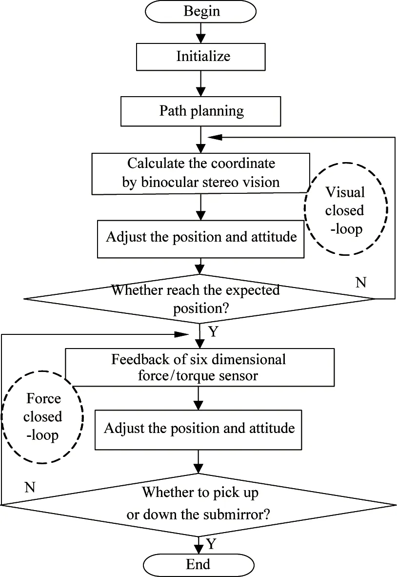
Fig.3 Working process of the force control system
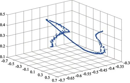
Fig.4 Cartesian position of path plan and adjustment
2 Design of the 6D force/torque sensor
2.1 Design of the 6D force/torque sensor
Performance of the 6D force/torque sensor is primarily influenced by the elastomer design. The structure and design of the elastomer directly affect factors including sensitivity of the sensor, difficulty and accuracy of the paster, coupling between each dimensional force and clarity of the sensor benchmark coordinates. In the present study, an elastomer is designed as a cross-beam symmetric structure, as shown in Fig.5. The design specifications of the 6D force/torque sensor are shown in Table 1.
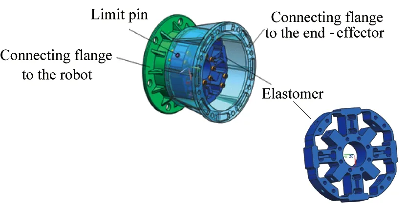
Fig.5 Structure and installation of the six-dimensional force/torque sensor
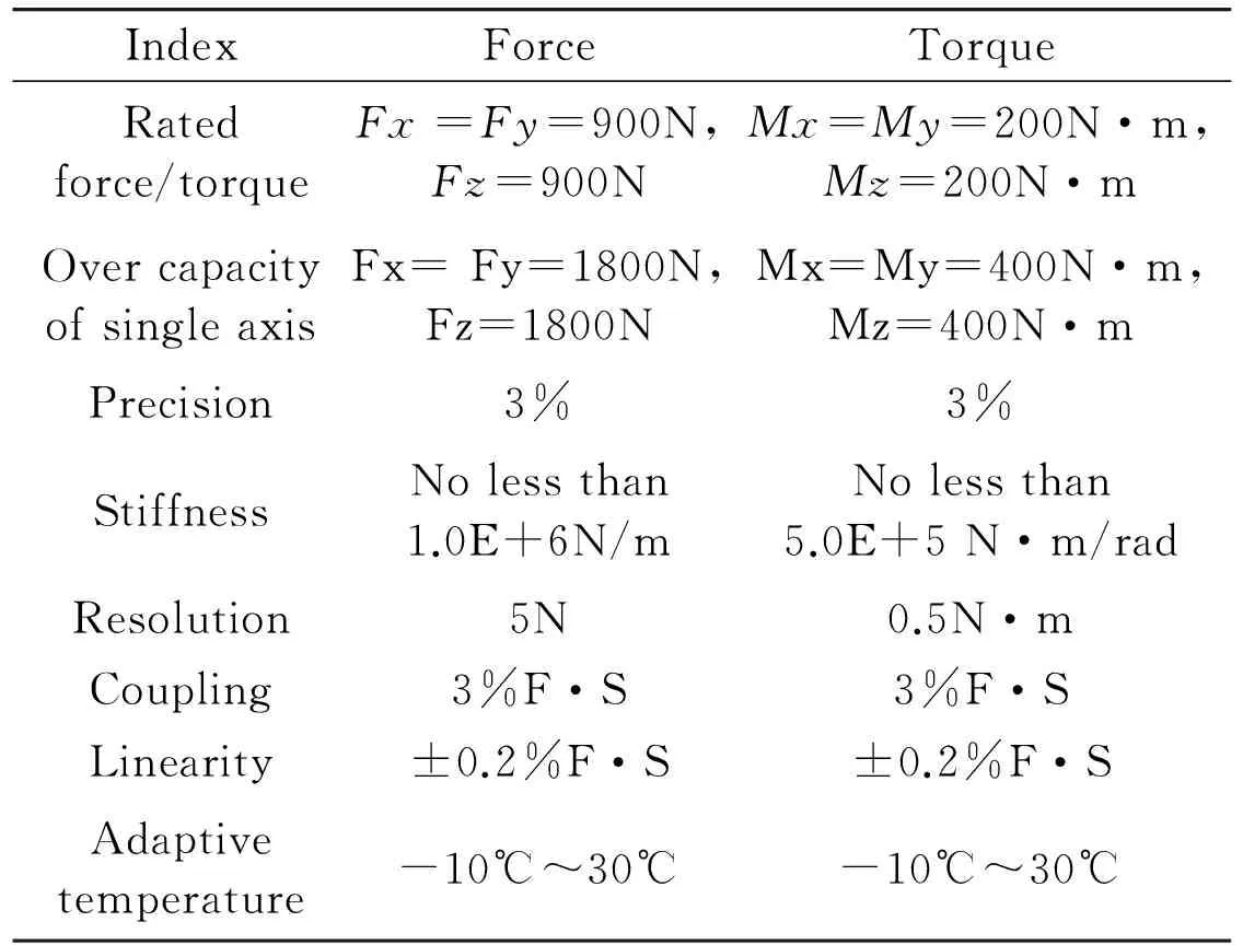
IndexForceTorqueRatedforce/torqueFx=Fy=900N,Fz=900NMx=My=200N·m,Mz=200N·mOvercapacityofsingleaxisFx=Fy=1800N,Fz=1800NMx=My=400N·m,Mz=400N·mPrecision3%3%StiffnessNolessthan1.0E+6N/mNolessthan5.0E+5N·m/radResolution5N0.5N·mCoupling3%F·S3%F·SLinearity±0.2%F·S±0.2%F·SAdaptivetemperature-10℃~30℃-10℃~30℃
The data acquisition system of 6D force/torque sensor is shown in Fig.6. The 6D force/torque sensor converts the resistance of the strain gauge into a voltage signal by the bridge module. This weak signal is amplified by the amplifier module. The phase-sensitive detector module restores the enlarged amplitude modulation to measured strain signal waveform and, at the same time, reflects the direction of the measured strain signals. The filter module filters the high-order harmonic component of the output signal to achieve the desired output waveform. The oscillator module produces a stable oscillation voltage for the reference voltage of the phase-sensitive detector and bridge power supply voltage. Finally the 485 communication module transmits the six output waveforms to the host computer. The power supply module provides a stable +5V power supply to the acquisition circuit.
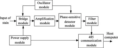
Fig.6 Flow diagram of data acquisition system of the six-dimensional force/torque sensor
2.2 Gravity compensation
The 6D force/torque sensor is fixed between the manipulator and its end effector as shown in Fig.1. Gravity has a strong influence on the 6D force/torque sensor. To acquire information about whether the load is being affected by external forces such as collisions, it is necessary to compensate for the influence of gravity. If there is no other external force on the load, the force and torque information measured by the 6D sensor are completely caused by gravity acting on the load. To calibrate the sensor, the manipulator and end effector are moved in different attitudes to collect measurement data from the 6D sensor. Least squares regression is then used to estimate the mass of the load size and the center of gravity coordinate.
The rectangular coordinate system for the 6D force/torque sensor under gravity is shown in Fig.7. X, Y and Z are the three coordinate axes. The gravity of the load is G, the coordinate of the center of mass of
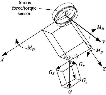
Fig.7 Effect of gravity on the coordinate system of the 6D force/torque sensor
the 6D force/torque sensor is (x, y, z). The force components of G in the X, Y and Z directions are Gx, Gyand Gz, respectively. The torque components of G around X, Y and Z axes are Mgx, Mgyand Mgz, respectively. According to the relationship between force and torque, Eq. (1) can be got:
(1)
The center of mass of the load (x, y, z) and the gravity of the load can easily be found using a number of different load attitude groups of 6D force sensor measurement data.
Assuming there are external forces acting on the load, the 6D force/torque sensor three measured force components are Fx, Fyand Fz, and the three measured torque components are Mx, Myand Mz. The direction of the gravitational forces changes depending on the attitude of the end effector. After calibration of the manipulator attitude, angles α, β and γ between the gravity direction and the 6D force/torque sensor coordinate system X, Y and Z can easily be obtained. Then the gravity components in the 6D sensor coordinate system can be calculated:
(2)
In Eq.(2), Gx, Gyand Gzare components of Fx, Fyand Fzthat the 6D force/torque sensor are measured due to the gravity. Substituting Eq.(2) and the load barycentric coordinates (x, y, z) into Eq.(1), Mgx, Mgyand Mgzthe torque components of Mx, Myand Mzthat the 6D sensor measured due to the gravity are given.
The external forces on the three-axis components are
(3)
The external torques on the three-axis components are
(4)
3 Flexible force control algorithm
First, external forces/torques are detected in real time by deformation of the elastomer, where they are decoupled into forces (Fx, Fyand Fz) and torques (Mx, Myand Mz) by the data acquisition and processing systems. According to the force and torque information, the controller plans flexible servo motions to complete the particular task smoothly. The flexible force control process is shown in Fig.8.
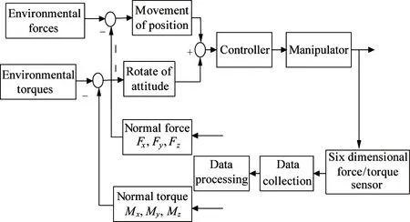
Fig.8 Flow diagram of flexible force control
For controlling movement velocity, the external force is taken as a system input. The external forces measured by the system are nonzero, even when there are no external forces, due to sensor errors and gravity compensation. Therefore, only if measured force F is greater than some threshold Fsdoes it affect the movement velocity. The relationship between movement velocity V and measured external force F is shown in Fig.9. When F is greater than Fsand smaller than Fs2, V increases linearly with increasing F. When F is equal to or greater than Fs2, V is a maximum Vmax. The value of V with F continuousty changes without jump under the relationship of V-F to avoid flog because of the change of external forces. When F is greater than Fsand smaller than Fs2, it is in line with people’s daily habits that the greater the external force, the faster the movement. Vmaxis set for safe operation. Total velocity V is determined and separated into velocity components (Vx, Vyand Vz) according to each force component (Fex, Feyand Fez), which ensures the direction of the movement and the external force are the same and allows flexible servo motion.
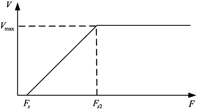
Fig.9 Relationship of V-F
The flow diagram of the movement control algorithm is shown in Fig.10.
For controlling rotation, rotation speed is associated with the external torques about X, Y and Z axes. The flow diagram of the rotation control algorithm is shown in Fig.11.
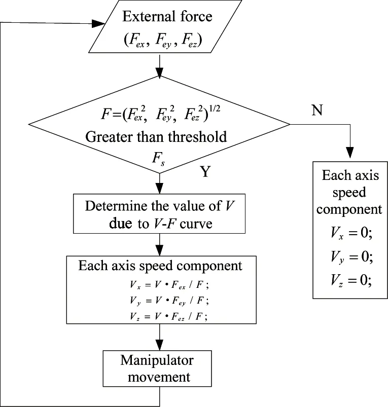
Fig.10 Flow diagram of movement control
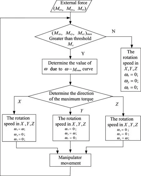
Fig.11 Flow diagram of rotation control
First it is compared with the torques about the X, Y and Z axes (Mex, Mey, and Mez) and threshold Msis set for maximum external torque Memaxin the same way. Only if it is greater than Msdoes the external torque affect the rotation. The relationship between rotation speed ω and value of external torque Memaxis shown in Fig.12.
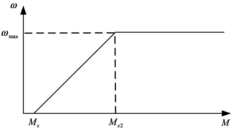
Fig.12 Relationship of ω-Memax
4 Realization of flexible force control
For the ground demonstration system, a TX200 manipulator (Staubli, Sweden) is used for flexible force control. The main specifications of the manipulator are shown in Table 2.
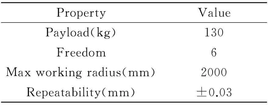
Table 2 Specifications of the robot arm
The 6D force/torque sensor is connected between the end of the sixth joint of manipulator and the end effector using a flange. Three groups of force/torque data are collected by the data collection system per second. The weight of the end effector is 25kg. The weight of the whole system including the end effector and submirror module is 40kg. The movement speed is limited to 80mm/s and the rotation speed is limited to 90°/s. The external force threshold is set at 10N and the external torque threshold is set at 5Nm. Results shows that the design and control process realizes the flexible force control during the transportation task. The motion is smooth without jitter. Fig.13~Fig.18 show the angle of joint 1~joint 6 under the control algorithm during entire experiment.
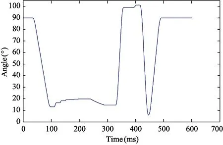
Fig.13 The angle of joint 1 during experiment
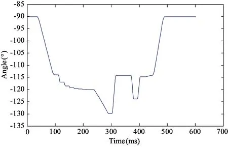
Fig.14 The angle of joint 2 during experiment
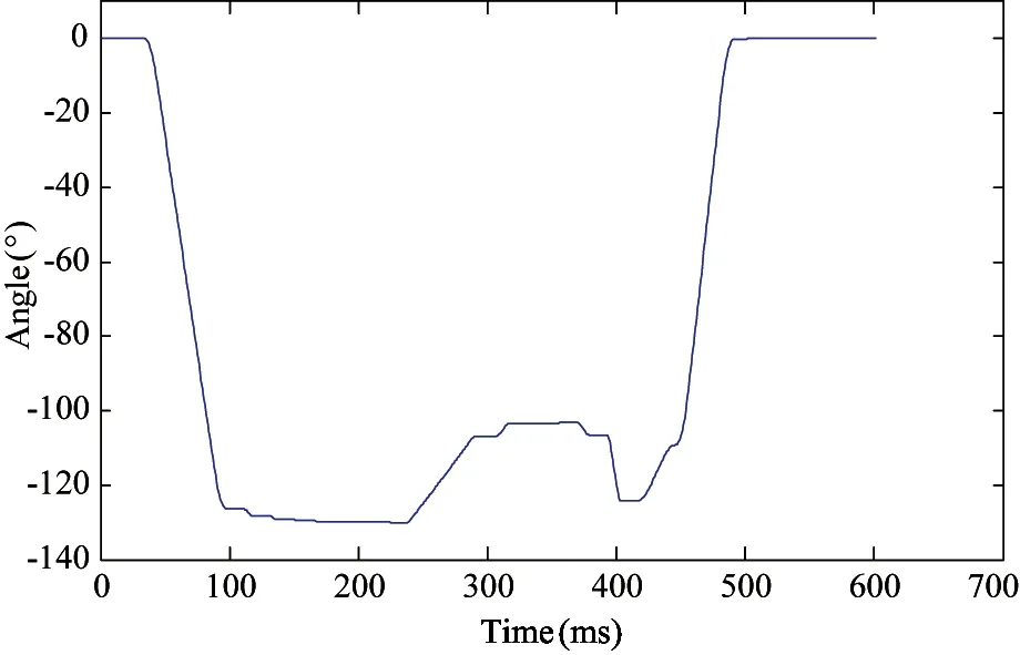
Fig.15 The angle of joint 3 during experiment
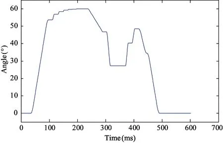
Fig.16 The angle of joint 4 during experiment
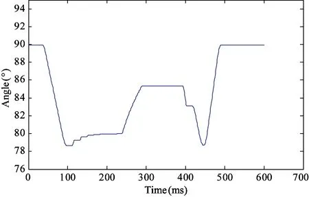
Fig.17 The angle of joint 5 during experiment
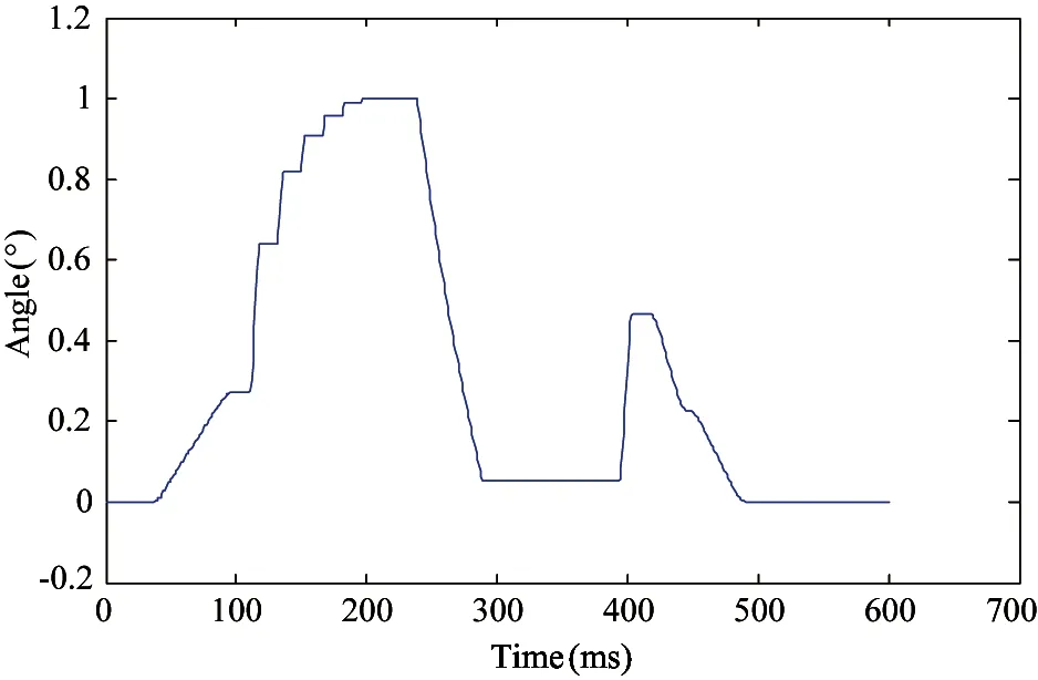
Fig.18 The angle of joint 6 during experiment
Fig.19, Fig.21 ang Fig.23 show the force waveform and Fig.25, Fig.27 and Fig.29 show the torque waveform in the process of the whole work. An experiment under the condition without gravity compensation is done. Fig.20, Fig.22, Fig.24, Fig.26, Fig.28, Fig.30 show the force and torque without gravity compensation.The motion is full of jitter so it does not accomplish the submirror module transportation and assembly.
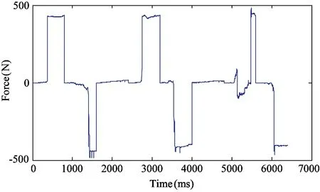
Fig.19 Force in the direction of the X axis
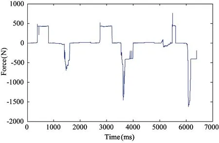
Fig.20 Force without gravity compensation in the direction of the X axis
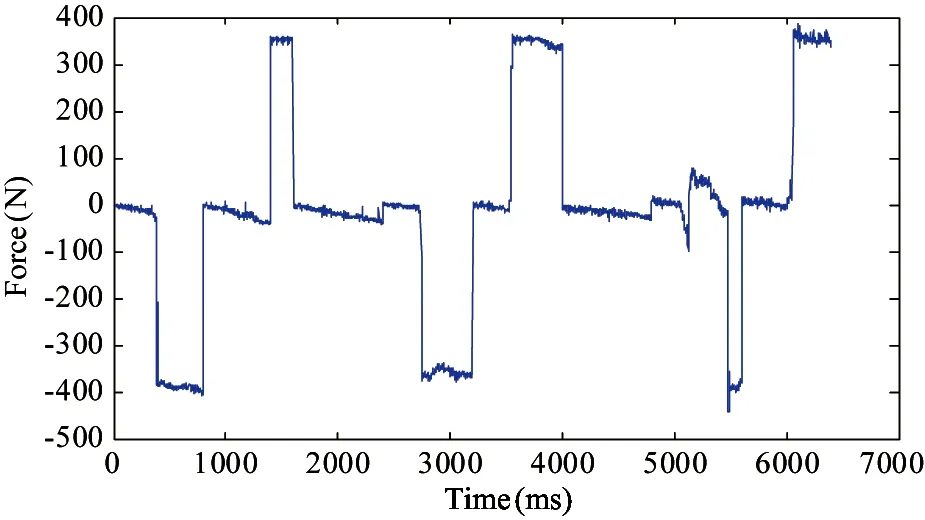
Fig.21 Force in the direction of the Y axis
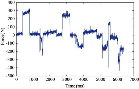
Fig.22 Force without gravity compensation in the direction of the Y axis
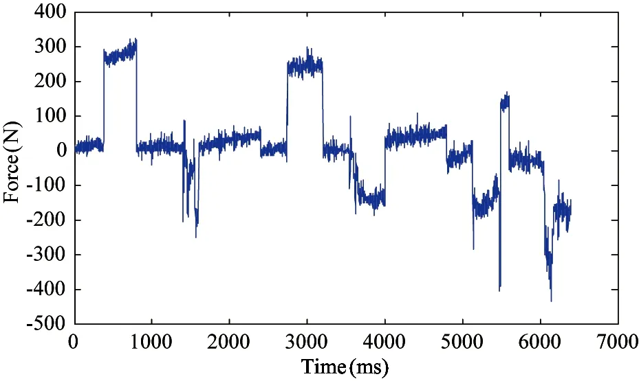
Fig.23 Force in the direction of the Z axis
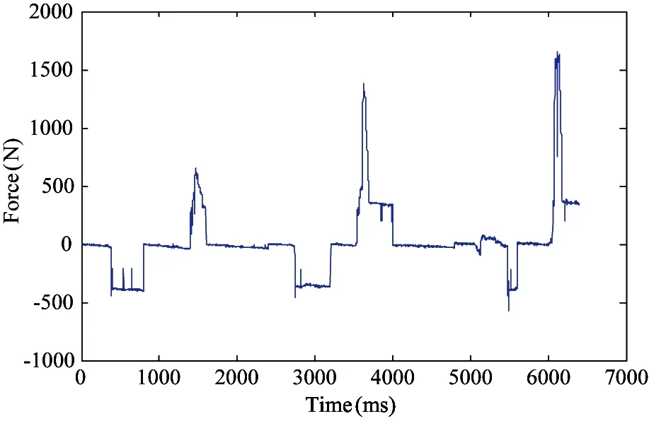
Fig.24 Force without gravity compensation in the direction of the Z axis
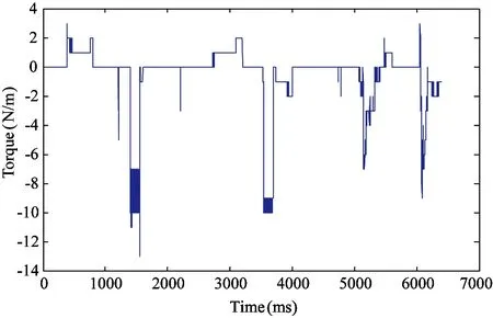
Fig.25 Torque about the X axis
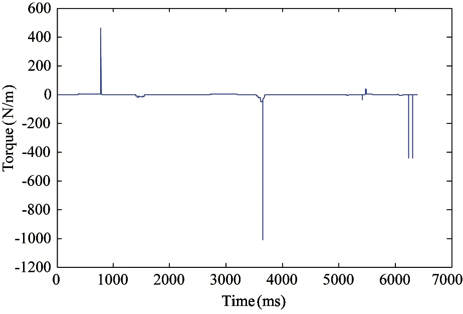
Fig.26 Torque without gravity compensation about the X axis
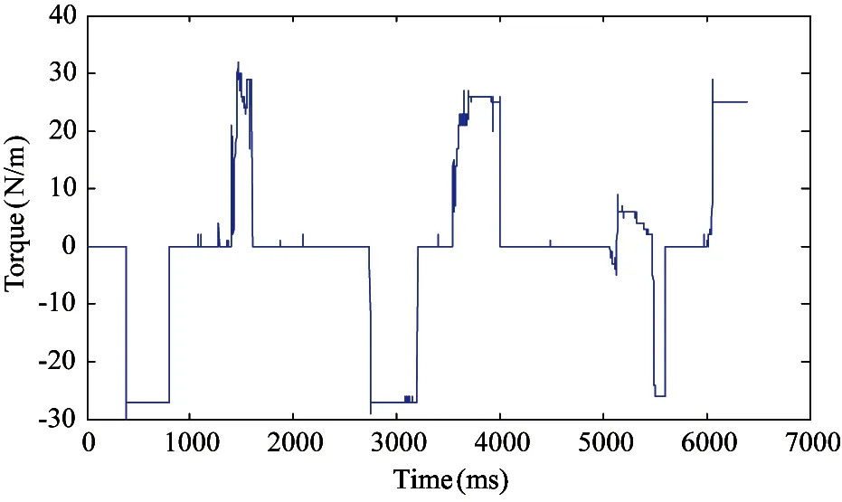
Fig.27 Torque about the Y axis
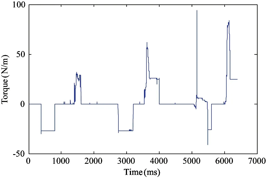
Fig.28 Torque without gravity compensation about the Y axis
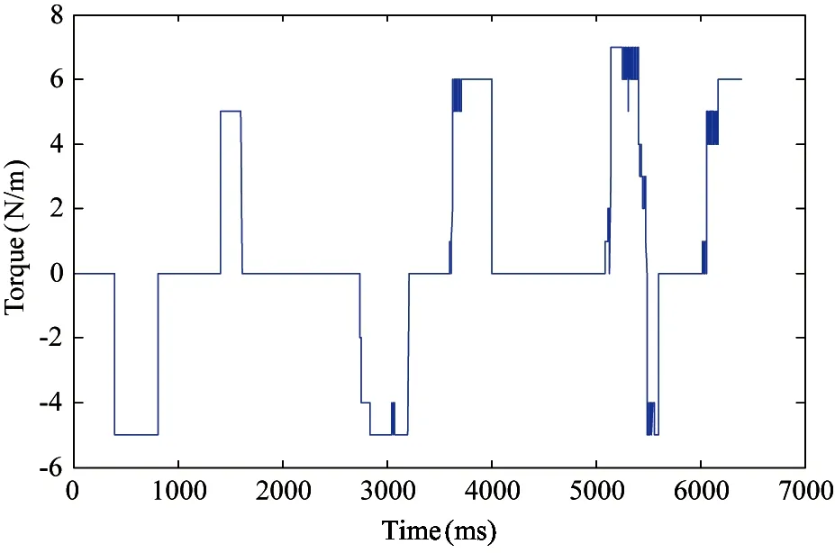
Fig.29 Torque about the Z axis
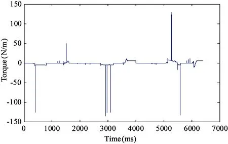
Fig.30 Torque without gravity compensation about the Z axis
5 Conclusion
A ground demonstration system for in-orbit assembly is proposed and tested. Flexible force control during the transportation task using a 6D force/torque sensor is realized. For the process of the end effector inserted the submirror module and carried the submirror to the specified location, V-F and ω-Memaxrelationships are designed to control the movement and rotation of the end effector. Results verify that the proposed processes are suitable for in-orbit transportation and assembly.
[ 1] Laryssa P, Lindsay E, Layi O, et al. International space station robotics: a comparative study of ERA, JEMRMS and MSS. In: Proceedings of the 7th ESA Workshop on Advanced Space Technologies for Robotics and Automation ASTRA, Noordwijk, Netherlands, 2002. 19-21
[ 2] Boumans R, Heemskerk C. The European robotic arm for the international spaces tation. Robotics and Autonomous Systems, 1998, 23(1-2):17-27
[ 3] Chao L P, Chen K T. Shape optimal design and force sensitivity evaluation of six-axis force sensors. Sensors and Actuators A: Physical, 1997,63(2):105-112
[ 4] Wu B, Luo J, Shen F, et al. Optimum desigh method of multi-axis force sensor integrated in humanoid robot foot system. Measurement, 2011,44(9):1651-1660
[ 5] Liu S A, Tzo H L. A novel six-component force sensor of good measurement isotropy and sensitivities. Sensors and Actuators A: Physical, 2002,100(2-3): 223-230
[ 6] Stramigioli S. Modeling and IPC Control of Interactive Mechanical Systems—A Coordinate Free Approach. Springer, London: Lecture Notes in Control and Information Sciences, 2001, 266(1): 169-170
[ 7] DeSchutter J, DeLaet T, Rutgeerts J, et al. Constraint-based task specification and estimation for sensor-based robot systems in the presence of geometric uncertainty. International Journal of Robotics Research, 2007,26(5):433-455
[ 8] Liu F C, Hou T T, Jia X J. Space manipulator modeling and control considering the effect of clearance hinge and gravity. Chinese High Technology Letters, 2015,25(6):599-606(In Chinese)
[ 9] Liu F C, Gao J F, Li Q. Adaptive Robust Control of flexible space manipulator in different gravity environment. Chinese High Technology Letters, 2015, 25(1): 61-69(In Chinese)
[10] Liu F C, Li Q, Liang L H, et al. Adaptive Inverse Control of flexible space manipulator trajectory tracking in different gravity environment. Chinese High Technology Letters, 2015, 25(4): 384-392(In Chinese)
Qiao Guanyu, born in 1987. He is a Ph.D candidate in Changchun Institute of Optics, Fine Mechanics and Physics, Chinese Academy of Sciences. He received his M.S. degree in Machinery and Electronics Engineering of University of Chinese Academy of Sciences in 2013. He also received his B.S. degree from Jilin University in 2010. His research interests include the modeling and control of robots, robot force contrlo.
10.3772/j.issn.1006-6748.2017.03.007
Supported by the National Natural Science Foundation of China (No. 11672290).
To whom correspondence should be addressed. E-mail: qgy008@163.com
on Mar. 9, 2017
杂志排行

High Technology Letters的其它文章
- Quantitative analysis of the performance of vector tracking algorithms①
- Application of linear active disturbance rejection control for photoelectric tracking system①
- Structure design of gradient hard coatings on YG8 and their residual stress analysis by ANSYS①
- ZnO whiskers growth on the surface of Sn9Zn/Cu solder joints in concentrator silicon solar cells solder layer①
- Characterizing big data analytics workloads on POWER8 SMT processors①
- A leveling mechanism for the platform based on booms-constraint control of aerial vehicle①