基于混合方法的轨道交通牵引电机离心风扇的气动及噪声性能计算
2017-09-16申政王彤
申 政 王 彤
(1.中车株洲电机有限公司;2.上海交通大学机械与动力工程学院)
基于混合方法的轨道交通牵引电机离心风扇的气动及噪声性能计算
申 政1王 彤2
(1.中车株洲电机有限公司;2.上海交通大学机械与动力工程学院)
作为轨道车辆的主要动力来源,牵引电机在高转速下会产生很大的气动噪声。为改进电机的气动性能并降低气动噪声,本文采用基于CFD仿真与声比拟的混合方法计算某牵引电机内部流场及气流产生的噪声,取得三个转速下的气动性能。同时,本文对电机内部流场及气动噪声来源进行了分析和展示。最后,本文提出了对风扇和流道设计的改进措施,以提升流动效率和降低气动噪声。
混合方法;计算流体动力学;声比拟;气动性能;气动噪声
0 Introduction
Railroad transportation is witnessing rapid development in China and other developing countries. Various sectors,including high-speed railway,urban rail transit,and traditional locomotives,are playing increasingly important roles in the economic development[1].
Along with the growing operational speeds of trains,aeroacoustic noise builds up[2].Long lasting and high intensity noise can lead to serious aural damage and produce stress in humans[3].Hence,various noise reduction techniques,such as streamlined design[4],sound absorbing and insulation materials[5], are being investigated and implemented on urban transportation and high-speed trains by major railroad vehicle manufacturers.
Railroad Traction Motors(TM)[6]are the main traction power provider to the trains,which convert electric power into traction force and produce motion.For the trains to run in different directions,TMs are designed to allow both forward and reversal rotations and maintain similar electric and mechanical characteristics for both rotational directions.Hence,the straight blade type is always used in centrifugal fan,i.e.,the blade angle between the inlet and outlet is 90 degree.Compared with conventional fans,it results in relatively poor aerodynamic performance and strong aeroacoustic noise.For many TMs,the centrifugal fan is installed on the rotor,making it difficult to test the performance of the fan.It is only possible to measure the relationship between the aerodynamic resistance and the air flow rate in the TM.Now the CFD method can be used to simulate the flow characteristics inside the impeller and analyze the source of the aeroacoustic noise.In railroad transit,the TM is one of the main noise contributors,which generates sharp electromagnetic noise[7]and broad band aeroacoustic noise[8].
Empirically,at high rotating speeds(>4 000rpm),aeroacoustic noise induced by airflow accounts for over 80%of the total noise power of a TM[2].Therefore,research on motor ventilation design,internal flow field,and aeroacoustic noise source is crucial for noise control at high rotating speed.
Computational Fluid Dynamics(CFD)[9-10]is a powerful numerical simulation tool for flow field,heat transfer,and flow-induced noise research[11].From CFD results,we are able to find where airflow is blocked and turbulence occurs,which assists us to redesign the flow paths,improve flow efficiency,and hence reduce aeroacoustic noise.
Nevertheless,CFD is often computationally difficult and time-consuming,restricting its use in industries like railroad TM with very tight schedules for products delivery. To efficiently investigate the flow field and noise source,approximations and simplifications must be introduced to the CFD model and algorithm.
This paper presents a hybrid method based on CFD simulation and acoustic analogy for studying aerodynamic performance and aeroacoustic noise of TMs.Performance curves at various rotational speeds are obtained for a TM used in urban rail transit.The internal flow field and major aeroacoustic noise source of the TM are analyzed and visualized.The aeroacoustic noise is revealed.Guidelines formodification are also provided to improve flow efficiency and reduce noise.
1 Methodology and CFD model development
A TM used in urban rail transit is illustrated in Figure 1.Air flows into the inlet and passes through small vents inside the rotor and stator,which takes away heat generated by the TM.A centrifugal fan is mounted on the motor shaft near the outlet and rotates at the same speed as the shaft,which impels the heated airflow out of the motor.
Aeroacoustic noise of the TM comes primarily from the fan impeller(the centrifugal fan and motor case,Fig.1(b)).So we focus on the impeller instead of the entire motor to reduce computational cost.
A 3D model of the interested fluid domain(enclosureof the impeller)is prepared for CFD simulation of the blower,as shown in Fig.2 and Fig.3.

Fig.1 An urban rail transit traction motor model

Fig.2 Fluid domain with flow directions(arrows)
Fig.2 provides an overview of the entire fluid domain which consists of 3 parts:‘inlet region’,‘fan impeller’,and‘air outlet’,corresponding to the internal geometries of the fan and motor case.ANSYS-CFX 14.0 is used to simulate the domain.The grid is generated by ICEM module.Fig.3 shows the grid type of the model.The total gridnumberofthemodelisabout2.658M.Thekeygeometric parametersofthefluiddomainsarelistedinTab.1.

Fig.3 Grid distribution
A coupled solver,in which Reynolds averaged Navier-Stokes equations are solved.Air as ideal gas quality is in conjunction with the k-ε turbulence model.Frozen rotor condition is set on the interface between the fan impeller and the case.At the inlet the flowrate was set and the total temperature was 50℃,the averaged static pressure 101 325Pa was given as the outlet condition,the same as its working condition.The solid wall was set to be adiabatic and non-slippery.When the residual level decreased to a given level at 10-4,the mass flowrate and pressure ratio was stable with each iteration step and the relative error between inlet and outlet mass flowrate was less than 1%,then the simulation is regarded as convergence.
In this research,the performance curves at 1 600,3 000,and 4 500 rpm are obtained,corresponding to low,medium,and high speeds.For each case,static pressure rise,aeroacoustic noise,pressure distribution,and flow field are to be solved for a given rpm and flow rate.So steady numericalsimulation isemployed instead of unsteady simulation[12]to reduce computation effort and this simplified method is adequate to capture the main signatures of the flow field and flow-induced noise.

Tab.1 Parameters of the fluid domain
2 CFD results
2.1 Fan performance and efficiency
The numerical performance of the fan at 3 rotating speeds is illustrated in Fig.4,where the experimental pressure drops of the motor case at corresponding rotating speeds are listed.The pressure drop of the motor case should be compensated by the function of the rotating fan,so the intersection points(0.125 and 0.229 m3/s)in Fig.4 are the working points of the fan in the motor case. Compared to the designed working points(0.12m3/s at 1 600 rpm,0.23m3/s at 3 000 rpm),the numerical method is verified that the numerical results are predict the performance of the fan accurately.

Fig.4 Performance curves of the fan
Based on the numerical results,the efficiencies at the working points are not good enough,resulting in more power loss and higher flow-induced noise.The fan impeller design and the flow passage in the motor case should be improved.
2.2 Flow field analysis
In this section,the streamlines inside the impeller are provided at the working points,i.e.,0.125,0.229,0.334(estimate)m3/s at 1 600,3 000,4 500rpm,respectively.The results are illustrated for 3 blade heights(10%,50%,and 90%)and 8 angles in circumferential direction as defined in Fig.5.

Fig.5 Sections of the fan
Figures 6 and 7 show streamlines distribution at different blade heights and angles.

Fig.6 Streamline distributions at blade heights of 10%(Left),50%(Center),and 90%(Right)

Fig.7 Streamline distribution at 8 circumferential angles(4 500 rpm)
Figure 6 presents streamlines at 1 600rpm,3 000rpm,and 4 500rpm.Clearly,at the 3 rotating speeds,flow velocity is unevenly distributed along the shaft.There are much more vortex structures at 50%blade height.It is hard to let air flow out of the impeller.Airflow maintains circumferential at 50%and 90%blade heights but not at 10%blade height,as it leaves the impeller.When the rotating speed increases,the air is more difficult to flow out of the impeller.
Compared with the flow space in the motor case,in the upper half(0°to 180°),the gap between the impeller tip and the case is narrow.There is not enough space for the air to keep its pressure.In addition,flow velocity is very low in the lower half(180°to 360°)and inside the impeller,lacking kinetic energy to escape from the motor case.Hence,air stays in the motor and the fan power is not efficiently utilized.The short gap between the fan and motor case seems to be an important reason for the high power loss and low impeller efficiency.
Figure 7 shows many vortices at different circumferential angle sections with 4 500rpm,especially at the 4 corners case(45°,135°,225°,and 315°).Clearly,the narrow inlet of the fan blocks airflow and causes considerable backflow,which should be expanded for improving flow efficiency.
2.3 Aeroacoustic noise
Sound Pressure Level(SPL)of the studied motor is measured at a distance of 1 meter from the motor shaft at 6 rotating speeds from 1 600 to 4 500rpm,as shown in Fig.8. SPL increases as the rotating speeds increase.At 4 500rpm,the SPL is very high,which limited the increase of the vehicle speed.Therefore,in addition to the mechanical noise,the aeroacoustic noise needs to be analyzed further.
Aeroacoustic noise consists of discrete and broadband noise[11].Discrete noise is generated by periodic pressure fluctuation associated with fan rotating speed,including rotor-stator interaction between potential flow and wake,periodic vortex shedding,etc.,[8,12].Broadband noise is induced by the turbulent flow.
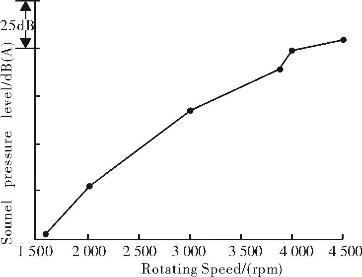
Fig.8 Measured SPL of the TM at various rotating speeds
Generally,atlow Machnumber(Ma< 0.4),aeroacoustic noise can be calculated from the flow field using FW-H Equation[13]whereqis the source of mass,f is the mass force,Tis a tensor related to flow field,corresponding to the intensity of monopole,dipole,and quadrupole sources,respectively.

The noise analysis is based on CFX fan noise analysis. CFX uses Lowson Equation[14],which is developed from Lighthill Equation by taking into account the movement(velocity and acceleration)of noise source and interaction between fluid and moving surfaces.Based on CFD results,CFX is able to calculate the aerodynamic forces on the blades and obtain the noise sources.Then,the propagation path is computed between the source and the observer for SPL at locations of interest.
At 4 500rpm,the 7-blades fan in the TM has a Blade Passing Frequency(BPF)of 525Hz.The first 10 harmonics of the BPF is calculated,as shown in Fig.9.Sound Power LevelLpat base frequency 525 Hz is the highest among the 10 harmonics andLpdecreases with the growth of the harmonic order.Lpat the second order harmonics(1 575 Hz)is over 10 dB lower than base frequency,which means that the second and higher order harmonics of BPF contribute little to the total discrete noise.

Fig.9 Discrete noise spectra of TM at 4 500 rpm

Fig.10 Surface of 95%sound intensity(in red)
Broadband noise[15-16]is calculated and the sound intensity varies spatially inside the blower,as shown in Fig. 10.Surface of 95%sound intensity indicates the locations with highest broadband noise.The highest noise occurs around the area between 180°and 225°inside the fan,where the strongest vortex and backflow is observed. Compared with the streamline distribution in Fig.6(c)at the center plain,there is obvious velocity gradient around the same area.
The decay characteristics and underlying mechanism of the aeroacoustic noise are analyzed,the main noise source is identified as dipole,indicating that turbulence and vortex shedding around blade trailing edge is the main reason for the noise at high rotating speed.The spatial distribution of dipole is illustrated in Fig.11.The highest dipole strength is on the pressure side of the blade near the tip of impeller.Therefore,it is related with the rotating speed,and might be in linear relation with the rotating speed,corresponding to Fig.8.
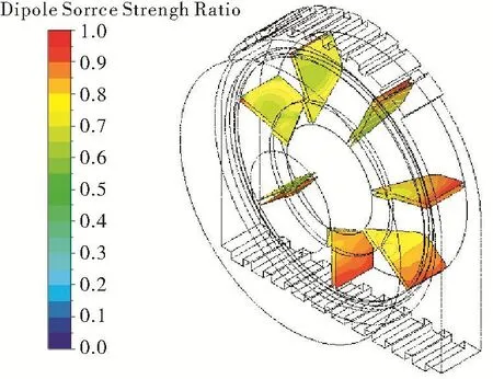
Fig.11 Distribution of dipole on blades
3 Conclusions
In this paper,a hybrid method based on CFD simulation and acoustic analogy is presented for studying aerodynamic performance and aeroacoustic noise of TMs. The main conclusions are:
1)CFD simulation results show that,in the upper half(0°to 180°)and areas between blades,non-uniform airflow produces considerable whirls and vortexes,leading to low totalpressure efficiency ofthe impellerand high aeroacoustic noise.
2)The narrow gap between the impeller tip and casingencumbers the motor case to maintain the pressure rise. The impeller’s capability of raising pressure is not efficiently utilized.
3)Sound field,including discrete and broadband noise sources are computed from CFD results using Lowson Equation embedded in the CFX software.The main component of discrete noise is at base frequency,the second and higher order harmonics of BPF contribute little the total discrete noise.
4)High sound intensity occurs at the area that the flow cross section sharply changes,where strongest turbulence and vortexes occur.The main noise source of the fan impeller is identified as dipole,indicating that turbulence and the shedding vortex is the main reason for the aeroacoustic noise.
Based on the CFD results,flow loss and noise reduction measures are proposed as follows:(i)Reduce airflow velocity by increasing cross-section area of the flow paths,especially the inlet of the impeller;(ii)Add flow guiding vanes to reduce flow velocity gradients around the outlet.
[1]Baonan Gu and Xiafei Ye.Urban Rail Transit Engineering[M]. Huzhong University of Science and Technology Press.2015.
[2]Hongqi Tian.Train Aerodynamics[M].Beijing:China Railway Publishing House.2007.
[3]Weikang Jiang,Haibin Yan,and Li Yan.Analysis and reduction techniques for noise of lifted railway transportation[J].Technical Acoustics,2012,31(2):138-146.
[4]K.M.Boyer and W.F.O’Brien.An improved Streamline Curvature Approach for Off-Design Analysis of Transonic Axial Compression Systems[J].Journal of Turbomachinery,2003,125(3):475-481.
[5]Danqun Fang,Bin Zhang,Jiaqi Sun,and Weijian Lu.Noise Control Engineering[M].Science Press,2013.
[6]Benmeng Shen.Traction Motors[M].Beijing:China Railway Publishing House,2010.
[7]J.Le Besnerais,V.Lanfranchi,and M.Hecquet.Characterization and Reduction of Audible Magnetic Noise Due to PWM Supply in Induction Machines.[J]. IEEE Transactions on Industrial Electronics,2010,57(4):1288-1295.
[8]M.Rogera.Broad band fan noise prediction using single-airfoil theory[C].Fan Noise 2ndInternational Symposium,Senlis,France,2003.
[9]J.D.Anderson and J.Wendt.Computational Fluid Dynamics[M]. New York:McGraw-Hill.1995.
[10]T.J.Chung.Computational Fluid Dynamics[M].Cambridge University Press,2010.
[11]Min Liu,Jia-Bing Wang,and Ke-Qi Wu.Performance and Noise Prediction of Variable Pitch Cross Flow Fans by Numerical Simulation[J].Journal of Engineering Thermophysics,2007,28(2):211-214.
[12]Yijun Mao,Datong Qi,and Qiuhong Liu.Analysis of the Aeroacoustics in Centrifugal Fan Based on Numerical Simulation of Unsteady Viscous Flow [J].Journal of Xi’an Jiao Tong University,2005,39(9):989-993.
[13]J.E.Ffowes-Williams,D.L.Hawkings.Sound Generated by Turbulence and Surfaces in Arbitrary Motion[J].Philosophical Transactions of the Royal Society,A264(1151),1969.
[14]M.V.Lowson.Theoretical analysis of compressor noise[J].Journal of Acoustical Society of America,1970,V47:371-385.
[15]Shuhua Wei,and Tingjun Yang.Design of the High-Efficiency and Low-Noise Blade of the Main Fan[J].Chinese Journal of Turbomachinery,2011(2):38-39.
[16]Qiuhong Liu,Xuejun Wang.A Preliminary Numerical Analysis of the Effect of the Volute Casing on the Aerodynamic Noise inside a Centrifugal Fan[J].Chinese Journal of Turbomachinery,2011(1):3-7.
Aerodynamic and Aeroacoustic Performance Prediction of a Centrifugal Fan in a Railroad Traction Motor Using Hybrid Methods
Zheng Shen1Tong Wang2
(1.CRRC Zhuzhou Electric Co.Ltd;2.School of Mechanical Engineering,Shanghai Jiao Tong University)
Traction motors(TM)are the main power provider for railroad vehicles,which generate considerable noise at high rotational speeds.To improve the aerodynamic performance and reduce the aeroacoustic noise,hybrid methods based on CFD predictions and an acoustic analogy is used to calculate the internal flow field and the flow-induced noise of the motor. The aerodynamic performance of the TM at 3 rotating speeds is obtained.The internal flow field and major aeroacoustic noise sources of the TM are analyzed and visualized.Finally,guidelines for the modification of the fan and the flow path design are proposed to enhance the flow efficiency and reduce the aeroacoustic noise.
Hybrid method,CFD,acoustic analogy,aerodynamic performance,aeroacoustic noise
TH452;TK05
1006-8155-(2017)04-0013-07
A
10.16492/j.fjjs.2017.04.0003
2017-05-04 上海 200240
