Static and Dynamic Analysis of a Novel Single-DOF Six-bar Mechanical Press Mechanism
2017-08-07CHENXiulongGAOWenhuaJIANGShuaiSONGHaoGOUYanyan
CHEN Xiulong, GAO Wenhua, JIANG Shuai, SONG Hao,GOU Yanyan
(1.College of Mechanical and Electronic Engineering, Shandong University of Science and Technology,Qingdao,Shandong 266590, China; 2.Department of Mechanical and Electronic Engineering, Taishan Vocational and Technical College, Taian, Shandong 271000, China)
Static and Dynamic Analysis of a Novel Single-DOF Six-bar Mechanical Press Mechanism
CHEN Xiulong1, GAO Wenhua1, JIANG Shuai1, SONG Hao1,GOU Yanyan2
(1.College of Mechanical and Electronic Engineering, Shandong University of Science and Technology,Qingdao,Shandong 266590, China; 2.Department of Mechanical and Electronic Engineering, Taishan Vocational and Technical College, Taian, Shandong 271000, China)
In this paper, a novel single-DOF six-bar mechanical press mechanism is proposed. In order to realize the static and dynamic analysis of this six-bar mechanism, a kinematic model was established by complex number vector method. The kinetostatic equation and kinetic equation of the mechanism were established by D’Alembert Principle and Lagrange Method respectively. Finally, theoretical computation and simulation were carried out by using MATLAB and ADAMS virtual prototype respectively to obtain the curves ofthe position, velocity andacceleration of the slider, and the changing curves of the balance moment and driving torque of the articulate. The research can not only provide theoretical basis for kinematic analysis, the solution and physical design of balance moment and driving torque of the six-bar mechanism, but it can also provide an effective method for the static and kinematic analyses of other multi-link mechanisms.
six-bar mechanism;kinematic analysis; statics; dynamics
As a new type of forging equipment,multi-link mechanical press has the advantages of high working accuracy, good operation, excellent dynamic performance and high production efficiency[1-3]. Nowmulti-link mechanical press has been applied in many important fields[4-5], such as automotive, military, aerospace, etc.
Static and dynamic analyses of multi-link mechanical press mechanism, which is the foundation of study on stiffness and control system design, can also provide an important theoretical basis for structure design of the mechanism. Up to now, domestic and overseas scholars have done a large number of researches on multi-link mechanism and achieved a series of research results in these areas[6-10]. Du et al.[11]designed a new type of hybrid driven seven bar press mechanism, which realized the journey and velocity control of the working table of the press. Guo et al.[12]studied on the trajectory planning and optimization of the variable velocity servo motor drive crank, using hybrid servo presses of feedback control, to achieve different stamping movement. Li et al.[13]put forward the idea of hybrid driven press, and introduced the characteristics of the hybrid drive machine, and the feasibility of the research of hybrid drive machine is prospected. Zhou et al.[14]studied the optimization of main driving mechanism for servo-punch press. However, there have been few efforts made oriented to analytical modeling which contains kinematic model, kinetostatics model and dynamic model at the same time. Then the static and dynamic analyses have not been sufficiently considered.
This paper takes a six-bar mechanism as an example, the analytical models of the mechanism are established, and kinematics and force analysis of the mechanism are carried out. Based on the kinematic analysis, the displacement, velocity and acceleration equations of the press are derived by using the complex vector method.Considering the gravity and inertia force of each component, the dynamic and statics analysis of the six-bar mechanical press is carried out.And the dynamic model of the press is established by using Lagrange method. Finally, by numerical computation and virtual prototype simulation, the correctness of the analytical models is verified. According to this, the structure model of the six-bar mechanical press is designed, as shown in Fig.1.
1 Kinematics model of the six-bar mechanical press mechanism
1.1 Architectural feature of the six-bar mechanism
As shown in Fig.1, this novel six-bar mechanism which is proposed in this paper includes Frame 1, Crank 2, Linkage 3, Quarter Panel 4, Linkage 5 and Slider 6. Crank 2 and Quarter Panel 4 are respectively connected with a machine frame through a revolute joint;Crank 2 is connected with servo motor and driven by the motor; Linkage 3 is connected with Crank 2 through a revolute joint; Linkage 3 and Linkage 5 are respectively connected with Quarter Panel 4 through a revolute joint; the end of Linkage 5 is connected with Slider 6 through a revolute joint;Slider 6 is in the fixed guide rail, which can move only in the vertical direction. The degree of freedom of the mechanism is one, and the motion of the mechanism can be driven by Crank 2. The structure chart of six-link mechanical press is shown in Fig.2.
1.2 Displacement model of the mechanism

(1)

Fig.1 Structure diagram of six bar mechanism
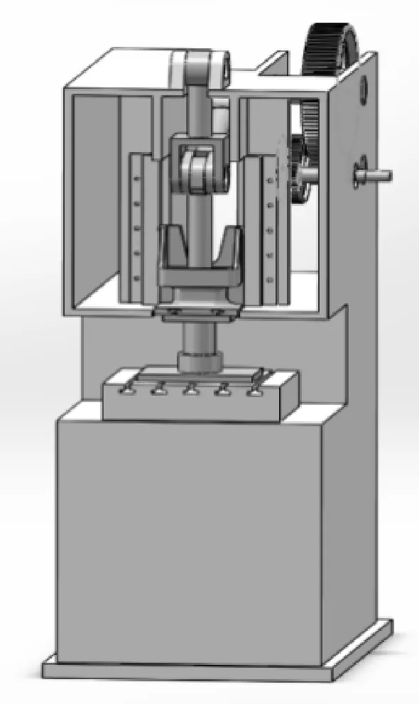
Fig.2 Structure chart of six-link mechanical press
From Formula(1), we can obtain
(2)
In the Formula(2), the motion law of Crank 2 and the length of each member are known. Therefore, three unknown direction anglesθ3,θ4,θ5and the displacement of the sliderS6are given by
(3)
Where,L1,L2,L3,L41,L42,L5,L,S6,αare the dimension parameters of the mechanism as shown in Fig.1.

1.3 Velocity model of the mechanism
Taking first derivative of Formula(2) with respect to time, we can get
(4)
Where,ωiis the angular velocity of the linki,V6is the velocity of Slider 6.
1.4 Acceleration model of the mechanism
Taking the second derivative of equation (2) with respect to time, the acceleration of the six-bar mechanism can be expressed as
(5)
Where,αiis the angular acceleration velocity of the linki,a6is the acceleration of Slider 6.
2 Kinetostatics model of the six-bar mechanical press mechanism
2.1 Kinetostatics modeling of the mechanism
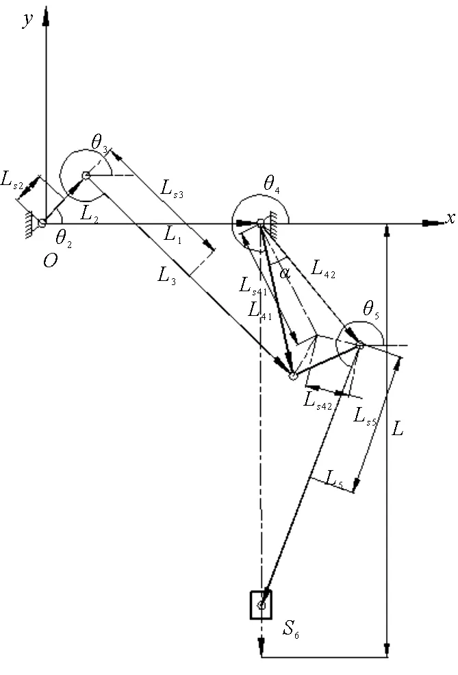
Fig.3 Schematic diagram of single DOF six-bar mechanism

The force analysis of Crank 2, Link 3, Link 4, Link 5 and Slider 6 are shown in Fig.4, Fig.5, Fig.6, Fig.7, Fig.8 respectively.

Fig.4 Force analysis of crank

Fig.5 Force analysis of Link 3

Fig.6 Force analysis of quarter panel

Fig.7 Force analysis of linkage

Fig.8 Force analysis of slider
Through the analysis of the above five components, we can make a list of the fourteen balance equations. Because the Fourteen equations are linear equations, it can be sorted into the following matrix in accordance with the order of unknown forces on the members 2, 3, 4, 5, 6, and so on. Then we can get
CF=D.
(6)


3 Dynamics model of the six-bar mechanical press mechanism
3.1Generalizedcoordinatesofthemechanism
FromFig.2,Crank2isthedrivinglinkinthesingledegreeoffreedomsix-barmechanism.WhentheangulardisplacementofCrank2isgiven,thepositionofthewholemechanismisalsodetermined,andthus,theangulardisplacementofthecrankcanbetakenasthegeneralizedcoordinates,thatisq=θ2.
TheLagrangeformulaforasingledegreeoffreedomsystemisexpressedas
(7)
Where,E,V,Q,qare the kinetic energy, potential energy, generalized force and generalized coordinates of the system, respectively.
3.2 The Lagrange dynamic equation of the mechanism
3.2.1 Motion analysis of the mechanism
To calculate the kinetic energy of the mechanism, we must know the angular velocity and the velocity of the center of mass of each member.By kinematic analysis of the mechanism, we can get
(8)
Whereθiis the angular displacement of componenti,xSiandySiare the coordinates of the centroid of the component in thexaxis andyaxis.


(9)
(10)
The velocity of the center of massSican be given by
(11)
3.2.2 Kinetic energy of the mechanism
The kinetic energy can be expressed as
(12)
By substituting equation (9) and (11) into equation (12), the kinetic energy of the system can be given by

(13)

3.2.3 Potential energy of the mechanism
The zero potential energy position is located at the origin of the coordinate (see Fig.3), the positive direction of the Y axis is the direction of gravity, the potential energy of the system is written as
V=m2gys2+m3gys3+m4gys4+m5gys5+m6gys6.
(14)
3.2.4Generalizedforceofthemechanism
Thegeneralizedforcecanbedeterminedaccordingtothevirtualworkprinciple.Forasingledegreeoffreedomsix-barmechanism,therelationshipbetweenthevirtualworkδ Wofactiveforceandthegeneralizedvirtualdisplacementcanbegivenby
δW=Qδq .
(15)
Where,thecoefficientQinfrontofgeneralizedvirtualdisplacementisgeneralizedforce.
Forthesingledegreeoffreedomsix-barmechanism,accordingtothevirtualworkprinciple,wecanget
(16)
From the equation (16), the generalized force of the system is given by
(17)
Where, M2isthetorqueofthemotoractingonthecrank,S6isthedisplacementoftheslider.
3.2.5Motiondifferentialequationofthemechanism


(18)
(19)
According to the equation(14) we can get
(20)
Take formula(17), (18), (19) and (20) into Lagrange equation (7) and simplify it, the dynamic equation of the novel six-bar mechanism is expressed as
(21)
4 Example of kinematic and force analysis of the six-bar mechanical press mechanism
4.1 System parameters of the mechanism
System parameters of the six-bar mechanism are shown in Tab.1.

Tab.1 System parameters of the six-bar mechanism
4.2 Example of kinematic analysis
When Crank 2 of the six-bar mechanism runs three cycles, the displacement curve of Slider 6 obtained by the numerical calculation of MATLAB and the displacement curve of Slider 9 obtained by the virtual proto type of ADAMS are shown in Fig.9. The velocity curve of Slider 6 obtained by the numerical calculation of MATLAB and the velocity curve of Slider 6 obtained by the virtual prototype of ADAMS are shown in Fig.10. The acceleration curve of Slider 6 obtained by the numerical calculation of MATLAB and the acceleration curve of Slider 6 obtained by the virtual prototype of ADAMS are shown in Fig.11.
From Fig.9 to Fig.11, the trend and the peak value of the displacement curves, velocity curves, and acceleration curves are basically similar; the maximum error of the displacement, which occurs in 1.58 s, is 0.000 4 m; the maximum error of the velocity, which occurs in 1.98 s, is 0.000 3 m/s; the maximum error of the acceleration, which occurs in 1.64 s, is 0.000 5 m/s2.

Fig.9 The displacement of six-bar mechanism’s slider
4.3 Example of kinetostatics analysis
When Slider 6 of the six-bar mechanism moves with no-load, that isFr=0, the balance moment curves of crank of mechanism obtained by the numerical calculation of MATLAB and the balance moment curves of crank of mechanism obtained by the virtual prototype of ADAMS are shown in Fig.12. When Slider 6 of the six-bar mechanism moves with load, that isFr=100 kN, the balance moment curves of crank of mechanism obtained by the numerical calculation of MATLAB and the balance moment curves of crank of mechanism obtained by the virtual prototype of ADAMS are shown in Fig.13. The numerical calculation of the bearing reaction between Linkage 5 and Slider 6 and the virtual prototype simulation of the constraint force between Linkage 5 and Slider 6 are shown in Fig.14.

Fig.10 The velocity of six-bar mechanism’s slider

Fig.11 The acceleration of six-bar mechanism’s slider

Fig.12 The balance moment of the six-bar mechanism when the slider has no load
From Fig.12 to Fig.14, the trend of MATLAB calculation result is consistent with the ADAMS virtual simulation result; when Slider 6 of the six-bar mechanism runs with no-load, the maximum error of the balance moment, which occurs in 1.28 s, is 0.198 2 N·m; when Slider 6 of the six-bar mechanism runs with load, the maximum error of the balance moment, which occurs in 1.98 s, is 14.332 4 N·m; when Slider 6 of the six-bar mechanism runs with load, the maximum error of the constraint force between Linkage 5 and Slider 6, which occurs in 1.58 s, is 30 N.

Fig.13 The balance moment of the six-bar mechanism when the slider has load

Fig.14 The constraint force between Linkage 5 and Slider 6 when the slider has load
4.4 Example of dynamics analysis
When Slider 6 of the six-bar mechanism moves with no-load, that isFr=0, the numerical calculation of the driving torque of the crank obtained by MATLAB and the virtual prototype simulation of the driving torque of the crank obtained by ADAMS are shown in Fig.15. When Slider 6 of the six-bar mechanism runs with load, that isFr=100 kN, The numerical calculation of the driving torque of the crank obtained by MATLAB and the virtual prototype simulation of the driving torque of the crank obtained by ADAMS are shown in Fig.16.

Fig.15 The driving torque of the six-bar mechanism when the slider has no load

Fig.16 The driving torque of the six-bar mechanism when the slider has load
From Fig.15 to Fig.16, the trend of numerical calculation result is consistent with the virtual simulation result.When Slider 6 of the six-bar mechanism runs with no-load, the maximum error of the driving torque, which occurs in 1.26 s, is 0.058 8 N·m.When the slider 6 of six-bar mechanism runs with load, the maximum error of the driving torque, which occurs in 1.98 s, is 10.332 4 N·m.
5 Conclusions
1) A novel single-DOF six bar mechanical press mechanism is proposed.The kinematic model of this novel six-bar mechanism is established by using the complex vector method; the kinematic analysis including slider position, slider velocity, and slider acceleration is realized and verified by numerical calculation and virtual simulation.
2) The kinetostatics model of the six-bar mechanism is established by using the matrix method, the constraint force of joints and balance moment are studied and verified.
3) The dynamic model of the six-bar mechanism is established by using the Lagrange Method. The driving torque on crank is solved and verified.
4) This study can not only provide theoretical basis for kinematic analysis, force analysis and structure design of the six-bar mechanism, but also suggest a way of static and dynamic analysis for other multi-link mechanisms.
[1]TSO P L,LIANG K C.A nine-bar linkage for mechanical forming presses[J].International Journal of Machine Tools & Manufacture,2002,42(1):139-145.
[2]LIN W Q,LI Z S,LI J P,et al.Optimization method for movement of multi-bar press based on genetic algorithm[J].Forging & Stamping Technology,2011,36(5):81-84.
[3]GE Z H,MA W J,ZHANG K K,et al.Mechanism design and dynamic analysis of hybrid cam-linkage mechanical press[J].Key Engineering Materials,2011,474-476:803-806.
[4]SONG Q,LI J,YIN W.Mechanical press six-link mechanism design based on multi-objective[J].Transactions of the Chinese Society for Agricultural Machinery,2012,43(4):225-234.
[5]GAO X.Mechanical behavior study of six-bar press[J].Machine Design & Research,2013,29 (4):143-146.
[6]LU X J,ZHU S H,HE G J,et al.Kinematic analysis of multi-link high-speed presses[J].China Mechanical Engineering,2011(11):1297-1301.
[7]HE Y P,Zhao S D,Zou J,et al.Research on hybrid input mechanical press driven by two motors[J].International Journal of Mining Science and Technology,2006,16(1):57-60.
[8]LU X J,KE Z M,ZHU S H,et al.Research on slider motion curves of multi-link high-speed press based on virtual prototype technology[J].Forging & Stamping Technology,2010,35(4):90-94.
[9]BALASUBRAMANYAM C,SHETTY A B,SPANDANA K R,et al.Analysis and optimization of an 8 bar mechanism[J].International Journal of Machine Learning and Cybernetics,2015,6(4):655-666.
[10]KIRECCI A,DULGER L C.A study on a hybrid actuator[J].Mechanism & Machine Theory,2000,35(8):1141-1149.
[11]DU R,GUO W Z.The Design of a new metal forming press with controllable mechanism[J].Journal of Mechanical Design,2003,125(3):582-592.
[12]GUO W Z,HE K,YEUNG K,et al.A new type of controllable mechanical press:Motion control and experiment validation[J].Journal of Manufacturing Science & Engineering,2005,127(4):731-742.
[13]LI H,ZHANG C,MENG C.Hybrid-driven nine-bar press for precision drawing[J].Chinese Journal of Mechanical Engineering,2004,17(S):197-200.
[14]ZHOU Y.Type synthesis and optimization of main driving mechanism for servo-punch press[J].Journal of Mechanical Engineering,2015,51(11):1-7.
(责任编辑:李 磊)
2017-03-02
国家自然科学基金项目(51005138);山东省优秀中青年科学家奖励基金项目(BS2012ZZ008)
陈修龙(1976—),男,河北沧州人,副教授,博士,博士生导师,主要从事机构学理论和应用技术的研究. E-mail:cxldy99@163.com
新型单自由度六连杆机械压力机机构的静力学及动力学分析
陈修龙1,高文花1,姜 帅1,宋 浩1,苟岩岩2
(1.山东科技大学 机械电子工程学院,山东 青岛 266590; 2.泰山职业技术学院 机电工程系,山东 泰安 271000)
提出了一种新型的单自由度六连杆机械压力机机构,为了实现机构的动态静力学以及动力学分析,采用复数矢量法建立了机构的运动学模型,基于达朗贝尔原理建立了机构的动态静力学方程,利用拉格朗日法建立了机构的动力学方程;分别利用MATLAB理论计算与ADAMS虚拟样机仿真得到压力机机构中滑块的位置曲线、速度曲线、加速度曲线,以及曲柄的平衡力矩和驱动力矩变化曲线。研究不仅为六连杆压力机运动学分析、平衡力矩和驱动力矩的求解和结构设计提供了理论依据,也为其他压力机机构的静力学和动力学分析提供了有效方法。
六连杆机构;运动学分析;静力学;动力学
TH112
A
1672-3767(2017)05-0080-11
10.16452/j.cnki.sdkjzk.2017.05.012
