Analysis of Modal Stall Inception in Compressors Based on Phase Difference of Wavelet Transforms
2017-07-21XiangXueTongWangJonghoAnGasTurbineResearchInstituteShanghaiJiaoTongUniversityKimChaekPolytechnicalUniversity
XiangXueTong WangJong ho An(.Gas Turbine Research Institute,Shanghai Jiao Tong University;.Kim Chaek Polytechnical University)
Analysis of Modal Stall Inception in Compressors Based on Phase Difference of Wavelet Transforms
XiangXue1Tong Wang1Jong ho An2
(1.Gas Turbine Research Institute,Shanghai Jiao Tong University;2.Kim Chaek Polytechnical University)
The detection and analysis of modal waves in compressors are important,since they occur as stall inception prior to stall.Wavelet analysis enjoys growing popularity as a method to investigate stall inception,few researchers,however,have focused on the original equation of wavelet transform.Based on the deep understanding of previous theories about modal stall and the deduction of wavelet transforms,a new method is proposed to analyze the characteristics of modal waves.The method technically requires the data acquisition from dynamic pressure transducers mounted flush circumferential near the impeller inlet or outlet.When two specific conditions of wavelet transforms are satisfied,the modal number and rotational
stall inception,modal stall,compressor,Wavelet transform
0 Introduction
Rotating stall is a typical unstable flow phenomenon in compressors.When it occurs,flow separation appears in some specific impeller channels or diffuser and stall cells travels along the rotational direction of the rotor with a relatively low rotational speed[1].Rotating stall may shorten lifespan of the blades,trigger surge and even bring some more serious damages.Thus,the study about the stall mechanism in compressors has always been emphasized.
In 1945,Cheshire[2]observed the stall phenomenon in a low-speed centrifugal compressor diffuser.In 1964,Jansen[3]showed that the unsteady flow caused the threedimensional flow separation,which triggered stall in the vaneless diffuser and the position of separation depended on both inlet Reynolds number and the diffuser geometry.From 1980 to 1990,the experimental studies in the axial compressors carried out by McDougall[4],Day[5]and Garnier[6],stall inceptions are basically divided into two types:one is the modal wave,another is the spike.In 1986,Moore and Greitzer[7-8]proposed Moore-Greitzer model to analyze rotating stall and surge in axial compressors,which indicated that stall is induced by the typical disturbance.In 1990,McCaughan[9]used the bifurcation theory to simplify the Moore-Greitzer model and proposed the difference between classic surge and deep surge.
Recently,the characteristics of stall in compressors have been investigated by many researchers through experiments.Spakovsky[10-11]carried out the experiments in centrifugal compressors and analyzed the characteristics of the two kinds of stall waves.Usually,the stall modal wave that is not fully developed have a small amplitude and a large wavelength.It is generally believed that its rotating speed is roughly equivalent to 20%~40%of impeller rotationalspeed.Whenfullydeveloped,its rotating speed is more than 40%of impeller rotational speed.Thespikegenerallyoccursinsomecertain situations.For example,it may occur when the blade tipoccuvs clearance in axial compressors changes or the flow leakage between the impeller and the diffuser in centrifugal compressors.The rotating speed of spikes is generally 60%~80%of the impeller rotational speed.Since stall wave are always found at the impeller inlet or outlet in compressors,especially the modal wave,the measuring points in experiments are always arranged on the circumference at the impeller inlet or outlet to investigate the modal wave.Through determining the mode of circumferential pressure fluctuation,the characteristics of modal waves can be obtained and the instability of compressors would be further explored.The modal schematic diagram of stall wave is as shown in Fig.1.
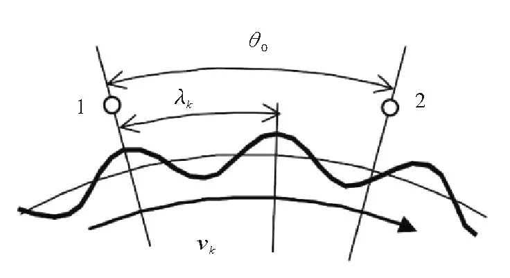
Fig.1Modal schematic diagram of stall wave
Where,vkis the rotational speed of stall waves,andλkis the wave length of stall waves.
The characteristics of modalwavesinlow-speed centrifugal compressors were investigated by Lawless and Fleeter[12].Eight pressure transducers at impeller inlet were uniformly arranged circumferentially and their signals were analyzed by means of the time-spatial Fourier transformanalysis.Accordingtotheirresearch,the relationship between the frequencyf0and rotational speedvkof stall wave is as follows:

Where,n0is the modal number of stall waves.
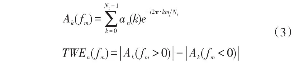
The time-spatial Fourier transform analysis was also used to analyze the modal waves in a high-speed centrifugal compressor by Oakes[13-14].The time-spatial discrete Fourier transform expression of the circumferential pressure sensor signalPis as follows:

Then,the wave energyTWEn(fm)was acquired through the time-spatial discrete Fourier transform within a limited time window to detect a rotating stall wave by Trifonidis[15]:
In order to determine the rotational speed of stall waves,spatial correlation method(SCM)was used by Cameron and Morris[16]to investigate the characteristics of stall waves at the impeller inlet.The standard crosscorrelation functionRX(τ,t0)is proposed as follows:

Fourier transform is generally used to analyze the discrete frequency components of signals within a period of time,while Wavelet transform can be used to analyze timefrequency characteristics in a shorter period of time and is more suitable for the analysis of non-stationary pressure signals during rotating stall or surge.Including the modal waves,Wavelet transform can also be used to capture the spikes that Fourier transform analysis can hardly do.The Morlet continuous Wavelet transform was used by Li and Chen[17]to analyze the rotational speed of rotating stall waveinaxialcompressors.ThefunctionofMorlet continuous Wavelet transform is as follows:

If the signals are discrete,the following formula can be used to process continuous Wavelet transform:

Wavelet transforms are becoming more and more popular these years and many researchers use it as a method to investigate stall inception in compressors or fans[18-21].Especially,Horodko[22-23]used the Wavelet cross-correlation function to investigate the characteristics of rotating stall waves in a centrifugal compressor after measuring two velocity signals at impeller outlet.This Wavelet cross-correlation functionWCC(s,τ)is proposed:

WCC(s,τ)will reach the maximum value when the time interval of two sensor signals is a certain phase timeτ0,and at this time the rotational speedvkof stall waves can be determined by the following equation:

Where,mis the number of stall wave bands with the complete wavelengthλkbetween circumferentially adjacent sensors.
For example,in the case shown in Fig.1,m=1,because of the only one stall wave band with a complete wavelength between the measuring point 1 and 2.Since the number of stall wave bands with the complete wavelengths in a closed circumference must be an integer,λk=2π/n0andn0is an integer.This correlation function was also used to analyze the unsteady pressure fluctuation in a centrifugal pump by Pavesi[24].
It is obvious that further it is necessary to deeply study.Inordertopreventrotatingstallorsurge,a convenient method needs to be proposed to judge whether a wave component is the modal stall wave inception and obtain the features of modal waves.It can also contribute a lot to the mechanism research of stall or surge generation.
1 Analysis Based on Phase Difference of Wavelet Transform
Dynamicpressuresignalsofeighttransducers uniformly mounted circumferentially at the impeller inlet of an axial compressor were measured during stall by Cameron and Morris,and the data low-pass filtered to 5Nris as shown in Fig.2.The modal stall wave was clearly captured in the experiment and the features of the modal wave were obtained by four kinds of traditional analytical methods,such as spatial Fourier decomposition[16].
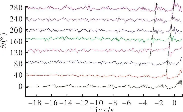
Fig.2Pressure signals low-pass filtered at 5Nr
Where,Nris impeller rotation frequency.
At first,the frequency of modal stall wave needs to be obtained.Inthefrequencydomainanalysis,Fourier transformhasagoodfrequency-locating capability,especially for those deterministic signals with relatively simple frequency components.However,even the shorttime Fourier transform(STFT)is mainly dependent on the time width of the signal.While the time width in Wavelet transform can be changed with the scale,so that it has a better local analysis ability.Thus,in the analysis of modal stall waves which are typical unsteady signals,the Wavelet transform is chosen,instead of the Fourier transform.The continuous Wavelet transform as shown in Eq.(5)is used.Wavelet transformWT(s,b)corresponds various components to specific scalesand time parameterb.The frequencyfof each component can be indicated as follows:

Where,αis a parameter for adjusting frequency resolution.
Using this frequency expression can improve the resolution of the relatively low frequency range,which is an important region in this study.With an appropriate parameterbselected,the amplitude of wavelet transform is relatively large at a certain frequency which is less than the frequency of impeller rotational speed.The frequency can be considered as the frequency of modal stall wave.Fig.3 is the time-frequency spectrum of pressure data with installation angle of 0°in Fig.2,which is obtained by Wavelet transform.
According to Eq.(9),the frequencyf0of stall wave component can be obtained,and the angular velocityΩ0=2πf0can be further calculated.Additionally,it is obvious that the magnitude of the stall wave component withf=f0increases untilt=-8 rev and then decreases in this timefrequency spectrum,which cannot be observed in the original pressure signal diagram.In order to determine the rotating speedvkof stall modal wave,the signal phase of each two adjacent sensors needs to be calculated.In general,the performanceformulaofpressuresignalisasfollows:

Fig.3Time-frequency spectrum of pressure data with the installation angle of 0°

Since Shannon Wavelet transform can reflect the phase of each frequency component well,it is selected to analyze the stall wave component.The generating functionψ(t)of Shannon Wavelet transform is as follows:

Eq.(10)and(11)aresubstitutedintoEq.(5)asfollows:
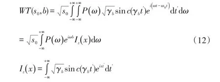
Where,t'=(t-b)/s0,x=ω·s0-ω0.
The functionIz(x)can be expanded into the following expression:

Substituting Eq.(13)into Eq.(12),the following expression can be obtained:

In Eq.(14),ω1=Ω0-π·γb/s0,ω2=Ω0+π·γb/s0,and the amplitude of stall wave component is the largest atω=Ω0within the angular velocity segment[ω1,ω2],as shown in Fig.4.

Fig.4Stall wave component in Wavelet transform
In this case,two reasonable conditions need to be emphasized:
(1)Within the angular velocity segment[ω1,ω2],the amplitude value of Wavelet transformP(ω)is symmetrical about the angular velocityω=Ω0;
(2)Since the angular velocity segment[ω1,ω2]is small,the phase difference of Wavelet transform has a linear relationship with the different ang angular velocity shown as follows:

The Eq.(15)andΩ=ω-Ω0is substituted into Eq.(14),finishing:

In Eq.(16),it is seen that Shannon Wavelet phaseФ(s0,b)of the scales0is equal to what is the stall wave phaseφ(Ω0)plusΩ0·b,shown as follows:

With the time parameterb1is selected,the stall wave component phases of two adjoining sensors areφ1(Ω0)andφ2(Ω0).The stall wave component phaseφ1(Ω0)of a sensor prior to a period of timeτ0(Δb=[φ2(Ω0)-φ1(Ω0)]/Ω0)is equal to the stall wave component phaseφ2(Ω0)of the circumferential adjacent sensor.Furthermore,according to Eq.(17),it can be deduced that the stall wave component phases of circumferential adjacent sensors in this case have the following relationship.

It is shown that the stall wave component phase difference between circumferential two adjacent measuring points is equal to the phase difference of Shannon wavelet transform.And the phase difference corresponds to a period of timeτ0,as shown in Fig.5.

Fig.5Phase of two signals in Wavelet transform
Next,the phase difference of Wavelet transform is used to investigate the modal numbern0and the rotational speedvkof stall wave.Both sides of Eq.(8)are multiplied by the modal numbern0of stall wave component under the scales0,and then Eq.(1)is substituted into it,finishing:

Where,int(x)is a function of rounding to the nearest integer andθ0is central angle between two circumferential adjacent measuring points.
Substituting Eq.(18),it can continue to be derived as follows:

n0can be represented as:

Where,kis a non-negative integer andk1is less than 2π/θ0.
Then,kcanbeacquiredbytheprogrammingcalculationandn0canbeexpressedas:
Finally,substituting the modal numbern0into Eq.(1),the rotational speedvkof stall waves can finally be gained.The frequency of impeller rotational speedNr=244.7Hz and sampling frequencyfN=7 kHz in the experiment which have been processed by Cameron and Morris[16],s0the parametersγbandγcof Shannon Wavelet transform generating functionψ(t)were set as 0.1 and 1.Especially,γb=0.1 can makeΩ1/Ω0=1/20 and the two assumptions satisfied whileγcis selected according to the sampling frequency.
Wavelet transform is used to obtain the timefrequency spectrum of eight measuring pressure signals within the total observing time as shown in Fig.6.Thus,according tos0=72,the frequency of stall wave at each measuring point can be taken asf0=103.4 Hz.

Fig.6Time-frequency spectrum based on Wavelet transform
Fig.7 is the phase curve of Wavelet transformФ(s0,b)over time with the stall wave component frequencyf0.
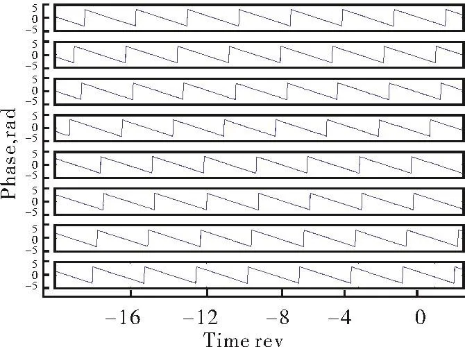
Fig.7Phase curve of signals in Wavelet transform over time
According to the phase difference of each two circumferentially adjacent measuring points,Eq.(22)is used to obtain the modal number curve over time,as shown in Fig.8.
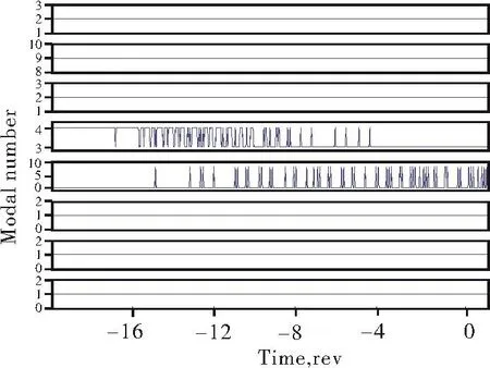
Fig.8Modal number of stall wave
In fact,during the total observing period,the signals inevitably suffer a lot of influence of external factors,such as some noises,which makes the modal numbern0obtained by this analysis method abnormal sometimes.Considering the overall situation,the modal numbern0of the stall modal wave withf0=103.4 Hz is determined as 1.Then according to Eq.(1),the rotational speed of stall wave was further determinedvk=0.4225Nr.The relative deviation betweenvkobtained in Ref.[16]andvkcalculated by this analysis method is only 1.7%,so that it can prove the accuracy and feasibility of this method.
2 ExperimentinaCentrifugalCompressor
After verifying the feasibility of this analysis method in an axial compressor,this approach is also applied in a centrifugal compressors during stall or surge.Thus,a test rig of centrifugal compressor is built to specifically analyze this topic.
2.1 Experimental Facility
The sketch of the centrifugal compressor experimental system is shown in Fig.9.

Fig.9Sketch of the experimental system
The compressor is driven by an electric motor of 90 kW.The rotating speedNdesign=22 790 r/min and design flow rateMdesign=0.64 kg/s.The flow rate is mainly controlled by adjusting the outlet valve.Static pressure and temperature at specific position are obtained in Fig.9 to calculate the overall performance.The precision of the static pressure and temperature measurement are 0.26%and 0.25%respectively.
Some geometry parameters of impeller are as shown in Table 1,and the type of diffuser is the vaneless diffuser.

Tab.1Design parameters of the impeller
In theory,in this case this method obtains the information of stall waves by phase difference,it does not require an all-circumferential arrangement of dynamic pressure sensors.Even just two sensors between a certain circumferentialanglecanmakeitdone.Thus,two circumferential measuring points with a central angle deviation of 7.7°are placed at the impeller outlet as shown in Fig.10.To put it more specific,two Kulite XSC-190M dynamic pressure transducers are mounted on the casing surface at the diffuser outlet.The large amounts of data measured are recorded by PCI-6250 acquisition card with the sample frequency of 20 kHz.Precision of the dynamic pressure measurement is 0.5%.

Fig.10Pressure measuring point
2.2 Experimental Method
Overall performance of this compressor is measured at first.Through it,the flow rate near to surge is obtained.Then,after a period of time of stable running at the design condition,the outlet valve is slowly turned down to make the compressor suffer the surge.When the outlet flowmeter shows that the outlet flow rate declines relatively quickly,it can be acknowledged as the occurrence of surge.When the compressorsuffers surge,the outlet valve needs to be turned up immediately to protect the machine and the compressor can recover to the normal condition.The dynamic pressure data are recorded in the whole process.
3 Experimental Results and Analysis
3.1 Experimental Results
TheoverallperformanceisshowninFig.11,including the pressure ratio and isentropic efficiency curves changing over the volume flow rate.It can be seen that the surge margin isQ/Qdesign=0.76.
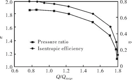
π—pressure ratioη—isentropic efficiencyFig.11Overall performance of the research compressor
The real-time pressure measuring results are shown in Fig.12.There are five typical periods including normal process,turning down outlet throttle value process,stall inception process,surge process and recovery process.The stall inception process is the focus of this research object.

Fig.12Pressure traces within total observing period
At the moment oft=0 rev,it is considered that surge occurred since the outlet flow rate declined quickly and the compressor made a relatively intense sound of oscillation.It can be seen that the obvious stall modal waves replaced the chaotic fluctuation untilt=-40 rev prior to surge point,as shown in Fig.13.

Fig.13Pressure traces from-60 to 15 rev
3.2 Analysis Based on Phase Difference of Wavelet Transform
According to that the sampling frequency is 20 kHz and the impeller rotational speed is 22 790 r/min,which means the impeller rotational frequencyNr=379.83 Hz,the generatingfunctioncoefficientsofShannonWavelet transform are selected asγb=0.01,γc=1 andωr=2πγc=2π.
In order to identify the modal stall wave component more accurately,the impeller rotation frequency component was filtered out by the method of band-block filter.Then the time-frequency spectrum of pressure data is obtained by Wavelet transform,as shown in Fig.14.It can be seen that there are two relatively obvious components withn=46 and 96,corresponding tof=260 and 128 Hz.Several unconspicuous frequencies is not deeply investigated there.It requires a further judgment whather these frequency componewts(f=260,128Hz)belong to modal stall.

Fig.14Time-frequency spectrum based on Wavelet transform
After calculation,modal numbern0withf=260Hz is always 0 during the time period from-60 to 10 rev,while that of 128 Hz is 1 in most of this period.Fig.15 is modal number withf=128 Hz.According to the theory of stall wave,the frequency component with withn0=0 does not belong to stall wave.Therefore,it is determined that 128 Hz is the frequency of stall wave whilef=260 Hz can be seen as the multiplier of 128 Hz but not the frequency of stall wave.

Fig.15Model number of stall wave
Through Wavelet transform,it can be seen that the amplitude of modal wave component significantly increased at the last 30 to 10 revolutions prior to surge,as shown in Fig.16.

Fig.16Amplitude of stall wave based on Wavelet transform
Finally,Eq.(1)is used to determine that the rotational speed of the stall modal wave is 0.3378Nr,which is within the scope between 20%~40%of impeller rotational speed.Thus,the stall wave in this experiment does not fully developed before surge.
4 Conclusions
This paper focuses on both the previous theories about modal wave and the derivation of Wavelet transform.A new method is proposed to determine a wave component is modal stall inception and the features of modal wave was obtained.Some conclusions of this method are as follows:
(a)According to a detailed derivation,the modal wavecomponentphasedifferenceofthetwocircumferential adjacent sensors is equal to the phase differenceofShannonWavelettransformwhenthe symmetry and linearity assumption are satisfied.Therefore,the parameters of Wavelet transform need to be adjusted to satisfy the two assumptions.
(b)The method has been well applied to the stall or surge inception experiments in an axial compressor and a centrifugal compressor respectively,which validates its feasibility.The modal wave component can be accurately captured prior to stall or surge,and the characteristics of modal wave such as modal number and rotational speed can be easily obtained.Meanwhile,based on the modal number,whether a wave component is modal stall inception or not can be determined.
(c)The advantage of this approach lies in the convenience,compared to the traditional analysis methods.Moreover,since this method obtains the information of stall waves by phase difference,it does not require an allcircumferential arrangement of dynamic pressure sensors.Evenjusttwosensorsspacedapartbyaspecific circumferential angle can make it done.It can be applied as a pretreatment method about the modal stall analysis in compressors.
[1]Emmons H W,Pearson C E,Grant H P.Compressor surge and stall propagation[J].Transactions of the ASME,1955,77(4):455-469.
[2]Cheshire L J.The design and development of centrifugal compressors for aircraft gas turbines[J].Proceedings of the institution of mechanical engineers,1945,153(1):426-440.
[3]Jansen W.Rotating stall in a radial vaneless diffuser[J].Transactions of the ASME Journal of Basic Engineering,1964,86(4):750-758.
[4]McDougall N M,Cumpsty N A,Hynes T P.Stall inception in axial compressors[J].Journal of Turbomachinery,1990,112:116-125.
[5]Day I J.Stall inception in axial flow compressors[J].Journal of turbomachinery,1993,115(1):1-9.
[6]Garnier V H,Epstein A H,Greitzer E M.Rotating waves as a stall inception indication in axial compressors[J].Journal of mechanical design,1991,113(2):290-302.
[7]Moor F K,Greitzer E M.A theory of post stall transients in a axial compressor system,part-development of Equation[J].Journal of Engineering for gas turbine and power,1986,108:68-76.
[8]Greitzer E M,Moore F K.A theory of post-stall transients in axial compression systems,part II-Application[J].Journal of engineering for gas turbines and power,1986,108(2):231-239.
[9]McCaughan F E.Bifurcation analysis of axial flow compressor stability[J].SIAM Journal on Applied Mathematics,1990,50(5):1232-1253.
[10]SpakovszkyZS.Backwardtravelingrotatingstallwavesin centrifugal compressors[J].Journal of turbomachinery,2004,126(1):1-12.
[11]Spakovszky Z S,Roduner C H.Spike and modal stall inception in an advanced turbocharger centrifugal compressor[J].Journal of Turbomachinery,2009,131(3):031012.
[12]Lawless P B,Fleeter S.Rotating stall acoustic signature in a lowspeed centrifugal compressor:partⅠ-vaneless diffuser[J].Journal of turbomachinery,1995,117(1):87-96.
[13]Oakes W C,Lawless P B,Fagan J R,et al.High-speed centrifugal compressorsurgeinitiationcharacterization[J].Journalof propulsion and Power,2002,18(5):1012-1018.
[14]Oakes W C,Lawless P B,Fleeter S.Instability pathology of a high speed centrifugal compressor[C]//ASME 1999 International Gas Turbine and Aeroengine Congress and Exhibition.American SocietyofMechanicalEngineers,1999:V004T03A053-V004T03A053.
[15]Tryfonidis M,Etchevers O,Paduano J D,et al.Prestall behavior of several high-speed compressors[J].Journal of Turbomachinery,1995,117(1):62-80.
[16]Cameron J D,Morris S C.Analysis of axial compressor stall inceptionusingunsteadycasingpressuremeasurements[J].Journal of Turbomachinery,2013,135(2):021036.
[17]Liao S,Chen J.Time-frequency analysis of compressor rotating stall by means of Wavelet transform[C]//ASME 1996 International Gas Turbine and Aeroengine Congress and Exhibition.American SocietyofMechanicalEngineers,1996:V001T01A013-V001T01A013.
[18]Salunkhe P B,Pradeep A M.Stall inception mechanism in an axial flow fan under clean and distorted inflows[J].Journal of Fluids Engineering,2010,132(12):121102.
[19]Ziach M,Majkut M,Witkowski A.Application of the Wavelet transform of pressure signals for detecting and analyzing rotating stall inception in axial flow low speed compressor stage[J].Archive of Mechanical Engineering,2011,58(1):61-77.
[20]He X,Ma H,Zhang J,et al.Wavelet analysis of the shaft order perturbation and stall inception in an axial compressor[J].Journal of Thermal Science,2013,22(3):223-228.
[21]Dejene T T,Pradeep A M.Experimental investigation of stall inception mechanisms of low speed contra rotating axial flow fan stage[J].International Journal of Rotating Machinery,2015.
[22]Horodko L.Identification of rotating pressure waves in a centrifugal compressor diffuser by means of the Wavelet crosscorrelation[J].International Journal of Wavelets,Multiresolution and Information Processing,2006,4(2):373-382.
[23]Horodko L.Identification of coherent structure in turbulent shear flow with Wavelet correlation analysis[J].ASME Journal of Fluids Engineering,1998,120:778.
[24]PavesiG,CavazziniG,ArdizzonG.Time-frequencycharacterization of the unsteady phenomena in a centrifugal pump[J].International Journal of Heat and Fluid Flow,2008,29(5):1527-1540.
基于小波变换相位差的压缩机内部模态失速先兆分析∗
薛翔1王彤1安正浩2
(1.上海交通大学燃气轮机研究院;2.金策工业综合大学)
由于模态波经常作为一种失速先兆出现在压缩机发生失速前,因而对它的识别与分析都非常重要。近年来,小波变换被越来越多的研究者用来分析失速先兆,然而很少有人关注小波变换原始的表达式。基于对前人模态失速理论的深刻理解和小波变换的进一步推导,本文提出了一种用来分析模态波特征的新方法。这种方法需要使用叶轮进口或出口附近周向的动态压力数据。而当小波变换的两个特定条件满足时,模态波的模态数和传播速度等可以通过小波变换的相位差得到。该方法的可行性使用已公布的一台轴流压缩机实验数据进行了验证,也同时在一台离心压缩机上进行相关实验。通过该方法,可以判断出动态信号中明显的波动成分属不属于模态失速,同时得到模态波的特征参数。因而,这种新方法可以作为压缩机内部模态失速分析的一种前处理手段。
失速先兆;模态失速;压缩机;小波变换
TH452;TK05
1006-8155-(2017)03-0020-09
A
∗Fund project:Supported by National Natural Science Foundation of China(Grant No.51276108)
date:2017-05-22Shang hai200240
10.16492/j.fjjs.2017.03.0006speed of modal wave can be determined based on the phase difference of the wavelet transform.The feasibility of this method was verified first by using published experimental results in an axial compressor.Then,an experiment in a centrifugal compressor was performed.By applying this method,it was possible to distinguish whether an obvious wave component in the dynamic signal is related to modal stall or not and features of modal waves were obtained.Thus,this new method can be generalized as a pretreatment method for modal stall analysis in compressors.