Ceramic-salt based composites for thermal energy storage
2017-07-12NAVARROMariaElenaPALACIOSAnabelHUGHESTomosCONNOLLYChloeUPPALHarkiranCONGLinLEIXianzhangQIAOGengLENGGuanghuiDINGYulong
NAVARRO Maria Elena, PALACIOS Anabel, HUGHES Tomos, CONNOLLY Chloe, UPPAL Harkiran, CONG Lin, LEI Xianzhang, QIAO Geng,, LENG Guanghui, DING Yulong
Ceramic-salt based composites for thermal energy storage
NAVARRO Maria Elena1, PALACIOS Anabel1, HUGHES Tomos1, CONNOLLY Chloe1, UPPAL Harkiran1, CONG Lin1, LEI Xianzhang2, QIAO Geng1,2, LENG Guanghui1, DING Yulong1
(1School of Chemical Engineering, University of Birmingham, Birmingham B15 2TT, UK;2Global Energy Interconnection Research Institute Europe GmbH, Berlin 10117 , Germany)
This paper reports a study on ceramic based phase change materials (PCM). Sodium nitrate (NaNO3) was used as the PCM, magnesium oxide (MgO) as the ceramic matrix, and different types of carbon materials as the thermal conductivity enhancers (TCE). The composites were fabricated by mixing, compaction, and sintering. The effect of carbon material addition was studied and the morphological and thermophysical properties of the composites were characterized. The results showed that the addition of the TCE could either hinder or enhance the thermal diffusivity of the composites, depending on the type of TCE used. It was found that the thermal energy storage density increased with increasing PCM concentration in the composite. All the composites manufactured were found to be thermally stable up to 500 ℃.
thermal energy storage; phase change material; composites; thermal conductivity enhancer
The global energy demand has been on the rise and is predicted to increase in many years to come. The international energy agency (IEA) projects an increase of ~50% by 2040[1]. Energy management will play a key role in the development of the modern world particularly in terms of sustainable production and use of energy[2]. Fig.1 illustrates energy use situations in the world and projections until 2040. One can see that renewable energy sources including solar, wind, geothermal and biomass only account for a small percentage of the world’s energy consumption in 2013, and the projected share for the renewables is set to increase to between 20%—30% in 2040. In the last decades, a huge effort has been made from bothscientific and industrial communities supported by governments [3] to increase the share of renewable energies in the worldwide energy mix. It is widely agreed that the use of renewable energy sources will eventually lead to enhancement of environment and energy efficiency, reduction of our dependence oncarbon based fossil fuels, and improvement of energy security.
Energy storage refers to a process that stores energy for use in a controlled manner based on end use demand [2-5]. Thermal energy storage (TES) is one of many energy storage technologies and benefits of the technology have been gradually recognised in recent years, including reduction in energy consumption and cost; air quality improvement; operational flexibility; low capital and maintenance costs; compact footprint; and enhancement of process efficiency and lower emissions [2-6].
TES can be classified into sensible thermal energy storage (STES), thermochemical energy storage (TCES) and latent heat thermal energy storage (LHTES) [7-8]. Thermochemical based methods store heat through the use of reversible endothermic/ exothermic reactions between at least two substances. Latent heat storage uses phase change materials (PCMs) particularly solid-liquid and solid-solid PCMs. Sensible heat storage is based on temperature difference of a substance. LHTES can be classified according to phase change temperature as low, medium and high temperature categories. Significant differences exist in the literature in terms of the range of the temperature categories: an example is: low temperature at£500 K (227 ℃), medium temperature between 500 K and 700 K (227—427 ℃), and high temperature³700 K (³427 ℃) [2].
LHTES can be further classified according to the type of PCMs as organic and inorganic materials. Inorganic PCMs include various salts, salt hydrates, metal alloys and have the advantages of a high energy density and wide availability of phase change temperature; but there are concerns in terms of supercooling (mainly hydrates), phase separation (mainly hydrates), and corrosion (salts, hydrates metal alloys) [6-12]. Organic PCMs include fatty acids, sugars and paraffin waxes, which normally have a high phase change enthalpy but often suffer from high-volume change during phase transition, and low thermal conductivity [10-13].
This work aims to develop a composite thermal energy storage material for high temperature applications such as concentrated solar power (CSP) and industrial waste heat recovery (IWH) and to overcome the low thermal conductivity barrier. The literature review portrays an extensive list of materials for enhancing PCM thermal conductivity, aptly named as thermal conductivity enhancers (TCE). These include extended surfaces; metal foams, carbon-fibres, and other highly thermal conductive materials [13-14]. A widely used TCE is from carbon derivatives such as graphite and carbon nanotubes, which were used in this work. As different forms of graphite materials have different properties and we also investigated the effect of different types and amounts of graphite based thermal conductivity enhancers (TCE) on the properties of the composite PCMs including thermal diffusivity and latent heat.
1 Materials and methodology
1.1 Materials
The composite PCMs were formulated by using sodium nitrate (NaNO3) as the PCM; magnesium oxide (MgO) as the structural material, and graphite and TCE. The NaNO3was supplied by ReAgent Chemical Services Ltd. The raw material for MgO was supplied by LKAB Minerals Ltd. It was in a raw form under the brand of UltraCarb. The UltraCarb product was calcined at a temperature as high as 600 ℃to obtain the final product containing mainly MgO. Graphite was supplied by Skyspring Nanomaterials Inc. (spherical form), Inoxia Ltd. (microsized graphite), and Nanocyl (carbon nanotubes).
1.2 Methods
The composites were produced by mixing sodium nitrate with the MgO and the three different types of carbon materials. Samples were made with three different mass percentages of 50%, 60% and 70% of NaNO3, five different mass percentages of 0, 0.5%, 1%, 1.5% and 2% of carbon materials, and MgO as the balance; see Table 1. A total of 39 samples in the form of tablets were made to study the formulations and their performance. The procedures for making the composite tablets are described as follows:
(1) Step I: Mix the three materials fully to obtain a homogeneous mixture;
(2) Step II: fill a mixture in a cold uni-axial compression die and subject the mixture to a pressure of 40 MPa using a die-plunge arrangement to produce a tablet with a diameter of 13 mm;
(3) Sinter the tablets in an electrical furnace using the following heating procedure-room temperature to 300 ℃ at a rate of 5 ℃/min; 300 ℃ to 350 ℃ at 1 ℃/min; maintaining the furnace at 350 ℃ for 90 minutes; and then cooling the samples down to room temperature using the reverse process.
A differential scanning calorimetry (DSC), DSC 2 STARe from Mettler Toledo, was used to measure the latent heat of fusion (kJ/kg) and the onset melting temperature (℃) of each of composites. The DSC measurements were conducted at a heating rate of 10 ℃/min up to 350 ℃, under a constant stream of nitrogen at the atmospheric pressure and a flow rate of 100 mL/min. The thermal diffusivity was measured using a laser flash apparatus (Netzsch LFA 427), for which the tablets were sanded down manually to a thickness of 2 mm to allow them to fit to the LFA measurement cell. The thermal diffusivity was measured at 50 ℃, 150 ℃, 250 ℃ and 350 ℃. A thermogravimetric analysis (TGA, Netzsch TG 209) was used to analyse the thermal stability of each of composite samples at a temperature up to 800 ℃ with a heating rate of 10 ℃/min and a nitrogen purge at 20 mL/min. A scanning electron microscope (SEM) was used to observe the morphology and structure of the composite PCMs.
2 Results and discussions
Table 1 shows the visual observations on the samples made from different formulations. Fig.2 shows the photos of eight sintered tablets. One can see PCM leakage from Tablets 2, 3 and 4, whereas the remaining tablets maintain their original shape.
Table 1 clearly demonstrates that composites containing a greater mass percentage of PCM and a lower mass percentage of MgO were more likely to experience leakage than those with a lower content of of PCM and a high content of MgO, as expected. This suggests that the MgO matrix can only retain a certain amount of PCM in its structure and the amount also depends on the carbon material content. Composite PCMs containing a lower concentration of TCE are less susceptible to the PCM leakage. Composite PCMs containing micronsized graphite particles are less likely to experience PCM leakage compared with composite PCMs with either carbon nanospheres or nanotubes.
Fig.3 shows the SEM micrographs of the sintered PCM composites. The addition of different types of carbon based TCE to the composite PCM changes the microstructure of the composites.
With zero addition of the TCE particles, a uniform morphology can be seen with very few large visible pores on the surface of the composite [Fig.3(a)]. The addition of TCE particles changes the morphology significantly; the structures are not homogenous anymore with large visible cracks and/or pores; see Fig.3(b), Fig.3(c) and Fig.3(d). Fig.3(b), Fig.3(c) and Fig.3(d) also indicate different morphologies and microstructures with the addition of different carbon materials. The addition of micro sized carbon particles appear to be denser than the samples with the other two carbon materials. The more loose structure due to the addition of carbon materials could also be associated with poor wettability of the salt on the carbon materials.

Table 1 Composites composition and behavior after sintering heat treatment
M – Micrometres; S – Spheres; N – Nanotubes
(d)
Fig.3 SEM micrographs of composites at 1000 x magnification (a) 60∶40∶0 mass ratio of NaNO3∶MgO∶TCE and (b), (c), (d) 60∶38.5∶1.5 mass ratio of NaNO3∶MgO∶TCE where the TCE type is (b) micrometres, (c) spheres and (d) nanotubes
The DSC analyses show that the latent heat of fusion of NaNO3was 180.4 kJ/kg and the melting point was 304 ℃. Fig.4 shows the theoretical and experimental latent heat of fusion values for PCM composites containing 60% by mass of PCM and 1.5% by mass of different carbon materials. One can see that, compared with theoretical latent heat of pure N1NO3, the addition of the micro-sized carbon particles gave the smallest decrease in the latent heat; whereas that of nano-carbon spheres gave the largest decrease and the use of nano-carbon particles was in-between. The deviation of the latent heat is likely to be due to small amount of salt leakage.
Fig.6 shows the thermal diffusivities of the PCM composites containing different carbon based TCE materials. For comparison purposes, the PCM and the TEC concentrations were fixed respectively as 60% and 1.5% by mass. It can be seen that the use of micronsized carbon materials as the TCE improved the thermal diffusivity of the sample, whereas the nanosized spherical carbon particles and the carbon nanotubes gave a reduction in thermal diffusivity. A plausible explanation of this is due to the co-existence of two competing processes. The addition of carbon materials leads to an increase the thermal conductivity on one hand, but also an increase in the porosity which in turn gives a lower thermal conductivity—The balance of the two effects that determines the experimental observations. This is consistent with the microstructural observations as shown in Fig.3.
The thermal diffusivity data for the composite PCM with micron sized carbon particles are listed in Table 2. The increase in thermal diffusivity is between 2%—10%.
The results of the TGA analyses are shown in Fig.7. It can be clearly seen that the PCM, the carbon materials and the composite PCM are all stable up to ~550℃. The curve for the MgO represents the pre-treatment of the raw MgO (UltraCarb) samples. Such a material experiences several decomposing steps between ~300 ℃ and ~450 ℃ and finally stabilises at around 600 ℃.
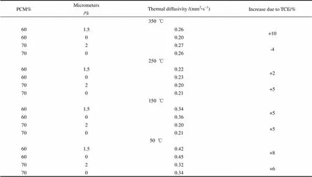
Table 2 Thermal Diffusivity across the operating temperature for varying amounts of PCM and micrometers
3 Conclusions
Salt based ceramic composite PCMs were prepared and characterised. Different carbon materials were added to enhance thermal conductivity of the PCM composites. The PCM composites were fabricated by mixing of the three materials, uni-axial compression and sintering. The microstructure, latent heat, thermal diffusivity and thermal stability were studied. The following conclusions could be obtained:
(1) The likelihood of PCM leakage during sintering increases with increasing PCM loading or increasing graphite content. PCM leakage was also found to be more likely to occur in composites containing high concentrations of spherical carbon nanoparticles.
(2) There is a clear change in the microstructures of the composite PCMs due to the addition of carbon materials.
(3) PCM composites containing micron sized carbon particles have a higher latent heat of fusion compared with these containing carbon nanoparticles.
(4) The addition of micron sized carbon particles increases the thermal diffusivity of the PCM composites by ~10% at a TCE content of 1.5% by mass, whereas the addition of spherical carbon nanoparticles and carbon nanotubes decrease the thermal diffusivity of the PCM composites. Such observation is attributed to the two related competing processes—The addition of carbon increases the thermal diffusivity on one hand but also increases the porosity which leads to a decrease in the thermal diffusivity.
[1] Energy Information Administration. International energy outlook 2016[R]. EIA, 2016.
[2] AHMED S F. Recent progress in solar thermal energy storage using nanoparticles[J]. Renewable and Sustainable Energy Reviews, 2017, 67: 450-460.
[3] MYERS P D, GOSWAMI D Y. Thermal energy storage using chloride salts and their eutectics[J]. Applied Thermal Engineering, 2016, 109: 889-900.
[4] Energy Gov, “Energy Storage,” 2016[EB/OL]. [2016-10-25]. http://energystorage.org/energy-storage/energy-storage- technologies.
[5] IBRAHIM H, ILINCA A, PERRON J. Energy storage systems—Characteristics and comparisons[J]. Renewable and Sustainable Energy Reviews, 2007, 12: 1221-1250.
[6] SHARMA A, TYAGI V, CHEN C, BUDDHI D. Review on thermal energy storage with phase change materials and applications[J]. Renewable and Sustainable Energy Reviews, 2009, 13: 318-345.
[7] ZALBA B, MARIN J, CABEZA L F, MEHLING H. Review on thermal energy storage with phase change: Materials, heat transfer analysis and applications[J]. Applied Thermal Engineering, 2003, 23: 251-283.
[8] DINCER I, ROSEN M A. Energetic, environmental and economic aspects of thermal energy storage systems for cooling capacity[J]. Applied Thermal Engineering, 2001, 21: 1105-1117.
[9] ALVA G L. Thermal energy storage materials and systems for solar energy applications[J]. Renewable and Sustainable Energy Reviews, 2017, 68: 693-706.
[10] GE Z, LI Y, LI D, et al. Thermal energy storage: Challenges and the role of particle technology[J]. Particuology, 2014, 15: 2-8.
[11] GOMEZ J. High-temperature phase change materials (PCM) candidates for thermal energy storage (TES) applications[M]. National Renewable Energy Laboratory, 2011.
[12] ANEKE M, WANG M. Energy storage technologies and real life applications—A state of the art review[J]. Applied Energy, 2016, 179: 350-377.
[13] JEGADHEESWARAN S, POHEKAR S D. Performance enhancement in latent heat thermal storage system: A review[J]. Renewable and Sustainable Energy Reviews, 2009, 13(9): 2225-2244.
[14] FAN L, KHODADADI J. Thermal conductivity enhancement of phase change materials for thermal energy storage[J]. Renewable and Sustainable Energy Reviews, 2011, 15(1): 24-46.
[15] LIDE D R. CRC handbook of chemistry and physics[M]. 90 Ed. Boca Raton, Florida: CRC Press, 2009.
10.12028/j.issn.2095-4239.2017.0079
TK 02
A
2095-4239(2017)04-688-08
2017-05-29; Revise date:2017-06-21.
Fundation: Global Energy Interconnetion Research Institute Europe GmbH (SGRI-DL-71-16-018), The National Natural Scierce Fund (21406243).
The first author and corresponding author: NAVARRO M E(1979—), female, research fellow, research in thermal energy storage, E-mail: h.navarro@bham.ac.uk.
