一种宽负载的LLC谐振变换器的优化控制方法
2017-07-06许晓婷
夏 熙, 许晓婷
(1.东南大学 国家专用集成电路及系统工程中心, 南京 210042;2.上海WPG智慧水务科技有限公司, 上海 200000)
一种宽负载的LLC谐振变换器的优化控制方法
夏 熙1, 许晓婷2
(1.东南大学 国家专用集成电路及系统工程中心, 南京 210042;2.上海WPG智慧水务科技有限公司, 上海 200000)
提出了一种优化的LLC谐振电路控制方法。该方法可使LLC电路运行在一个宽的负载条件下,同时能在负载切换时有一个好的闭环动态效果。提出的方法在稳态时采用并行双PID控制,由此解决了常规PID无法解决的负载宽度问题;在负载变化时采用基于状态轨迹法的优化控制来实现常规PID无法快速调节的问题。利用这2种控制方法的组合实现了在 400 V/24 V 150 W的半桥LLC电路上的仿真验证与实验样机验证。
LLC谐振变换器;优化状态;轨迹控制
1 Introduction
LLC resonant converter has been widely used in consumer or industrial fields and it is an excellent candidate for front-end DC/DC applications because of its high efficiency and hold-up capability [1].
However, compared with PWM converter, it is well known that it is difficult to analysis and control the LLC resonant converters because that the complex operation modes existing in the resonant tank. Also, the average modeling method isn’t a good method to predict the dynamic performance of the LLC because of the relationship between the natural frequency and the switching frequency. Thus, many methods and strategies have been proposed to build the model of the LLC and control the LLC. The extended describing function (EDF) [2-6] can provide a accurate small signal model of the resonant converters and the state-trajectory [7-9] can intuitively describe the resonant tank dynamic behavior.
The traditional control of LLC resonant converter is voltage mode control with only one-way linear compensation based on small-signal model, this means the load range of LLC is limited because of the limited bandwidth and the performance of load transients isn’t ideal because of the fast dynamic characteristics of the resonant tank. Many methods have been proposed to solve this problem, some like current mode control [10], average current mode control [11], bang-bang charge control [12], charge current control [13] and fuzzy control [14]. Current mode control and average current mode control are too complex to sense the resonant current of the resonant tank, also, these two methods are analog methods, so some non-linear control algorithm can’t be applied. Bang-Bang charge control is also a analog methods, this method proposes a good closed performance and a simple current detection circuit compared with current mode control, but this method can’t ensure the same duty circle for two switching tubes in primary side. Charge current control is a improved method for bang-bang charge current, but this method is lack of the experiment results. Fuzzy control is an advanced PID control, this method is very simple but the performance of the closed loop doesn’t significant improved.
This paper proposes an optimized control for LLC resonant converters which compare two paralleled digital control in steady state with the optimized trajectory control in load transients to insure a wider load range and an optimal load transients. The compared two paralleled digital PID control are designed to cover the wider load range. By forcing the state variables to track the desired trajectory, the optimized trajectory control can ensure the time required to reach the new steady state is minimal and overshoot is avoid at load transients compared with traditional PID control.
First, the operation principle of the proposed optimized control will be illustrated. Second, The design of the control in steady state and the optimized trajectory control in load transients will be introduced. Finally, the co-simulation of the proposed control with saber and matlab will be given and experiment results are demonstrated on a 150 W 200 kHz 400 V/24 V LLC converter.
2 Operation principle of the proposed optimized control
2.1Theproposedsystemstructuredrawing
Fig.1 shows the system structure drawing of the proposed control including the control parts, the control parts include two paralleled digital control to insure a good closed-loop performance in a wide load range.
2.2Theoperationprincipleoftheproposedcontrol
The flow chart of the proposed control is showed in Fig.2. At first, the system starts work and the output voltage and the load current can be sampled by the digital control, then the control system will judge the sampled load current, if the load current located in the area where the PID1module can regulate, the PID1 will work, otherwise, the PID2 module will work. At the load transients, the current optimized algorithm which based on the trajectory control will take over to give a ΔTthat compare with the period that gave by PID modules. At the steady states, the system only be controlled by PID modules, however, the combination with the PID modules control and the current optimized algorithm will work at the load transients.
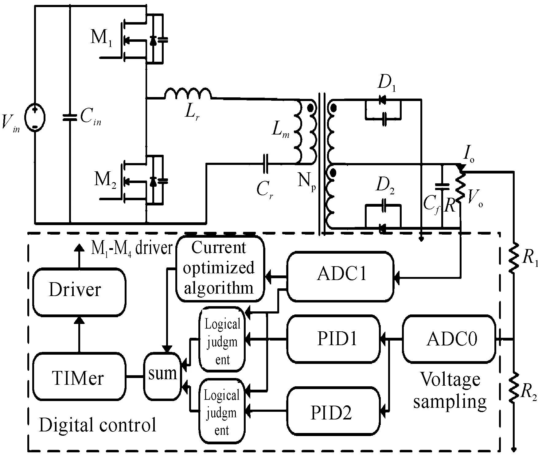
Fig.1 The system structure drawing of proposed control

Fig.2 The flow chart of the proposed control
3 The design of the proposed control
3.1ThedesignofthePIDmodules
Fig.3 shows the circuit of the resonant converter, Fig.4 shows the equivalent circuit of the LLC resonant converter. In the equivalent circuit,ir,im,Vcr,Vcoare static volume,VABis the system input andVois the system output.

Fig.3 LLC circuit Fig.4 LLC equivalent circuit
Based on the equivalent circuit, the equations of theVABcan be get

(1)
Basedontheextendeddescribingfunction,thenonlinearvolumecanbereplacedwithequationsas
vAB=f1(d,Vin)sinωst
nsgn(ip)vo=f2(ips,iRs,vo)sinωst+
f3(ipc,iRc,v0)cosωst
iR=f4(ips,ipc)
(2)
UtilizethestateequationsbasedontheEDF,thetransferfunctionofLLCconvertercanbeget,inthispaper,theexamplesas:vin=400 V,vo=24 V,Lm=470.87 μH,Cr=8.07 nH,Co=220 μF,fs=200 k,
rs=15 mΩ,rc=15 mΩ,RL=4 Ω. The transfer function can be expressed as:
F=
Based on the transfer function, the bode chart can be drawn and the compensation can be design to control the steady state.
3.2Thecurrentoptimizedalgorithmbasedontrajectorycontrol
The current optimized algorithm at the load transient is based on trajectory control and the trajectory control is proposed based on the graphical state-plane analysis.
Fig.5 shows the trajectories of the different loads(from light load to heavy load), every circle represents a steady state at a constant load, the heavier the load is, the larger the circle radius will be, when the load steps, the optimized trajectory control will be applied by changing the pulse widths of the driving signals to reduce the frequency to force the state variables to hit the new steady state. By sensing the current of the output and suppose the resonant current at the load step is constant, the relationship between the output current and the difference between the cycles(t1~t2)can be estimated. Fig.6 shows the resonant voltage and resonant current in resonant tank and exciting current in time-domain, supposing the current is constant when exciting current reach the resonant current, the value of this current is (3),iris the resonant current,imis the exciting current,nis the turn ratio,v0is the output voltage andLmis the resonant inductance and during the time(t1~t2) at load step, the resonant capacitor will be charged and the resonant current will be increased to meet the load current requirement to realize the optimized dynamic regulation, the resonant voltage att1can be estimated is(4) and resonant voltage att2can be estimated is(5),Vcris the resonant voltage andVinis the input voltage. At last the relationship between the load current and difference between the cycles can be estimated is (6), though the geometric relationships in the state trajectory figure of the resonant tank, the geometric relationship is shown in Fig.7.
(3)

(4)

(5)

(6)

Fig.5 The trajectories of the different loads
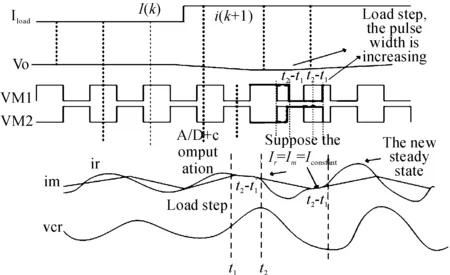
Fig.6 The strategy of the sampling


4 The simulation and experimental results
The co-simulation of the proposed control with saber and matlab is implemented and the simulation is verified on a 400 V/24 V LLC converter. The comparison of the simulation results of the load step-down(8 A-2 A) between the traditional voltage control mode and combination control are shown in Fig.8 and Fig.9. The results of the simulation proved that the load extended from 1.67~13 A to 0.5~13 A. The experimental results of the load step-down(8 A-2 A) on a 400 V/12 V is shown in Fig.10.

Fig.9 The proposed control

Fig.10 Experimental result(8 A-2 A)
5 Discussion and conclusion
In this paper, the optimized digital control of LLC converter is investigated to extend the load range and improve the performance of the load transients. The co-simulation and the experiment verify the results of the co-simulation. The most advantage of this digital control is that more advanced algorithm can be applied and the more accurate control can be carried out. But there are some problems in this control, when the resonant frequency increases, this control requires high performance controller and it is difficult to catch the point of the load step and to get more accuratet2~t1, the more accurate calculation should be studied.
[1] YANG B.Topology investigation for front end DC-DC power conversion for distributed power system[D].Virginia,USA:Dissertation in Virginia Tech,2003.
[2] KING R J,STUART T A.Small-signal model of the series resonant converter,IEEE Trans[J].Electron Syst,1985,21(3):1-319.
[3] YANG B,LEE F C.Small-signal analysis for LLC resonant converter[C]//CPES Seminar.2003:144-149.
[4] YANG E X,LEE F C,JOVANOVIC M M.Small-signal modeling of LCC resonant converter[C]//Proc.IEEE-PESC’92.1992: 167-178.
[5] TIAN Shuilin,LEE F C,LI Qiang.Equivalent circuit modeling of LLC resonant converter,Power Electronics[J].IEEE Transactions,2016,31(5):1251-1259.
[6] CHENG B,MUSAVI F,DUNFORD W.Noval small signal modeling and control of an LLC resonant converter[C]//Proc.IEEE APEC.2014:2828-2834.
[7] LEE C Q,SIRI K.Analysis and design of series resonant converter by state plane diagram[J].IEEE Trans.on Aeros and Electron.Syst,1986,22( 6):757-763.
[8] KIM M,KIM J.Modeling and optimal trajectory control of the series resonant converter pulse-width modulated or current-controlled for low switching loss[C]//Proc.IEEE-APEC’1993.1993:752-758.
[9] FENG W,LEE F C,MATTAVELL P.Implified optimal trajectory control(SOTC) for LLC resonant converters.Power Electronics[J].IEEE Transactions on,2013,28(5): 2415-2416.
[10]JANG J,JOUNG M,CHOI S,et al.Current mode control for LLC series resonant dc-to-dc converters[C]//Proc.Int.Power ELectron.Conf and Expo.(APEC’11).2011:21-17.
[11]JANG J,KUMAR P S,KIM D,et al.Average current-mode control for LLC series resonant dc-to-dc converters[C]//proc.Int.Power Electron.And Motion Control Conf.(IPEMC’12).2012:923-930.
[12]HU Z,WANG L,LIU Y F,et al.Bang-Bang charge control for LLC resonant converters[C]//Proc.Energy Convers,Congr,and Expo.(ECCE’13).2013.
[13]HANGSEOK C.Charge current control for LLC resonant converter[Z].[S.l.]:IEEE,2015.
[14]CONCETTINA B,CARLO C.Hamed Latafat and kaveh Razi.Digital control of a half-bridge LLC resonant converter[C]//EPE-PEMC 2012 ECCE Europe.Novi Sad,Serbia:[s.n.],2012.
(责任编辑 杨黎丽)
An Optimized Control for LLC Resonant Converter With Wide Load Range
XIA Xi1, XU Xiao-ting2
(1.National ASIC System Engineering Research Center, Southeast University, Nanjing 210042,China; 2.WPG(Shanghai) Smart Water Technologies,Shanghai 200000, China)
This paper presents an optimized control which makes LLC resonant converters operate with a wider load range and provides good closed-loop performance. The proposed control employs two paralleled digital compensations to guarantee the good closed-loop performance in a wide load range during the steady state, and an optimized trajectory control will take over to change the gate-driving signals immediately at the load transients. Finally, the proposed control has been implemented and tested on a 150 W 400 V/24 V LLC resonant converter and the result validates the proposed method.
LLC; optimized control; optimized trajectory analysis
2017-03-06
东南大学国家工程实验室与苏州博创公司合作项目
夏熙(1992—),男,硕士研究生,主要从事功率电子、DCDC变换器研究,E-mail:m1520516941_1@163.com。
夏熙, 许晓婷.一种宽负载的LLC谐振变换器的优化控制方法[J].重庆理工大学学报(自然科学),2017(6):166-170.
format:XIA Xi, XU Xiao-ting.An Optimized Control for LLC Resonant Converter With Wide Load Range[J].Journal of Chongqing University of Technology(Natural Science),2017(6):166-170.
10.3969/j.issn.1674-8425(z).2017.06.025
TM46
A
1674-8425(2017)06-0166-05
